DUAL BAND GNSS ANTENNA PHASE CENTER CHARACTERIZATION FOR AUTOMOTIVE APPLICATIONS
Micro-relief and polygon geometry
1. Micro-relief and geometry of ice-wedge polygons in Adventdalen (Svalbard, Norway)
M. Lousada(1), M. Jorge(2), J. Saraiva(1,3), P. Pina(1), and G. Vieira(2)
(1)Instituto Superior Técnico, Lisboa, Portugal, (2)CEG / IGOT, Lisboa, Portugal, (3)UNIS, Longyearbyen, Norway
Research developed within the project ANAPOLIS (PTDC/CTE-SPA/099041/2008),funded by FCT (Portugal)
INTRODUCTION
Ice-wedge polygons mostly occur in flat areas, but they have also been found in slopes with gradients as high as 25°; in these cases, they are commonly elongated in the
downward direction. However, even seemingly flat terrains exhibit small-scale topography; in this work, we conduct a detailed analysis of polygon shape in relation with micro-
relief in a polygonal network in the Adventdalen valley, in Svalbard (Norway). In the frame of the ANAPOLIS (Analysis of Polygonal Terrains on Mars based on Earth Analogues)
project, we have made two field campaigns to fully characterize an extensive polygonal network (with an area circa 40,000 m2) in this periglacial area in the Arctic (78° N).
METHODS RESULTS Adventdalen Topographic map and ESRI Base Maps
A FIELD SURVEYS B DTM DERIVED FROM THE FIELD SURVEYS 85 % OF THE 163 POLYGONS HAVE A HIGHER
A DTM was generated by interpolation from the 8166 (x,y,z) points gathered with the GPS in the VERTICAL DISTANCE ALONG THE MAJOR AXIS
course of the two campaigns. The delineation of polygons was achieved through analysis of aerial
images combined with field information.
Results point to an existing relation between the orientation of
Two field campaigns were conducted, in 2010 the major axis of polygons and that of the slope of the terrain; in
and 2011. The precise location of points in the other words, the distribution of major axis orientations follows
field was determined through the use of a closely the distribution of slope gradients.
GNSS-RTK geodetic system. 2
1
In the central area of the
network, the contours of 121
polygons were also surveyed.
Coordinates were collected at The combination of all that information led to the construction of a detailed model of the micro-
the centre of the troughs topography in the central area of the network, covering 163 polygons. Thus, we can now
separating adjacent polygons. evaluate the relation between geometry and micro-relief fluctuations for this set of low-centred
polygons.
C DETERMINING VERTICAL DISTANCES ALONG THE AXIS 1) Box Plot 3
Shows higher Vertical Distance values for major axis.
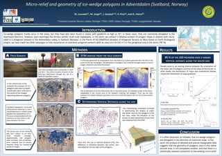
A gridded topographic survey was
conducted by collecting x, y and z The methodology employed consisted 2) Quantile-Quantile Plot
coordinates every 5 meters along in determining the lengths of major Shows a marked difference between VDs for the two
and minor axes for the polygons in the axes, again illustrating the fact that major axes
parallel lines separated by 10 m. correspond to higher VDs
This was complemented with the test area, while the elevation of the
collection of more points in the terrain on both extremities of each axis 3) Density Plot
areas between the lines. was obtained from the DTM. Density plot for Major and minor axis vertical
distances density distributions. Several minor axis
have less then 20 cm of vertical distance.
The central part of the network
was later subject to an even CONCLUSION
more detailed coverage.
Approximately 150 polygons It is often observed, on hillsides, that ice-wedge polygons
were surveyed, and coordinates are elongated in the direction of maximum slope. In this
were collected also at several From this, the rise or Vertical Distance (VD), the work, the analysis of detailed and precise topographic data
locations along the transversal difference in elevation between two points, was
profile of troughs.
suggests that the geometry of polygons, even in this rather
calculated for the two axes of the polygons.
smooth area, is not completely random, and that there is a
statistically relevant connection to the existing micro-relief .