1. Star Camera Baffles for BLAST-TNG
University of Pennsylvania
Mark Giovinazzi, Dr. Mark Devlin
References
Introduction
Materials and Methods
Results Conclusion
Future Work
The BLAST-TNG experiment is chosen to fly in December, the eve of the
Antarctic summer; during this time of year in the South Pole, constant
sunlight is unavoidable. While BLAST-TNG benefits from such conditions
since it is powered by solar panels, the abundance of sunlight concurrently
puts the efficiency of its star cameras at extreme risk. Although the cameras
need to absorb photons from stars in front of them, the sun's immense power
would otherwise blind the cameras with unnecessary light; the star camera
baffles were designed to block all such light.
In order to create an effective design for the star camera baffles, we had to
work under several constraints. First, we had to account for the 1.6º opening
angle of the star cameras. To supply enough room for error during assembly,
our model’s opening angle was set to be 1.8º, meaning that all incoming light
with an angle of 1.8º or less will be allowed to reach the lens. The second
constraint was that the length of the star camera baffles had to exceed that of
the sunshields, which is about 69 inches; to again provide some room for
error, the total length of our design was made to be an even 72 inches. The
final model chosen involves two cylindrical trusses attached to one each
other, the first of which bolts onto the star camera and has a radius of 8.75
inches to account for the bolt pattern of the star camera and the second of
which is larger, stepping up in diameter to 11 inches to account for the ever-
increasing inside diameter due to the opening angle of the star camera baffle.
Carbon fiber tubes were selected to build our trusses in order to provide a
good blend between lightweight and strong. To support the two cylindrical
trusses and hold the tubes in place, aluminum was chosen,considering that it
is relatively cheap, light, and strong. We used the metal to make three rings,
one of which would bolt onto the star camera, while the other connected the
two different sized trusses together, and the last constrained the carbon fiber
tubes at the top of the star camera baffle. To help block light from reaching
the lens, 1/32 inch carbon fiber disks were placed in the star camera baffle in
such ways that all unnecessary light could be blocked. We then wrapped the
sides of our star camera baffle to prevent light from entering anywhere but
the opening. For this, 0.002 inch thick matte black aluminum wrap with an
absorptive rating of 95% was picked, such that light bouncing on the inside
could be easily absorbed. We decided that if a photon were to bounce more
than three times off of this foil, we would no longer care about blocking it, as
it will have a 99.9875% chance of having been absorbed. Finally, the trusses
were spray painted a flat black to absorb, while the outside would be coated
in a glossy white to reflect, such that the star camera baffle does not overheat.
Having the general structural design in place, the only task remaining was to
determine the optimal positioning of the carbon fiber baffles such that all
unwanted light is blocked. With the three bounce limit in mind, we needed to
position a series of disks inside the star camera baffle to do the blocking of
all light that bounces between one and three times and would otherwise reach
the star camera lens. Note that if the photon bounces 0 times, it is coming
from the front and is therefore light that we care to observe. A unique code
was written using Python to determine exact locations of these carbon fiber
baffles, the result of which produced their locations in such fashion as to
absorb 100% of light our circumstances deemed undesirable.
Standing at 72 inches and weighing in at 5.5 pounds, the new star camera
baffles designed for the BLAST-TNG experiment are 40% longer and
40% lighter than those used for the previous experiment, BLAST-Pol. The
additional length was a necessary improvement because of the updated
design of the experiment, since the new sunshields will be bigger and
therefore reflect more light; they had to be long enough to exceed this.
However, the fact they they are so much lighter allows for the extra
length, and in addition induces less hull on the experiment.
Not sure if there are any general BLAST references I should include here.
The current launch date for BLAST-TNG is in December of 2017. This will
make for the official testing of the star camera baffles, and the success of
the experiment is certainly dependent on them. While we will know much
more about the benefits and reproducibility of our star camera baffles after
the experiment has flown, the hope is that this new model for the star
camera baffles will continue to be used for the inevitable future flights
from the BLAST group, and that this design will be adapted and utilized by
other such experiments.
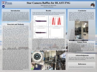
Through experimentation with the aforementioned code, seven baffles were chosen to be placed
at unique spots such that 100% of the unwanted light would be blocked from reaching the star
camera. To demonstrate the accuracy of this, the following plots were generated.
Acknowledgments
This research would not have been possible without the tremendous
assistance of Dr. Mark Devlin, Jeff Klein, Elio Angilè, Federico Nati,
Nicholas Galitzki, Nathan Lourie, and Brad Dober.
The top two plots demonstrate the effectiveness of the star camera baffles without any individual
baffles placed inside of the structure, while the lower two plots demonstrate the effectiveness of
the star camera baffles with the experimentally chosen locations of the seven individual baffles
(note that the center aluminum ring also acts as a baffle). The star camera lens is indicated in the
top left plot via dashed lines, so the fact that no colored beams make it into that region is ideal.
On the bottom right we see an empty plot, meaning that there are no combinations of initial angle
and height from the center entering the star camera baffle which will allow any indices of light to
reach the star camera; again, this is ideal. Overall, these plots shore up any doubt that undesired
photons will be seen by our star cameras during flight. Below are images of the star camera
baffle at various stages of its construction, putting on display all of its various components.
THENEXTGENERATI
ON
BALLOON-BORNE
LARGE
APERTURESUBMILLIMETRET
ELESCOPE-