
Recommended
More Related Content
Similar to X-RAY HISTORY
Similar to X-RAY HISTORY (20)
Recently uploaded
Recently uploaded (20)
X-RAY HISTORY
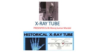
- 1. X-RAY TUBE PRESENTER:Sr.Rt.Manoj kumar Mandal
- 2. CONTENTS INTRODUCTION HISTORY OF XRAY TUBE HISTORY OF DEVELOPMRNT OF XRAY TUBE PRINCIPLE X-RAY TUBE COMPONENTS FEATURES OF TUBE METHOD OF HEAT DISSIPATION TUBE RATING TUBE FAILURE CAUSE CARE OF TUBE
- 3. INTRODUCTION An x-ray tube functions as a specific energy converter, receiving electrical energy and converting it into two other forms of energy: x- radiation (1%) and heat (99%). Heat is considered the undesirable product of this conversion process; therefore x-radiation is created by taking the energy from the electrons and converting it into photons. This very specific energy conversion takes place in the x-ray tube.
- 4. HISTORY OF X-RAY TUBE:BEFORE AND AFTER "After Roentgen" - Tubes Designed to Produce X-Rays The small paper label on the evacuation arm reads "Pat. applied for. Aetna Electric Co. Manufacturers." The tube is of a very early design, probably 1890s. Given the concave cathode and sloped target, it was specifically designed to produce X-rays. The bulb (on the right end in the photo) was probably intended to counteract the variations in output that were characteristic of the early cold cathode tubes.Size: Approximately 12" long with 2 1/2" bulb diameter
- 5. Air-Cooled X-Ray Tube (1915-1925) • The aluminum cathode, a little hard to make out, is located at the point where the glass arm enclosing it is attached to the right side of the spherical bulb (as seen in the photo). • Air-Cooled X-Ray Tube (1915-1925) • The anode is the pointed aluminum rod inside the glass arm attached to the lower left portion of the bulb. And now, the information you have been waiting for, how this tube’s air cooling system works. The anticathode is supported by a hollow glass tube the screen-covered open end of which is shown to the right. This design permitted a passive circulation of air that would cool the target during prolonged periods of heavy use. A forced circulation of air would be more effective, but this particular tube was not designed to accommodate it.Size: Approximately 20" long with 8" bulb diameter.
- 6. Cold Cathode X-Ray Tube (early to mid 1900s) • The cathode, as always, is positioned on the periphery of the spherical portion of the tube (in the photo, it is on the lower left side of the bulb, but it is not easily recognizable ). The anode, a simple aluminum rod, is on the long axis of the tube inside the glass arm attached to the upper right side of the bulb (as seen in the photo). The anticathode enters the tube at a 45 degree angle (from the lower right in the photo) with the circular target located in the middle of the bulb. • Obviously, the tube lacks a regulator to control the gas pressure—a serious disadvantage if the intent was to use the tube for extended periods. • As is true for most tubes of this design, the manufacturer is unknown. There are no markings of any type on the tube's glass or metal components. However, from its general appearance, I would guess that it was produced between 1925 and 1950 or so, and that it was intended for classroom demonstrations. • The lack of corrosion on the contacts, the absence of damage to the target and the lack of any coloring of the glass indicates that it saw little to no use.
- 7. Crookes Tube (ca. late 1800s) • This is the classic version of what is often known as a Crookes tube. Developed by William Crookes to investigate electrical discharges in gas. Although it is not certain what type of tube Rontgen was using when he discovered X-rays, this is the type of tube most commonly assumed to be involved. These tubes had two major shortcomings in terms of their ability to produce X-rays. First, because the X-rays originated over a rather large area, the resulting X-ray images lacked sharpness. Second, the low intensity X-ray output required long exposures and these tubes could not hold up to the workload. • Perhaps the first major advance in X-ray tube design was the incorporation of a metal target, something that resulted in greater X-ray intensities than possible with a glass target. Nevertheless, the use of glass as a target had some advantages and the method was not completely abandoned. For example, see the collection's cold cathode therapy tube. • Size: 11" long, 4" maximum bulb diameter
- 8. Jackson X-Ray Tube (ca. 1896) • Following Rontgen's discovery of X-rays in late 1895, the first significant development in the design of X-ray tubes was the use of a concave cathode that focused the electrons (cathode rays) on the target. William Crookes had constructed such a tube many years earlier, but not, of course, to increase the production of X- rays. Various workers (e.g., Sidney Rowland and Herbert Schallenberger) made X-ray tubes with concave cathodes in early 1896, but rightly or wrongly, professor Herbert Jackson of Kings College in London is usually credited as being the first to do so. • As seen in this example, the Jackson tube was usually oriented so that the cupped cathode faced down while the upwardly facing target (typically platinum) was mounted at 45 degrees to the tube axis. • It is not visible in the photo, but the glass stem supporting the anode is cracked, probably because of a drop during shipping. As a result, the cathode and anode don't line up correctly. • Size: ca. 11" high (including stand) and 3" diameter
- 9. Pregnant Jackson X-Ray Tube (ca. 1896-1900) • This is a somewhat unusual modification of a Jackson tube. What makes it unusual is the fact that the bulb is offset from the long axis of the tube. It almost looks as if the tube were pregnant. • Perhaps the idea was to increase the distance between the target and that portion of the bulb wall towards which the X-rays were directed. This would minimize heating of the glass, at least to some extent. The small tube illustrated in the advertisement at the bottom of the page shows a somewhat similar design. • The cup-shaped aluminum cathode is located in the glass arm just above (as seen in the photo) the point where the arm connects to the top of the spherical bulb. The anode, which serves at the target, is oriented at 45 degrees to the tube axis. It is almost certainly made of platinum. • Unfortunately there are no visible markings that might assist identify the manufacturer. • Size: ca. 11" long and 2.5" diameter.
- 10. CONT. Pressler Cold Cathode X-Ray Tubes (ca. 1910-1950) Early Kesselring Cold Cathode Tube (1900-1910) Gundelach "Moment" X-Ray Tube (1912-1920) Piffard Safety X-Ray Tube with Heavy Anode (ca. 1910) Piffard Safety X-Ray Tube with Light Anode (ca. 1910)
- 11. Water-cooled X-Ray Tube of Unknown Manufacture (ca. 1916-1920) This example of a water-cooled X-ray tube (the only one in the collection) dates from 1916 to 1920 simply because the metal collar around the cathode is stamped 1916. While there is nothing on the tube that would indicate the manufacturer, it is similar in appearance to the drawing of a Macalaster & Wiggin tube in the 1919 text “Radiography and Radio-therapy” by Robert KnoxThis particular tube belonged to M. J. Gross who worked with Dr. Coolidge at General Electric in Schenectady, N.Y. Gross later became vice president of the GE X-ray Company. During the 1930s and 1940s, Gross and Zed Attlee formed the core of Coolidge's research and design team. Size: Approximately 7" diameter bulb, 23" long.
- 12. "Before Roentgen" - Tubes not Designed to Produce X-RAY The Radiometer was invented in the 1870s by William Crookes during his investigations as to why light was affecting the measurements he was making with a very sensitive balance. His work with the Radiometer lead him to the development of a variety of gas discharge tubes collectively referred to as Crookes tubes. The design of the Radiometer is the obvious inspiration for his "Railway" tube. The examples on display, no longer working, are difficult to date but were probably manufactured in the early 1900s. The figure to the right is from the 1914 catalog of the Otto Pressler company.
- 13. Crookes Railway Tube (ca. 1910-1950):This type of gas discharge tube (aka paddle wheel tube) was invented in the 1880s by William Crookes as part of his investigations into the nature of cathode rays (electrons).
- 14. Crookes Tube With Three Anodes: When the high voltage is applied, the cathode rays leaving the cupped cathode form three beams—one beam going to each anode as indicated in the drawing above left. The beams are visible due to the fluorescence of the gas molecules caused by the electrons traveling through the tube. The age of this tube is uncertain, possibly late 1800s but more likely early 1900s. Size: Approximately 14" high (including base) with 5 1/2" bulb diameter The above image is from the Ott Pressler catalog of 1914
- 15. Geissler Tubes (early 1900s) • The two examples shown here are relatively small and simple versions of the device invented by Heinrich Geissler in the mid-1850s. Known as Geissler tubes, these are the forerunners of modern neon and fluorescent tubes. • Each partially evacuated tube has an electrode at each end. When a high voltage is applied across these electrodes, the tube emits light of a color that depends on the type of gas in the tube. • They were originally used for the spectroscopic analysis of gases, but they also served as curiosities for entertainment purposes. Although they played no role in the discovery of X-rays, some of the techniques developed for their production were used to construct X-ray tubes. • The yellow sections of these tubes are made of uranium glass. • Size: Approximately 9" long with a one-bulb diameter The following figure from the 1914 catalog of the Otto Pressler company .
- 16. Heating Effects Tube (early 1900s) • The "heating effects tube" was created in the late 1800s by William Crookes to demonstrate the amount of energy carried by the cathode rays (electrons) that stream from the cathode to the anode. The magnitude of this energy was indicated by the fact that the platinum foil in the center of the tube glowed red when a high voltage was applied. Size: Approximately 13" high (including base) with 4" bulb diameter The drawing above was taken from the 1914 catalog of the Otto Pressler company.
- 17. Maltese Cross Crookes Tube (ca. 1910-1940) • The Maltese Cross tube was invented in the 1880s by William Crookes during his investigations unto the nature of cathode rays (electrons). • The tube's distinctive feature is the Maltese Cross that could be laid flat or stood up. • It has been speculated that Crookes used a Maltese Cross because the pronunciation of his name is not that different from the pronunciation of the Latin word for cross: crux. Shadow image of cross on end of tube The figure is from the 1914 Otto Pressler catalog.
- 18. HISTORY OF DEVELOPMENT OF X-RAY TUBE
- 19. PRINCIPLE OF X-RAY TUBE
- 21. CONT.
- 22. LIMITATIONS
- 23. HOT CATHODE TUBE
- 24. CONT.
- 25. OLD VS NEW
- 26. FEATURES OF AN X-RAY TUBE(MODERN)
- 27. COMPONENTS
- 29. HOUSING
- 30. COMPONENT OF TUBE UNIT:
- 31. COMPONENT GLASS ENCLOSURE VACCUM HOUSING CATHODE FOCUSING CUP FILAMENT ANODE SIDE TARGET LINE FOCUS PRINCIPLE HEEL EFFECT
- 33. CONNECTING WIRES
- 34. SPACE CHARGE
- 35. KV AND SPACE CHARGE
- 36. TYPES OF X-RAY TUBE
- 41. METHOD OF HEAT DISSIPATION
- 42. ROTATING ANODE X-RAY TUBE
- 43. MAIN FEATUREA OF ROTATING ANODE
- 44. CONT.
- 45. HEAT RATING
- 46. HOW TO MAXIMIZE X-RAY TUBE LIFE
- 48. CONT.
- 49. CONT.
- 50. ADVANTAGE
- 51. TYPES OF X-RAY TUBE
- 52. MAMMOGRAPGY TUBE
- 54. CONT.
- 55. CONT.
- 56. TRANSMISSION TYPE OF TUBE
- 57. DEVELOPMENT
- 58. CT-TUBE
- 59. TUBE RATING
- 61. CONT.
- 63. AREA OF TUBE FAILURE
- 64. CAUSE OF TUBE FAILURE
- 65. CARE OF X-RAY TUBE
- 67. REFRENCES
- 68. ?
- 69. THANK YOU