1. Introduction and Overview
This laboratory experiment is an exercise of assembly code design and debugging using
CodeWarrior IDE (Integrated Development Environment). Using basic coding
commands in Assembly I am going to drive the 7 segment display on the Dragon12-PlusUSB development board. The 7 Segment display will present my birth year and name
separately, since there are only four 7 segments displays.
Equipment and Parts
This lab uses the Dragon12-Plus-USB development board. CodeWarrior IDE is fully
capable of talking to the Dragon board via USB using the serial monitor. In previous labs
we used full chip simulation, this is changed by clicking on the serial monitor option
during the setup. The Freescale HCS12D Family Microcontroller was specified in the
software, specifically MC9S12DG256B.
Theory
I am going to have to start the code by telling my stack pointer where to start. I also want
to define my output and input ports. Previously when I defined my ports I would do
something like “a : OUTPUT”. This is of course AHDL, in assembly I define my ports
by either storing all 1’s or all 0’s in that port. I am going to make DDRB & DDRP
output ports, and therefore will store all 1’s or #$FF to the ports.
I will then define my variables such as R1, R2, and R3. Next I will compose my loop
code. I define my ports differently when writing data to them, such as turning on and off
the LEDs. When writing data to port B, for example, instead of calling it DDRB as I did
when defining my output, I call it PORTB. Refer to ‘derivative.inc’ source file for
variable names.
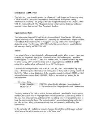
Direction Data
DDRB PORTB
DDRP PTP
PORTB is where I tell it what data I want displayed
PTP is used to tell the Dragon Board which 7 SEG to use
The delay portion of the code is needed, because without it I wouldn’t be able to see the
numbers, the code would be looping too fast for our eyes to see. All the delay portion of
the code does is take up time, and in assembly we take up time by writing instructions to
keep the microcontroller busy. The instructions don’t accomplish anything useful, they
just take up time. Many instructions take up time, such as storing and loading data
continuously.
In this particular lab I had almost no delay, because I wanted the code to cycle so fast it
would appear that all the numbers are on at the “same time”.
2. Design Calculations
Binary to Hex conversion
a
00110111
8 4 2 1 8 4 2 1
b
f
a
a
g
$
a
e
3
7
= $37
c
dp
a
a
d
a
a
#
dp
g
f
e
d
c
b
a
hex
1
0
0
0
0
0
1
1
0
$06
9
1
1
1
0
0
1
1
1
$E7
8
1
1
1
1
1
1
1
1
$FF
8
0
1
1
1
1
1
1
1
$7F
#
dp
g
f
e
d
c
b
a
hex
n
0
0
1
1
0
1
1
1
$37
I
0
0
0
0
0
1
1
0
$06
K
0
1
1
1
0
1
1
0
$76
E
0
1
1
1
1
0
0
1
$79
3. Schematic Diagram of The Circuits
Displaying my birthday on the 7 segment display
4. Displaying my name, or one similar to it on the 7 segment display
Notice I had to speed up the delay time so that there was almost no delay. This was
needed to display all the 7 segments at the “same time”.
5. Results
(click→debug)
It is clearly visible that the left picture displays 1988 and the right displays nIKE, of
course I included the dots to show I am capable of using them. If our eyes could see what
the code was actually presenting it would show:
8 is displayed then turned off
8 is displayed then turned off
9 is displayed then turned off
1 is displayed then turned off
repeat
Connecting the USB can be confusing. Once the USB has been connected I need to
check what port it is on.
Control Panel→System→Device Manager→ports (COM)
After finding out what com port is being used I then tell CodeWarrior what com port to
use.
Problems Encountered
This lab was particularly confusing, because it used 2 output ports. I had a hard time
wrapping my head around which port does what. I now understand and clearly explained
it in the theory section. This is because I am used to programming using Arduino, which
I would define the pins as an output in the beginning, but I can also write data to that
same pin (ie. Pin 1).
I also wanted to actually display all four 7 segments at the same time. I am not able to do
this, because I keep rewriting to PTP, which erases the data from the last instruction. In
order to accomplish turning all the 7 segment displays at the same time each display
would need its own port.
6. Conclusion
I have used some basic assembly commands to utilize the 7 segment displays. I only
used the code needed to avoid any unnecessary confusion. I have also displayed my
capability to debug my code and display the proper output via USB serial monitor. Using
the code framework provided by CodeWarrior and the information in Huang’s book I
was able to successfully complete the lab.