
Recommended
More Related Content
What's hot
What's hot (19)
Similar to #3 boss buffer od under size final
Similar to #3 boss buffer od under size final (20)
Recently uploaded
Recently uploaded (20)
#3 boss buffer od under size final
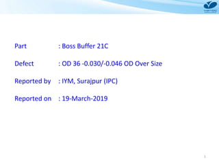
- 1. 1 Part : Boss Buffer 21C Defect : OD 36 -0.030/-0.046 OD Over Size Reported by : IYM, Surajpur (IPC) Reported on : 19-March-2019
- 2. ) March-2019 - Critical Quality Problem Model : 03F Title : OD 36 -0.03/-0.046) O/S Boss buffer (21C- E1496-20) Countermeasure <Found> Responsibility : M/s. Varroc Engg. Market Production Launching T.P. User Approved by S.ASAWA Checked by S. Patil Prepared by Harshal Occurrence: Out Flow: 1 # Training given to inspector about OD Inspection through SOP Imp. Date : 19-March-2019 # 100% inspection in 4-Jet Gauge. # A separate metal cage box with lock and key designed for inspectors to reject the part accordingly as per the job defect. # Packing Area table shifted exactly to the next of output. # MT4 180mm center replaced with MT4 140 mm length center. # Stopper with locking arrangement provided to restrict wrong length MT4 center installation. # Identification mark provided on MT4 center and linked with tool list and setup approval report. # Center MT4 with length 140 mm defined in set up change SOP. To avoid use of wrong length center 2 Out Line Of Problem CAUSEProcess Flow: 1st Find (Initial Analysis): 1 Occurrence: Out Flow:2 NG Parts laying at VEPL analyzed for physical phenomena Visual :No dent, damages observed on OD. Dimensional : High Ovality Observed on NG Parts Report Attached Why1 OD oversize by 0.03mm Why2 Non-Uniform grinding of the job. Why3 Grinding wheel dressing not happened properly. Why4 Dressing insert worn out. Not giving proper life. Why1 Inspection Error Why2 Judgemental error by operator. Conclusion :- Judgemental error by operator Problem Phenomenon: OD over size by 0.03mm Standard- ø36.0 (- 0.030/-0.046)mm Actual - Max ø 35.970(+0.05mm) - O/Size (19-Mar-19) C&E Analysis 2
- 3. 3 Initial Analysis Sr. No. Outer Diameter Concentricity Parallelism OD Ø36 (-0.030, -0.047) OD Taper OD Ovality 0.020 Max 0.040 Max Min. Max 0.005 Max 0.005 Max 1 -0.063 -0.052 0.003 0.011 0.016 0.027 2 -0.047 -0.037 0.003 0.01 0.018 0.029 3 -0.072 -0.065 0.002 0.007 0.015 0.024 4 -0.068 -0.061 0.004 0.007 0.018 0.02 5 -0.072 -0.063 0.003 0.009 0.018 0.03 6 -0.03 -0.022 0.002 0.008 0.016 0.026 7 -0.039 -0.028 0.003 0.011 0.019 0.031 8 -0.031 -0.02 0.001 0.008 0.015 0.032 9 -0.032 -0.024 0.003 0.008 0.013 0.028 10 -0.031 -0.021 0.004 0.01 0.015 0.02 Conclusion NG OK NG OK OK
- 4. 4 Co-Relation with Centre length - Before Dressing Frequency :- After 25 cycles (100 nos. Parts) Srl No Tail Stock Centre Length 180 mm Ovality (Spec :- 0.005) Concentricity (Spec:- 0.020) OD 36-0.030/-0.046 A B C D A B C D A B C D 1 0.004 0.003 0.004 0.003 0.009 0.012 0.014 0.007 35.962 35.964 35.964 35.958 2 0.003 0.004 0.003 0.009 0.011 0.010 0.015 0.019 35.961 35.962 35.962 35.972 3 0.005 0.004 0.004 0.002 0.012 0.011 0.012 0.014 35.964 35.960 35.960 35.964 4 0.005 0.003 0.003 0.004 0.011 0.012 0.016 0.006 35.962 35.960 35.961 35.962 5 0.004 0.004 0.003 0.002 0.013 0.013 0.014 0.009 35.959 35.964 35.962 35.962 6 0.004 0.003 0.003 0.008 0.012 0.012 0.016 0.019 35.959 35.962 35.962 35.973 7 0.003 0.004 0.004 0.003 0.015 0.011 0.014 0.012 35.960 35.960 35.962 35.961 8 0.003 0.004 0.003 0.008 0.009 0.012 0.016 0.015 35.962 35.965 35.961 35.952 9 0.004 0.003 0.004 0.005 0.012 0.013 0.013 0.007 35.961 35.964 35.964 35.962 10 0.004 0.004 0.003 0.004 0.013 0.012 0.014 0.009 35.962 35.962 35.963 35.962 11 0.003 0.004 0.004 0.006 0.012 0.011 0.015 0.015 35.964 35.959 35.962 35.972 12 0.003 0.003 0.004 0.003 0.011 0.012 0.016 0.007 35.968 35.959 35.961 35.961 13 0.003 0.004 0.003 0.004 0.012 0.012 0.017 0.012 35.962 35.960 35.964 35.964 14 0.004 0.004 0.004 0.003 0.014 0.014 0.018 0.009 35.961 35.962 35.961 35.963 15 0.004 0.003 0.003 0.005 0.016 0.015 0.014 0.015 35.962 35.961 35.962 35.962 16 0.004 0.004 0.004 0.005 0.012 0.013 0.013 0.010 35.962 35.962 35.958 35.960 17 0.003 0.003 0.003 0.007 0.012 0.015 0.012 0.016 35.960 35.964 35.962 35.953 18 0.003 0.004 0.003 0.007 0.010 0.012 0.014 0.015 35.960 35.965 35.964 35.952 19 0.004 0.005 0.003 0.004 0.009 0.013 0.016 0.006 35.961 35.961 35.962 35.962 20 0.003 0.004 0.003 0.006 0.010 0.015 0.014 0.014 35.962 35.959 35.967 35.972 21 0.003 0.003 0.003 0.004 0.012 0.012 0.013 0.018 35.964 35.959 35.965 35.965 22 0.004 0.004 0.004 0.003 0.013 0.012 0.014 0.019 35.965 35.958 35.966 35.964 23 0.003 0.004 0.004 0.004 0.013 0.013 0.015 0.016 35.962 35.959 35.962 35.962 24 0.003 0.003 0.003 0.004 0.014 0.014 0.016 0.009 35.965 35.960 35.964 35.965 25 0.004 0.002 0.004 0.003 0.016 0.013 0.016 0.002 35.961 35.961 35.962 35.961 26 0.005 0.003 0.003 0.008 0.014 0.012 0.014 0.018 35.959 35.962 35.963 35.952 27 0.004 0.003 0.004 0.007 0.012 0.016 0.013 0.015 35.959 35.962 35.964 35.971 28 0.003 0.004 0.003 0.003 0.010 0.012 0.014 0.004 35.958 35.960 35.965 35.958 29 0.004 0.003 0.004 0.004 0.012 0.013 0.012 0.008 35.959 35.960 35.962 35.959 30 0.004 0.004 0.003 0.008 0.013 0.012 0.013 0.018 35.960 35.961 35.963 35.953 A B C D PART LOCATION ON HYDRAULIC MANDREL
- 5. 5 BEFORE AFTER Part rotation point not added in Multigauge inspection SOP OD size and Ovality inspection by using 4 jet Multigauge SOP for ID and OD Inspection on Multigauge
- 6. OD Grinding machine centres Before After MT4 center with 140 mm lengthMT4 center with 180 mm length Boss Buffer OD Under Size and Over Size 180 mm length 140 mm length 40 mm Over Hang `20 mm
- 7. OD Grinding Machine Layout Stopper with locking arrangement to be provided to restrict wrong length MT4 center installation on machine. Target Date :- 30-Apr-2017 Head stock Tail stock Yellow Marking for Head Stock Position Stopper with Locking Arrangement Yellow Marking for Tail Stock Position Stopper
- 8. 8 Mistake Proofing at Storage Shadow Board To be Provided to avoid wrong center storage and issue to production
- 9. Identification of Tailstock Center
- 10. 10 MT4 Over Hang Length and Identification mark verification during setup Change 10
- 11. OD Grinding Process Setup Approval Setup Approval Frequency revised – 5 cycles rather than 01 or 02 cycles
- 12. Setup Change SOP :- Centre length specification added in SOP Boss Buffer OD Under Size and Over Size
- 14. 14 Co-Relation with Centre length - After Dressing Frequency :- After 25 cycles (100 nos. Parts) Tail Stock Centre Length 140 mm Ovality (Spec :- 0.005) Concentricity (Spec:- 0.020) OD 36-0.030/-0.046 A B C D A B C D A B C D 0.003 0.003 0.001 0.002 0.012 0.011 0.014 0.014 35.965 35.965 35.960 35.965 0.002 0.003 0.003 0.003 0.007 0.012 0.012 0.013 35.96 35.961 35.961 35.961 0.003 0.001 0.004 0.004 0.010 0.013 0.011 0.014 35.955 35.961 35.962 35.961 0.003 0.001 0.003 0.002 0.012 0.014 0.013 0.015 35.962 35.962 35.961 35.965 0.002 0.003 0.002 0.003 0.015 0.016 0.014 0.016 35.961 35.958 35.959 35.961 0.003 0.004 0.003 0.001 0.016 0.014 0.015 0.009 35.962 35.961 35.959 35.962 0.004 0.004 0.004 0.002 0.009 0.013 0.015 0.015 35.960 35.962 35.962 35.964 0.002 0.004 0.002 0.003 0.009 0.014 0.012 0.007 35.961 35.964 35.960 35.962 0.003 0.002 0.002 0.003 0.009 0.012 0.011 0.012 35.962 35.965 35.960 35.961 0.002 0.003 0.002 0.003 0.002 0.009 0.012 0.013 35.962 35.961 35.962 35.965 0.002 0.003 0.003 0.001 0.009 0.007 0.011 0.015 35.964 35.962 35.961 35.964 0.003 0.002 0.003 0.002 0.004 0.009 0.013 0.012 35.968 35.958 35.962 35.962 0.002 0.003 0.002 0.003 0.011 0.015 0.014 0.012 35.962 35.962 35.964 35.959 0.003 0.004 0.003 0.003 0.006 0.007 0.015 0.005 35.962 35.962 35.968 35.959 0.003 0.002 0.004 0.002 0.006 0.012 0.016 0.003 35.964 35.961 35.962 35.962 0.003 0.003 0.002 0.003 0.005 0.012 0.017 0.002 35.962 35.961 35.961 35.960 0.004 0.001 0.003 0.004 0.003 0.013 0.018 0.012 35.967 35.959 35.965 35.960 0.002 0.003 0.001 0.002 0.002 0.015 0.014 0.015 35.964 35.959 35.961 35.961 0.003 0.003 0.002 0.003 0.004 0.012 0.013 0.009 35.962 35.961 35.964 35.962 0.004 0.004 0.003 0.001 0.008 0.012 0.016 0.012 35.962 35.964 35.962 35.964 0.004 0.003 0.003 0.001 0.012 0.013 0.016 0.009 35.964 35.961 35.967 35.968 0.004 0.002 0.003 0.003 0.015 0.014 0.017 0.007 35.965 35.964 35.965 35.962 0.003 0.003 0.001 0.004 0.009 0.017 0.012 0.009 35.967 35.962 35.966 35.967 0.002 0.001 0.001 0.004 0.005 0.018 0.011 0.015 35.965 35.962 35.962 35.965 0.003 0.002 0.003 0.004 0.002 0.014 0.012 0.007 35.966 35.964 35.967 35.966 0.001 0.002 0.002 0.003 0.002 0.007 0.011 0.012 35.962 35.962 35.962 35.965 0.002 0.002 0.003 0.002 0.005 0.012 0.013 0.017 35.964 35.967 35.961 35.964 0.002 0.003 0.003 0.003 0.007 0.011 0.014 0.011 35.965 35.962 35.962 35.962 0.002 0.004 0.002 0.001 0.007 0.014 0.017 0.012 35.961 35.958 35.964 35.959 0.003 0.002 0.003 0.002 0.006 0.012 0.018 0.015 35.961 35.962 35.968 35.959
- 15. 15 Air Gauge Setting SOP 4 Jet OD Inspection Gauge SOP Training for Job Rotation
- 16. DEFECT PART IDENTIFICATION Part defect wise identification started in Q-Gate where inspector can easily shuffle parts into the box as per the defect.
- 17. 17 PACKING AREA SHIFT Previously Packing table kept side opposite to the inspection table. Packing Table shifted adjacently to the inspection table area.
- 18. 18 OD 35 over size MachineMethod ManMaterialTools Wheel Balancing not done Part clamping not proper in grinding wheel Setup error Mandrel Face run out more C&E Analysis For OD Under Size(OD Grinding) Wrong offset given No Awareness Measurement Less Operator Inspection Skill Center worn out Dresser worn out Excess Load On The Wheel While Operation
- 19. Potential Causes Validation Back S. No. Category Potential Cause Standard How to Check Observation Results 1 Method Wheel Balancing not done No forward and backward movement Wheel balancing unit Setup approval after tool change OK 2 Part clamping in loose condition No loose clamping By hand No loose clamping observed OK 3 Setup error No setup error Setup approval report Setup Ok as per control plan OK 4 Measurement Wrong Gauge Used Snap Gauge (As per CP) In-Process Audit Gauge used as per control plan OK 5 Calibration not done Should be calibrated Calibration report Calibration record is OK OK 6 Less Operator Inspection Skill Skilled operator Skill matrix and operator interview Operator not checking part by rotating in gauge NG 10 Man Wrong offset given No wrong offset Setup approval report Setup Ok as per control plan OKOffset given by skilled supervisor only 11 Tool Mandrel Face run out more < 0.005 mm Between center and Dial 0.004 (PM Sheet) OK 12 Both Center worn out No center worn out Visual No center worn out observed (PM sheet) OK 13 Mandrel locating OD worn out 15-0.015 mm micrometer 14.992 (PM Sheet) OK 14 Mandrel OD run out more < 0.005 mm Between center and dial 0.004 (PM sheet) OK 15 Dresser worn out No dresser worn out Visual No dresser worn out OK
- 23. 23 Calibration Certificate – Snap Gauge (Machine)
- 24. 24 Calibration Certificate – Snap Gauge (Final Inspection Stage)
- 25. 25 100% Id Inspection on machine
- 26. 26 Skill Matrix
- 27. 27 Boss Buffer 4 Jet OD and Ovality Inspection gauge
- 28. 28 Cp : 2.19 and CpK : 1.73 OD Grinding Machine Process Capability by using 4 Jet Air Gauge
- 29. 29 Boss Buffer Final Inspection Plan
- 30. 30 Training Provided To Final Inspector
- 31. 31 Boss Buffer OD Grinding PFMEA