1. CPP Robosub 1
Robosub 2014
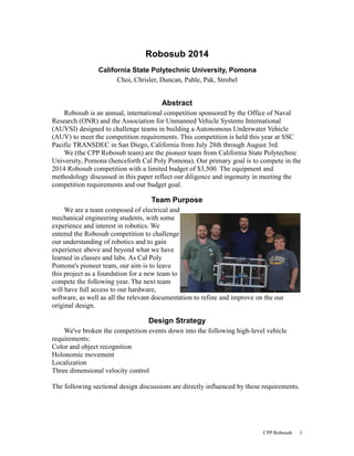
California State Polytechnic University, Pomona
Choi, Chrisler, Duncan, Pahle, Pak, Strobel
Abstract
Robosub is an annual, international competition sponsored by the Office of Naval
Research (ONR) and the Association for Unmanned Vehicle Systems International
(AUVSI) designed to challenge teams in building a Autonomous Underwater Vehicle
(AUV) to meet the competition requirements. This competition is held this year at SSC
Pacific TRANSDEC in San Diego, California from July 28th through August 3rd.
We (the CPP Robosub team) are the pioneer team from California State Polytechnic
University, Pomona (henceforth Cal Poly Pomona). Our primary goal is to compete in the
2014 Robosub competition with a limited budget of $3,500. The equipment and
methodology discussed in this paper reflect our diligence and ingenuity in meeting the
competition requirements and our budget goal.
Team Purpose
We are a team composed of electrical and
mechanical engineering students, with some
experience and interest in robotics. We
entered the Robosub competition to challenge
our understanding of robotics and to gain
experience above and beyond what we have
learned in classes and labs. As Cal Poly
Pomona's pioneer team, our aim is to leave
this project as a foundation for a new team to
compete the following year. The next team
will have full access to our hardware,
software, as well as all the relevant documentation to refine and improve on the our
original design.
Design Strategy
We've broken the competition events down into the following high-level vehicle
requirements:
Color and object recognition
Holonomic movement
Localization
Three dimensional velocity control
The following sectional design discussions are directly influenced by these requirements.
2. CPP Robosub 2
Vehicle Design Specifications
Mechanical
Frame
The frame design focused on rigidity and
weight. A rigid frame protects all the electronic
and electromechanical equipment from damage
incurred through collision. A light weight frame
allows for greater maneuverability in the water
and the use of smaller, less expensive thrusters.
Thus the frame is constructed from a light weight,
high strength T-slotted aluminum square frame.
All equipment is attached to the frame via the T-slots by screws and specialized
sliding bolts allowing for convenient modification through modularity. This has allowed
for cost-free design changes. SolidWorks modeling was used to conduct software tests for
center of mass and pressure.
Waterproofing
In order to reduce the number of holes
in our pressure vessel, we elected to drill
holes in the aluminum bolts used for heat
syncing to transfer power and
communication. Ensuring water tight
transfer of power and communication from
inside the pressure vessel to the motors and
sensors was problematic; merely sealing
around the jacket of the wires was not good
enough, because if the jacket of the wire
gets a crack in it, the water will migrate
between the wire and jacket causing a leak.
To solve this problem, we stripped a small section of every wire, put silicone and heat
shrink around it. Then we used a two part epoxy to seal that section of wire inside the
aluminum bolts.
3. CPP Robosub 3
Electrical
Hardware
Power
The system contains 3.3V, 5V, 12V, and
19V power supplies. These are obtained
through the use of separate voltage regulators
attached to a 24V battery. The regulators
supplying the motor controllers are toggled
using relays in order to allow the motors to be
switched off without shutting down the Intel
Next Unit Computing Core i3 (henceforth the
NUC), our onboard computer.
Sensors and Processing
The IMU (Inertial Measurement Unit) and pressure sensor are preprocessed using an
Arduino Nano which communicates serially with the NUC, providing linear acceleration,
rotational velocity, and three dimensional heading, and water pressure. Two Logitech
USB webcams are connected directly to the NUC.Converted Bilge Pumps were used as
thrusters due to their cost and power efficiency.
The NUC is the ideal choice for a small, low cost platform. Its form factor is very
small, and fits in almost any orientation. The processor architecture is x86, which means
that a majority of the required software is already compiled for our platform. Also,
because the NUC requires a solid state drive for storage, the platform is inherently fast
and vibration tolerant.
Cooling
Within an air tight capsule, air
cooling components is not an option. We
needed to be able to transfer the heat
generated by the components to the body
of water without creating leaks. We
mounted the components to an aluminum
plate inside the pressure vessel and used
large aluminum bolts going through the
wall of the pressure vessel to transfer the
heat to the water. O-rings were used to
seal around the bolt heads.
4. CPP Robosub 4
Software
Environment
The software is built on an x86
environment running the Linux distribution
Ubuntu 12.04. We used Python with
SimpleCV because it was both powerful
and simple to use. The entire project uses
custom python modules to make a simple
API.
All the external I/O to the vehicle is
done over 115200 baud serial lines. When
the software boots it goes through a
initialization process that checks that the
motor controllers are connected, and then
tells the motor controllers to listen, and
takes them out of a safe start mode. A similar process takes place for the IMU.
In case anything goes wrong, the software is designed so that everything is logged,
including any exceptions that occur. The real-time logging includes the motor and sensor
values being passed as well as what function was running. It also can record video and
take pictures from the onboard camera useful in vision code debugging.
Control
The vehicle is controlled by a combination of PID loops and fuzzy logic control
loops. The sensor feedback from the IMU, camera, and pressure sensor is fused within
the fuzzy logic controller and decisions are made based on a priori event knowledge and
the sensory inputs. The vehicle is able to focus on an objective and to navigate to and
interact with the objective as long as it remains in focus.
For example, the starter gate is made up of two orange poles 5 foot long and 3 inches
in diameter. They are spaced 10 feet apart, and they are floating vertically in the pool. In
order to qualify, teams must be able to go through this gate.
In order to be able to identify the gate, the software will process the images so that
only a small range of orange colors are left in the image. Then it will identify the largest
clusters of orange (because those blobs will be the poles of the gate) and then calculate
the central point of those clusters. This allows the vehicle to know where the center of the
gate is, and then to drive through we simply turn the vehicle until the center of the camera
is aligned with the center of the gate, and drive forward. We can use the IMU to estimate
how far the vehicle has traveled once the poles of the gate are no longer in view.
Next Steps
Our aim is to place with or above other first year teams in the competition this year,
and to leave a foundation for future participation by Cal Poly Pomona Robosub teams.