Superfast Broadband. The Engineering of High Speed over existing tracks
1. Super-Fast Broadband: The Engineering of High Speed over Existing
Tracks
John Marshall (UK Chief Technology Officer, ECI Telecom)
john.marshall@ecitele.com
Introduction
The growing demand for super-fast broadband services continues at a pace and provides challenges
particularly for operators responsible for the Access network. Given the significant capital investment
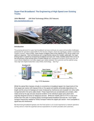
models involved, many of them have chosen to deploy Fibre to the Cabinet (FTTC) as an initial if not
optimum response. Such architectures aim to significantly reduce the metallic cable path- the major
limiting factor on speed by transporting broadband services over newly installed optical fibre as far as
the first primary cross connect point or street Cabinet with subsequent transport continuing over the
much shorter telephone (normally copper) pair cables between the customer and the cabinet using
Very high rate Digital Subscriber Loop (VDSL) technology. See Fig 1
Fig 1 FTTC Illustration
Whilst the optical fibre imposes virtually no constraints on broadband speed, the impairments of this
final copper pair section still imposes limits on the speed and stability achievable depending on its
length and the amount of background noise introduced by interference and crosstalk from other traffic
transported within the same cable sheath. These impairments are considerable and complex, often
made worse by the age and poor physical condition of the individual copper pairs which were
originally designed primarily for telephone services. Whilst the metallic path for FTTC is now much
shorter than that used for existing ADSL2 exchange based broadband services the much higher
transport frequencies needed for VDSL2 transport makes the copper pair section more susceptible to
signal loss and interference.
So maximising broadband speeds over this final section is of crucial importance to network operators
as they strive to meet the superfast service expectations of content providers and customers.
2. Constraints of Metallic Transport.
All metallic transmission systems are constrained by two fundamental impairments – noise
(essentially crosstalk and interference) which contributes to information errors and physical length
which effects signal strength. Telephone network cables generally consist of unshielded copper wire
twisted pairs, often of significant age and many with impairments including poor balance (affected by
twist span and consistency) and deteriorating electrical joints. Whilst these can often go unnoticed in
traditional telephone communication, they can be quite unforgiving to the high frequency content of
modern broadband transport. At these frequencies their relatively poor screening capability makes
them very susceptible to external electrical interference either from traffic radiating from other pairs
(crosstalk) or radiation from numerous electrical devices in their proximity including electric motors
power lines, electric fences and various radio transmissions or radio controlled devices. Customer
internal telephone wiring can also add to impairments by contributing further electrical interference
from various domestic appliances, Christmas lights and more recent sources of interference such as
Power Line Communication (PLC)
These aspects are well understood and have needed to be accommodated in traditional Exchange
based Local Loop Unbundling (LLU) Broadband delivery architectures which generally used
Asynchronous Digital Subscriber Loop (ADSL2) delivery operating in frequency ranges up to 2Mhz.
However in order to deliver the much higher speeds required of FTTC platforms VDSL2 transport is
required which operates at frequencies typically up to 17MHz. At these much higher frequencies
copper pair screening gets even worse with consequent poorer immunity to the impairments
described. Additionally the typical dimensions and architecture of customer internal wiring being
normally of a star or bridge tap nature can represent an antenna at these frequencies contributing
both attenuation spikes as well as radio interference to and from amateur radio systems. So the
challenge for network operators is to most effectively maximise broadband speed and performance
within this continuing hostile environment.
It should be noted that similar fibre based architectures used by Cable operators popularly call Hybrid
Fibre Coax or Cable/DOCIS systems (not the subject of this article) are less impacted by impairments
discussed above since the final metallic section utilises coaxial cable pairs which are designed to
have much superior performance to unshielded copper pairs at the frequencies concerned.
VDSL2 Technology meeting the challenge.
VDSL2 is generally regarded as the most effective and robust transport technology for carrying
broadband content over this difficult final link. The Digital Subscriber Line Access Multiplexer
(DSLAM) incorporated within the cabinet accordingly translates the broadband optical transport into
VDSL2 for onward transport to the customer’s premises over the metallic path as illustrated in Fig 1
Because of the variation in length and condition of each customer’s line, the DSLAM implements an
synchronisation process with the customers broadband modem when service is first initialised
(known as ‘train up’). This enables the link to stabilise on an optimum broadband speed which can
deliver reasonably error free performance within the line conditions prevailing. A short line with low
noise could consequently train up to a high broadband speed (typically 50Mb +) whereas a long line
with high noise may only train up to 10Mb/s or lower. In this respect performance and stability needs
to be balanced appropriately with speed in the context of the service type being provided, For
example E-mail and file transfer services may be optimised for high speed being reasonably resilient
to moderate levels of errors from a customer perspective, whilst other services such as video may
deteriorate quite significantly with relatively few errors. See Fig 2. So a level of sophistication needs
to be incorporated into the way line speed and performance is determined, implemented and
maintained throughout the period of customer service. This has to include regular adjustment as line
conditions and impairment alters with time.
3. Fig 2 Effect of errors on Video Service
Maintaining and Optimising Broadband performance
So whilst successful DSL service initialisation sets the optimum broadband speed for the line, this
performance needs to be regularly maintained and adjusted if and when line conditions change For
instance, background noise levels can gradually increase as more customer broadband lines get
introduced to the cable binder increasing the level of cross talk. Unpredictable bursts of Impulse noise
can also occur spontaneously or at periodically intervals and not necessarily at the time of
initialisation. Whilst these may be successfully contained within the operational performance margins
set by the DSLAM, line deterioration beyond these margins will force a DSLAM into a retrain cycle
causing a service interruption followed by potential stabilization at a sub optimum speed.
Management mechanisms are therefore needed to ensure broadband performance is maintained in
an optimum state. They are designed to either minimise or eliminate noise interference and
continuously monitor and dynamically adjust the VDSL2 transport speed and performance to best
accommodate the noise that still prevails. Such mechanisms can exist within the VDSL2 technology
itself (DSLAM based) or within operational management processes of the broadband access network
(OSS based). Each have specific attributes and applications and most come at a slight overhead cost
in terms of speed reduction or delay. Network operators usually implement a mixture of the two and
the most popular ones are covered below.
Forward Error Correction (FEC)
This is a technique used for controlling errors which get introduced into the VDSL data stream by
cable noise or crosstalk. Essentially the DSLAM encodes the broadband information message into
special frames (termed Cyclic Redundancy Check [CRC] frames) in a redundant manner by using an
error-correcting code (ECC) such as Reed Solomon1
or Hamming codes2
. This enables the
Customers modem receiver to detect and limit the number of errors that may occur anywhere in the
message, and often to correct these errors without need for retransmission of data. This can be an
effective mechanism where errors introduced by noise are not excessive
Interleaving
Interleaving introduced by the DSLAM is often used to improve the performance of FEC and is
particularly effective where bursts of impulse noise are a significant cause of interference to the
broadband data. The interleaving technique consists of “chopping” a stream into multiple segments
and shuffling source symbols across several codes as illustrated below. When impulse noise occurs,
and affects a few symbols (L corrupted bytes), only part of the original “N bytes” stream gets affected
(minimal impact), allowing the FEC mechanism to “correct” those errors. Without interleaving, too
many errors would be generated by the impulse noise and FEC won’t be able to fix them. The depth
4. of interleaving can be varied with a greater depth improving immunity at the expense of some latency
being introduced to the transmission.
Fig 3 Interleaving Technique
Physical Layer Retransmission
Whilst the above two mechanisms of FEC and Interleaving provides a fairly robust method of
protecting the VDSL transmission from the effects of impulse noise, many broadband network
operators are now considering physical layer retransmission (Re-Tx) as an additional technique
which can be more efficient. It utilises an Automatic Repeat Request (ARQ) protocol involving the
incorporation of a retransmission buffer in the DSLAM transmitter and a complementary buffer in the
customers modem. When a received frame gets corrupted by noise, the transmitter side will
retransmit the same information again. As such its advantage over FEC and interleaving is that it only
generates an overhead when a corruption actually exists on the line
Vectoring
This mechanism has been described in more detail in earlier articles
3
. It is a powerful mechanism
which effectively removes all the crosstalk noise introduced by other customer lines. This is achieved
by a vectoring engine within the DSLAM which measures the interference from all copper pairs within
a cable or binder and injects a corresponding anti-phase signal to cancel this interference at the
customer end as illustrated below
Fig 4 Vectoring Concept
Eliminating all of the crosstalk noise in this way facilitates lines to train up to significantly higher
speeds as a consequence of the much larger S/N margin created. Typically lines with normal speeds
of 50Mb/s can experience a doubling of speed when vectoring is implemented. Vectoring also offers
valuable protection against ‘speed erosion’ where customers speeds can decline over time as density
of broadband lines (and hence crosstalk noise) increases.
Currently, in order for vectoring to be most effective, all the lines within a given cable need to be
allocated to a single vectored group (i.e., lines must be visible to a single vectoring engine). This is
readily achieved when the cabinet contains a single DSLAM. However in Sub Loop Unbundling
5. (SLU) environments where more than one DSLAM (and vectoring engine) can coexist within the
cabinet the benefits of vectoring can be reduced and work continues in this area.
Seamless Rate Adaptation (SRA)
Seamless Rate Adaptation (SRA) is a DSLAM mechanism currently under consideration which
dynamically adapts the broadband speed depending upon the current condition of the line. Normally a
significant deterioration in the line S/N margin can result in a line retrain to a lower speed with
associated interruption to service. With SRA, line conditions are constantly monitored and any
increases/decreases in SNR results in an automatic increase/decrease in the line speed without
having to go through the retrain sequence, hence achieving a much smoother management of the
customer service. Line speed will always be at the highest possible rate depending upon the
set target SNR, which is particularly useful if the line deterioration is only transient, as SRA will ensure
that speed will increase as line conditions improve.
Mechanisms within Network Operational Management.
In addition to the technology mechanisms described, network operators and service providers will
often consider additional mechanisms within their network management operational process to
ensure maximum speed and performance. These often utilise and complement the technology
mechanisms. Dynamic Line Management (DLM) is the most popular of these. Operators also employ
a rigorous control on power levels emitted by DSLAMs and modems in relation to their position in the
network in order to ensure optimum performance for all customers within power spectral density
(PSD) limits set by nationally agreed Access Network Frequency Plans (ANFP).
Dynamic Line Management (DLM)
This is usually a powerful OSS based operational system which works in conjunction with the DSLAM
based management mechanisms to further ensure speed performance and stability of customers
lines are maintained in the optimum state. It uses OSS management links with the DSLAM to draw
down detailed status of numerous line parameters which are continuously monitored. This can include
historic data on for example noise levels, signal loss, error performance and retrain cycles which
have taken place. Sophisticated algorithms work on this data to establish and implement any
subsequent changes deemed necessary to DSLAM operational parameters and profiles to maintain
optimum performance and stability of the customer’s line. This can include introducing and varying
levels of interleaving, switching on retransmission or varying the banded frequency profile governing
the max and min speed the line can operate within. The DLM process flow is illustrated below.
Fig 5 DLM Concept
6. The DLM monitoring cycle usually operates on a periodicity of days rather than hours in order to allow
any new profile change to settle and establish itself before any further action is taken.
Putting VDSL2 Achievements in Perspective
It is somewhat of a testament to the above technology mechanism and operational processes that,
together, they manage to secure acceptably high broadband speeds over this often aging and
deteriorating copper infrastructure between the cabinet and the customer’s premises.
The lower curve in Fig 6 illustrates typically the speeds which FTTC connected customers can enjoy
depending on their distance from the cabinet and in the presence of average crosstalk noise
expected. This indicates that speeds in excess of 50Mb/s are possible for customers within 400m of
the cabinet which is often a sizable proportion (typically 60%) of the network operator’s customer
footprint. The higher curve indicates a further dramatic improvement which an operator can achieve
with the implementation of vectoring, pushing for example 50Mb/s customers up to in excess of
100Mb/s and extending the 50Mb/s footprint out as far as 1Km from the cabinet.
Fig 6 Typical Rate versus Reach : Vectored and Non Vectored Performance
It is important of course to put this into the wider context acknowledging that these curves also show
performance declining with increasing distance and therefore not all customers will have their super-
fast broadband expectations satisfied by FTTC architectures. Typically customers on the FTTC
extremities (> 2km distance from the cabinet) will likely struggle to experience better than 10Mb/s
speeds and we cannot overlook the 5-10% of customers who remain outside practical catchment
areas of FTTC and therefore continue to live with sub 2Mb/s speeds.
Squeezing much more out VDSL2 technology to address this seems somewhat limited and whilst
interesting R&D studies continue particularly in areas such as Dynamic Spectrum Management
(DSM)
4
, the law of diminishing returns is becoming apparent. We also cannot ignore the continuing
7. trend for even higher broadband speeds over the next decade brought about by more bandwidth
hungry services and multi session growth in customer premises.
So where to next?
There is a proverb which comes to mind which says ‘wisdom consists not so much of knowing what to
do as knowing what to do next.
So given the continued thirst for even faster broadband speeds and recognising the
national/regulatory pressures to improve uniformity and consistency of speeds across the entire
broadband network, operators need to seriously consider how best to enhance or migrate their FTTC
architectures to best effect. The obvious approach is to shrink the impairing metallic path still further
or eliminate it all together. There are a number of candidate architectures already under consideration
and the real challenge will be one of making the right choice at the right time given the uncertainties of
revenue forecast against the associated significant capital investments involved.
Two topical candidate architectures are Fibre to the Dp (FTTDp) where the fibre from the exchange is
extended still further beyond the cabinet to the last distribution point in the network Dp or Telephone
pole (reducing the copper section to 100m or less) and Fibre To the Premises FTTP where fibre is
extended all the way to the home eliminating copper infrastructure entirely. These are illustrated
below.
Fig 7 Candidate architectures for Higher speed
FTTP may be more capitally expensive in terms of depth of fibre installation and the associated
customer premises conversion costs involved but it does future proof networks for almost unlimited
broadband speeds and being totally passive has the merits of potentially lower network operational
costs. FTTDp has the benefits of potentially lower fibre capital expenditure costs and possibly no
customer premises conversion costs whilst offering significant speeds of up to 1Gb/s (because of the
much shorter copper reach <0.1K). DSL technology optimised for this architecture (G.Fast) is
currently going through standardisation 5
.
Operator choices are likely to be influenced by the extent of investments already made in FTTC as
well as the strategies they have already put in place to hedge against evolution such as employing
8. Integrated Optical Line Terminations (I-OLTs) and prudent fibre planning practices which cater better
for mixed architectures and deeper fibre penetration at a later date.
Conclusion
Super-fast broadband speeds in excess of 50Mb/s are now achievable from well-engineered FTTC
broadband architectures even though a significant proportion of the transport continues to be
carried over existing and often ageing telephone copper pairs between the cabinet and customer
premises. This is a tribute to the performance management mechanisms engineered within the
VDSL2 technology itself and the associated operational DLM practices implemented by network
operators. As a consequence, noticeable step fold improvements in headline broadband speeds
have been established across the bulk of national broadband footprints.
However FTTC architectures do not fully insulate operators from future growth in speed demand or
national/regulatory pressures for more uniformity and consistency of service. Performance inevitably
continues to decline with increasing copper distance from the cabinet, meaning that a proportion of
customers will struggle to experience high speeds and there remain customers outside the practical
catchment area of FTTC who continue to experience much less.
So network operators need to remain vigilant in considering where they go to next with their fibre
based network investments. There are a number of candidate architectures becoming popular which
can move speeds much higher and towards greater uniformity of coverage but decision making has
the usual challenges of timing and choice to be made within uncertain forecasts . Changes in
customer broadband usage and potential inroads made by alternative technologies such as radio
/mobile will continue to populate the region of the ‘known unknowns’. So the crystal ball in this area
remains as elusive as ever and network operators must therefore continue to plan accordingly for
uncertainty.
1. Cipra, Barry A. (1993), "The Ubiquitous Reed–Solomon Codes", SIAM News 26 (1)
2. Hamming, R. W. (April 1950). "Error Detecting and Error Correcting Codes".Bell System Tech.
J. (USA: AT&T) 29 (2): 147–160. Retrieved 4 December 2012
3. Marshall. J and Benchaim. D. The Rural Challenge for High Speed Broadband. ITP Journal,
Volume 7 Part 2 2013
4. John M. Cioffi, et al. Dynamic Spectrum Management for Next-Generation DSL Systems IEEE
Communications Magazine • October 2002
5. ITU-T G.9700 and G.9701 - fast access to subscriber terminals
END
October 2014