Electrical Component Testing Guide in 40 Characters
1. Electrical Component Testing
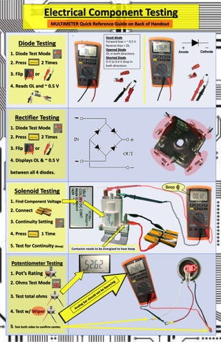
Diode Testing
1. Diode Test Mode
2. Press 2 Times
3. Flip or
4. Reads OL and ~ 0.5 V
Rectifier Testing
1. Diode Test Mode
2. Press 2 Times
3. Flip or
4. Displays OL & ~ 0.5 V
between all 4 diodes.
Solenoid Testing
1. Find Component Voltage
2. Connect
3. Continuity Setting
4. Press 1 Time
5. Test for Continuity (Beep)
Beep
Potentiometer Testing
1. Pot’s Rating
2. Ohms Test Mode
3. Test total ohms
4. Test w/ Wiper
5. Test both sides to confirm center.
MULTIMETER Quick Reference Guide on Back of Handout
Contactor needs to be energized to hear beep
Good diode
Forward bias = ~ 0.5 V
Reverse bias = OL
Opened Diode
OL in both directions
Shorted Diode
O V to 0.4 V drop in
both directions
2. MULTIMETER ROTARY SWITCH MULTIMETER DISPLAY FUNCTION BUTTON
Select the Ohms, Continuity,
Diode Switch.
Ohms = Press 0 Times
Continuity + = Press 1 Time
Diode = Press 2 Times
N/O & N/C Switches
1. Continuity Test
2. Press 1 Time
3. N/O and N/C
Relay Testing
1. Find Component Voltage
2. Continuity Test
3. Press 1 Time
4. Read Diagram
87a = N/C and 87 = N/O
Fuse and Breaker Testing
1. Continuity Test
2. Press 1 Time
3. Visually Inspect Fuses
4. For Continuity
Common
N/O
N/C
Electrical Component Testing
MULTIMETER Quick Reference Guide Below
Continuity +
Ohms Test
Analog Bar
Continuity Test
Used when you cannot
see your display. The
beep indicates a solid
connection. Using
Ohms is more exact.
Diode Test
Applies a dynamic
voltage to the diode
which tests more
accurately then using
the ohms setting.
Test Both
If the analog bar bounces
too much Potentiometer
is bad.
Ambient Circuit
Breaker
Fuses
Thermal Fuse
Circuit
Breakers
Thermal
Breaker
Contactor needs to be energized to hear beep on N/O Circuit