1. DIGITALMULTIMETERS&SYSTEMS
A Greater Measure of Confidence
www.keithley.com
1.888.KEITHLEY (U.S. only)
A Tektronix Company
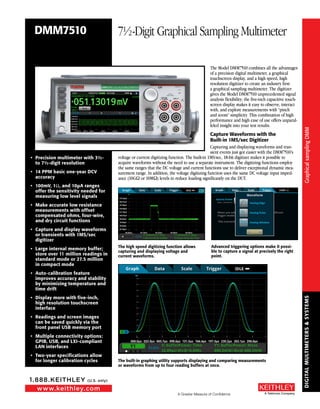
The Model DMM7510 combines all the advantages
of a precision digital multimeter, a graphical
touchscreen display, and a high speed, high
resolution digitizer to create an industry first:
a graphical sampling multimeter. The digitizer
gives the Model DMM7510 unprecedented signal
analysis flexibility; the five-inch capacitive touch-
screen display makes it easy to observe, interact
with, and explore measurements with “pinch
and zoom” simplicity. This combination of high
performance and high ease of use offers unparal-
leled insight into your test results.
Capture Waveforms with the
Built-in 1MS/sec Digitizer
Capturing and displaying waveforms and tran-
sient events just got easier with the DMM7510’s
voltage or current digitizing function. The built-in 1MS/sec, 18-bit digitizer makes it possible to
acquire waveforms without the need to use a separate instrument. The digitizing functions employ
the same ranges that the DC voltage and current functions use to deliver exceptional dynamic mea-
surement range. In addition, the voltage digitizing function uses the same DC voltage input imped-
ance (10GΩ or 10MΩ) levels to reduce loading significantly on the DUT.
• Precision multimeter with 3½-
to 7½-digit resolution
• 14 PPM basic one-year DCV
accuracy
• 100mV, 1Ω, and 10µA ranges
offer the sensitivity needed for
measuring low level signals
• Make accurate low resistance
measurements with offset
compensated ohms, four-wire,
and dry circuit functions
• Capture and display waveforms
or transients with 1MS/sec
digitizer
• Large internal memory buffer;
store over 11 million readings in
standard mode or 27.5 million
in compact mode
• Auto-calibration feature
improves accuracy and stability
by minimizing temperature and
time drift
• Display more with five-inch,
high resolution touchscreen
interface
• Readings and screen images
can be saved quickly via the
front panel USB memory port
• Multiple connectivity options:
GPIB, USB, and LXI-compliant
LAN interfaces
• Two-year specifications allow
for longer calibration cycles
DMM7510 7½-Digit Graphical Sampling Multimeter
The high speed digitizing function allows
capturing and displaying voltage and
current waveforms.
Advanced triggering options make it possi-
ble to capture a signal at precisely the right
point.
The built-in graphing utility supports displaying and comparing measurements
or waveforms from up to four reading buffers at once.
GraphicalsamplingDMM
GraphicalsamplingDMM
2. DIGITALMULTIMETERS&SYSTEMS
www.keithley.com
1.888.KEITHLEY (U.S. only)
A Greater Measure of Confidence A Tektronix Company
Make Demanding Measurements with Confidence
The Model DMM7510’s design makes the most of Keithley’s low level measurement expertise.
Features like the low noise input stage and the 32-bit A-to-D converter allow this instrument to
deliver DC accuracies typically only found in metrology-grade instrumentation—but at about half
the price of those solutions. The Model DMM7510’s 100mV, 10Ω, and 10µA ranges deliver the
sensitivity needed to measure low signals with confidence when characterizing today’s demanding
electronic designs. In addition to one- and two-year accuracy specifications, an auto-calibration
function ensures greater accuracy between calibration cycles.
2µV
1µV
0µV
–1µV
–2µV
Volts
6½ Digit 8½ Digit DMM7510
One Power Line Cycle
Noise Performance
The DMM7510 provides noise performance
equivalent to or better than many 8½-digit DMMs.
Comparison of the Model DMM7510’s 1V DC noise performance with that of typical 6½- and
8½-digit multimeters. All data was taken at 1 NPLC with a low thermal short applied to
the input.
15 Measurement Functions
The DMM7510 provides 15 basic measurement functions. In addition to the digitizing voltage and
current functions, it includes capacitance, ACV and ACI, temperature (RTD, thermistor, and thermo-
couple), 2- and 4-wire resistance, dry circuit ohms, period, frequency, diode test, and DC voltage
ratio. The instrument’s flat menu structure allows for fast configuration and improves usability. Its
intuitive design lets you learn how to operate the instrument and begin making device measurements
faster and with greater confidence.
RTD, Thermistor, Thermocouple
Ordering Information
DMM7510 7½-Digit Graphical
Sampling Multimeter
DMM7510-NFP
7½-Digit Graphical
Sampling Multimeter,
with No Front Panel
DMM7510-RACK
7½-Digit Graphical
Sampling Multimeter,
with No Handle
DMM7510-NFP-RACK
7½-Digit Graphical
Sampling Multimeter,
with No Front Panel
and No Handle
Accessories Supplied
1756 Test Leads
USB-B-1 USB Cable, Type A to
Type B, 1m (3.3 ft)
CA-180-3A TSP-Link/Ethernet Cable
Documentation CD
DMM7510 QuickStart Guide
Test Script Builder Software
(available at www.keithley.com )
KickStart Startup Software
(available at www.keithley.com)
LabVIEW and IVI Drivers (available
at www.keithley.com)
DMM7510 7½-Digit Graphical Sampling Multimeter
GraphicalsamplingDMM
GraphicalsamplingDMM
3. DIGITALMULTIMETERS&SYSTEMS
A Greater Measure of Confidence
www.keithley.com
1.888.KEITHLEY (U.S. only)
A Tektronix Company
DMM7510 7½-Digit Graphical Sampling Multimeter
DMM7510 Measurement Capabilities
DC Voltage
AC Voltage
DC Current
AC Current
Resistance (2-wire)
Resistance (4-wire)
Dry Circuit Resistance
Capacitance
Period
Frequency
Digitize Voltage
Digitize Current
10nV
100nV
Logarithmic Scale
Linear Scale
1pA
1nA
100nΩ
1µΩ
0.1pF
–200°C
–80°C
–200°C
–200°C
1820°C
150°C
850°C
850°C
2µs
3Hz
1µV
0.1nA
1010V
707VRMS
10.1A
10.1A
1.2GΩ
2.4kΩ
1µΩ 1.2GΩ
1.2mF
330ms
500kHz
1010V
10.1A
1f 1p 1n 1µ 1m 1 1k 1M 1G
Thermocouple
Thermistor
3-Wire RTD
4-Wire RTD
–500° 0° 500° 1000° 1500° 2000°
Designed for Higher Testing Productivity
In addition to its advanced touchscreen, the Model DMM7510’s front panel offers a variety of features
that enhance its speed, user-friendliness, and learnability, including a USB 2.0 memory I/O port, a
HELP key, a rotary navigation/control knob, and front/rear input selector button. All front-panel but-
tons are backlit to enhance visibility.
Online HELP is
just a button
press away
Store test
results and
screen images
quickly via
the USB 2.0
Memory port Lower swipe screen
speeds access to
often-used features
Five-inch touchscreen
displays more information
simultaneously
Rotary control knob
offers an alternative to
touchscreen navigation
Front/rear input
selector
ACCESSORIES AVAILABLE
TEST LEADS AND PROBES
1752 Premium Safety Test Lead Kit
1754 2-Wire Universal 10-Piece Test Lead Kit
1756 General Purpose Test Lead Kit
5804 Kelvin (4-Wire) Universal 10-Piece Test Lead Kit
5805 Kelvin (4-Wire) Spring-Loaded Probes
5806 Kelvin Clip Lead Set
5808 Low Cost Single-pin Kelvin Probe Set
5809 Low Cost Kelvin Clip Lead Set
8606 High Performance Modular Probe Kit
8610 Low Thermal Shorting Plug
REPLACEMENT FUSES
DMM7510-FUSE-10A 11A Current Fuse For DMM7510
DMM7510-FUSE-3A 3.5A Current Fuse For DMM7510
CABLES, CONNECTORS, ADAPTERS
CA-18-1 Shielded Dual Banana Cable, 1.2m (4 ft.)
COMMUNICATION INTERFACES & CABLES
KPCI-488LPA IEEE-488 Interface for PCI Bus
KUSB-488B IEEE-488 USB-to-GPIB Interface Adapter
7007-1 Shielded GPIB Cable, 1m (3.2ft)
7007-2 Shielded GPIB Cable, 2m (6.5ft)
CA-180-3A CAT5 Crossover Cable for TSP-Link / Ethernet
USB-B-1 USB Cable, Type A to Type B, 1m (3.3 ft)
TRIGGERING AND CONTROL
2450-TLINK DB-9 to Trigger Link Connector Adapter
8501-1 Trigger Link Cable, DIN-to-DIN, 1m (3.2 ft.)
8501-2 Trigger Link Cable, DIN-to-DIN, 2m (6.5 ft.)
8503 DIN-to-BNC Trigger Cable
RACK MOUNT KITS
4299-8 Single Fixed Rack Mount Kit
4299-9 Dual Fixed Rack Mount Kit
4299-10 Dual Fixed Rack Mount Kit. Mount One
DMM7510 and One Series 26xxB Instrument
4299-11 Dual Fixed Rack Mount Kit. Mount One
DMM7510 and One Instrument from Series
2400, Series 2000, etc.
4299-12 Dual Fixed Rack Mount Kit. Mount One
DMM7510 and One Keysight Instrument.
DMM7510-BenchKit
Ears and Handle for DMM7510-NFP-RACK and
DMM7510-RACK Models
GraphicalsamplingDMM
GraphicalsamplingDMM
4. DIGITALMULTIMETERS&SYSTEMS
www.keithley.com
1.888.KEITHLEY (U.S. only)
A Greater Measure of Confidence A Tektronix Company
DMM7510 7½-Digit Graphical Sampling Multimeter
SERVICES AVAILABLE
EXTENDED WARRANTIES
DMM7510-EW 1 Year Factory Warranty Extended
to 2 Years from Date of Shipment
DMM7510-3Y-EW 1 Year Factory Warranty Extended
to 3 Years from Date of Shipment
DMM7510-5Y-EW 1 Year Factory Warranty Extended
to 5 Years from Date of Shipment
DMM7510-NFP-EW 1 Year Factory Warranty Extended
to 2 Years from Date of Shipment
DMM7510-NFP-3Y-EW 1 Year Factory Warranty Extended
to 3 Years from Date of Shipment
DMM7510-NFP-5Y-EW 1 Year Factory Warranty Extended
to 5 Years from Date of Shipment
CALIBRATION CONTRACTS
C/DMM7510-3Y-17025 KeithleyCare® 3 Year ISO-17025
Calibration Plan
C/DMM7510-3Y-DATA KeithleyCare 3 Year Calibration w/
Data Plan
C/DMM7510-3Y-STD KeithleyCare 3 Year Std Calibration
Plan
C/DMM7510-5Y-17025 KeithleyCare 5 Year ISO-17025
Calibration Plan
C/DMM7510-5Y-DATA KeithleyCare 5 Year Calibration w/
Data Plan
C/DMM7510-5Y-STD KeithleyCare 5 Year Std Calibration
Plan
C/DMM7510-NFP-3Y-17025 KeithleyCare 3 Year ISO-17025
Calibration Plan
C/DMM7510-NFP-3Y-DATA KeithleyCare 3 Year Calibration w/
Data Plan
C/DMM7510-NFP-3Y-STD KeithleyCare 3 Year Std Calibration
Plan
C/DMM7510-NFP-5Y-17025 KeithleyCare 5 Year ISO-17025
Calibration Plan
C/DMM7510-NFP-5Y-DATA KeithleyCare 5 Year Calibration w/
Data Plan
C/DMM7510-NFP-5Y-STD KeithleyCare 5 Year Std Calibration
Plan
C/NEW DATA Calibration Data for New Units
C/NEW DATA ISO ISO-17025 Calibration Data for
New Units
Easily accessible
current fuses
Measure Complete and
External Trigger (Model 8503
BNC Accessory Available)
GPIB interfaceSix user-defined
digital I/Os
USB 2.0
interface
LAN/LXI
interface
The rear panel of the DMM7510 provides connections and controls that simplify configuring
multi-instrument test solutions, including input connectors, remote control interfaces (GPIB,
USB 2.0, and LXI/Ethernet), a D-sub 9-pin digital I/O port (for internal/external trigger signals
and handler control), and TSP-Link® jacks for connecting to other TSP-enabled instruments.
Flexible System Integration and Programming
To offer users maximum programming flexibility and simplify configuring multi-instrument test
systems, the DMM7510 includes Keithley’s powerful Test Script Processor (TSP®) system and SCPI
programming mode. The embedded scripting capability allows running powerful test scripts directly
on the instrument, without the need for an external PC controller. These test scripts are complete
test programs based on an easy-to-use yet highly efficient and compact scripting language, Lua
(www.lua.org). Scripts are a collection of instrument control commands and/or program state-
ments. Program statements control script execution and provide facilities such as variables, functions,
branching, and loop control. This allows you to create powerful measurement applications with
significantly reduced development times. Test scripts can contain any sequence of routines that are
executable by conventional programming languages (including decision-making algorithms), so
the instrument can manage every facet of the test without the need to communicate with a PC for
decision-making. This eliminates delays due to GPIB, Ethernet or USB traffic congestion and greatly
improves overall test times.
TSP technology also offers “mainframe-less channel expansion.” The TSP-Link channel expansion bus
and a 100 Base T Ethernet cable allow connecting multiple DMM7510s with other TSP-enabled instru-
ments in a master-slave configuration so they operate as a single integrated system. These instru-
ments include the Model 2450 and Model 2460 Interactive SourceMeter® SMU instruments, Series
2600B SourceMeter SMU instruments, and the Series 3700A Switch/Multimeter systems. TSP-Link
supports up to 32 units per GPIB or IP address, so it’s easy to scale a system to fit the requirements of
an application.
A standard SCPI programming mode supports taking advantage of all of the DMM7510’s new features
when programming remotely. In addition, the instrument is code-compatible with the SCPI language,
which many other DMMs use. This code compatibility avoids the need to rewrite code that is normal-
ly associated with upgrading to a new instrument with new capabilities.
GraphicalsamplingDMM
GraphicalsamplingDMM
5. DIGITALMULTIMETERS&SYSTEMS
A Greater Measure of Confidence
www.keithley.com
1.888.KEITHLEY (U.S. only)
A Tektronix Company
DMM7510 7½-Digit Graphical Sampling Multimeter
Free Instrument Control Startup Software
Keithley’s KickStart instrument control startup software lets you begin taking measurements
in minutes.
KickStart combines a wide range of functions to
enhance testing productivity:
• Instrument-specific UI panel
• Manual instrument configuration
• Basic reading display and tabular
viewing of data
• Datalogging
• Native X-Y data graphing
• Panning & zooming
• Basic statistics (native to instrument, mX+b)
• Saving/exporting data
• Connect using any remote interface
(GPIB, USB, LAN)
• Save instrument setups
• Screenshot capture
• Command line dialog box
Ready-to-use Instrument Drivers
Simplify Programming
Need to create your own customized appli-
cation software? Native National Instruments
LabVIEW®, IVI-C, and IVI-COM drivers are avail-
able for downloading at www.keithley.com to
simplify the programming process.
GraphicalsamplingDMM
GraphicalsamplingDMM
6. DIGITALMULTIMETERS&SYSTEMS
www.keithley.com
1.888.KEITHLEY (U.S. only)
A Greater Measure of Confidence A Tektronix Company
DMM7510 7½-Digit Graphical Sampling Multimeter
Specification Conditions
This document contains specifications and supplemental infor-
mation for the Model DMM7510 7½-Digit Graphical Sampling
Multimeter instrument. Specifications are the standards against
which the Model DMM7510 is tested. Upon leaving the factory,
the Model DMM7510 meets these specifications. Supplemental
and typical values are nonwarranted, apply at 23°C (73°F), and
are provided solely as useful information. Measurement accura-
cies are specified at the Model DMM7510 terminals under these
conditions:
• Temperature 23° ±5°C, 5% to 80% relative humidity, non-
condensing.
• After a 90-minute warmup period.
• 1 PLC or 5 PLC; for NPLC settings less than 1 PLC, add appro-
priate ppm of range for peak noise uncertainty from the RMS
noise table.
• Autozero enabled unless otherwise noted.
• Remote sense operation or properly zeroed local operation.
• Calibration period: One year or two years (calibration period
may vary depending on customer requirements).
• TACAL = Ambient temperature of last automatic calibration.
• TCAL = Ambient temperature of last external calibration;
factory calibration performed at 23° ±1°C.
DC Voltage
ACCURACY (INPUT IMPEDANCE AUTO)
Range 1 Resolution
Input
Impedance 2
Accuracy ±(ppm of reading + ppm of range)
24 Hour
TCAL ±1°C 2
90 Day
TCAL ±5°C
1 Year
TCAL ±5°C
2 Year
TCAL ±5°C
Temperature
Coefficient 3
100.00000 mV4 10 nV
>10 GΩ or
10 MΩ ±1 %
6 + 9 12 + 9 18 + 9 29 + 9 0.1 + 2.5
1.0000000 V 4 100 nV
>10 GΩ or
10 MΩ ±1 %
4 + 1 9 + 2 15+ 2 26 + 2 0.1 + 0.5
10.000000 V4 1 µV
>10 GΩ or
10 MΩ ±1 %
2 + 0.7 9 + 1.2 14 + 1.2 22 + 1.2 0.1 + 0.05
100.00000 V4 10 µV 10 MΩ ±1 % 8 + 3
(18 + 5)5 (22 + 5)5 (30 + 5)5 (0.15 + 0.05)5
35 + 5 40 + 5 45 + 5 2.0 + 0.5
1000.0000 V4, 6 100 µV 10 MΩ ±1 % 8 + 3
(19 + 5)5 (23 + 5)5 (31 + 5)5 (0.15 + 0.05)5
35 + 5 40 + 5 45 + 4 2.0 + 0.5
RMS NOISE (additional peak noise uncertainty) 7
• Applies to ±ppm of range.
• Peak noise uncertainty is included in DC specifications for ≥1 PLC.
• Add peak noise uncertainty to measurements for <1 PLC.
• Input impedance set to Auto.
Examples:
• 10V at 0.006 PLC: 1.2 (from Accuracy table) + 11 (additional peak noise uncertainty) = 12.2 ppm of range.
• 10V at 1 PLC: 1.2 + 0 = 1.2 ppm of range.
NPLC Digits 100 mV 1 V 10 V 100 V 1000 V
5 7½ 0.5 0.08 0.06 0.3 0.06
1 7½ 0.5 0.09 0.07 0.4 0.07
0.28 6½ 2 (10) 0.2 (1.6) 0.1 (1.1) 1.1 (9.4) 0.1 (1)
0.2 6½ 2 (12) 0.2 (1.6) 0.1 (1) 1.1 (8.9) 0.2 (1.1)
0.06 5½ 3 (17) 0.4 (2.7) 0.3 (2.1) 3 (17) 0.3 (2.4)
0.006 4½ 6 (42) 3 (18) 1 (11) 20 (100) 3 (18)
0.0005 3½ 30 (220) 20 (150) 20 (130) 120 (690) 20 (150)
DC VOLTAGE SENSE ACCURACY
Accuracy ±(ppm of reading + ppm of range)
Range
24 Hour
TCAL ±1°C
90 Day
TCAL ±5°C
1 Year
TCAL ±5°C
2 Year
TCAL ±5°C
Temperature
Coefficient 9
100.00000 mV 6 + 14 12 + 14 18 + 14 29 + 14 0.1 + 2.5
1.0000000 V 4 + 1.5 9 + 3 15 + 3 26 + 3 0.1 + 0.5
10.00000 V 2 + 1.0 9 + 1.8 14 + 1.8 22 + 1.8 0.1 + 0.05
DC VOLTAGE RATIO
For input signals ≥1% of the range, ratio accuracy = ±[[VINPUT ppm of reading + VINPUT ppm of range * (VINPUT range/VINPUT input)] +
[VSENSE ppm of reading + VSENSE ppm of range * (VSENSE range/VSENSE input)]].
1. 20% overrange on all ranges except 1% for 1000V range.
2. Relative to calibration accuracy.
3. Add per degree from TCAL ±5°C.
4. When properly zeroed using the Rel function with external cables.
5. Specified within 30 days of autocalibration, TOPER ±5°C from TACAL.
6. For signal levels greater than 500V, add 0.02 ppm/V to the ppm of the readings specification for measurements exceeding 500V.
7. Noise values are based on 1000 readings with autozero on and using low thermal 4-wire short. VRMS noise is typical. Additional
peak noise is guaranteed.
8. With line sync on.
9. Add per degree from TCAL ±5°C.
ModelDMM7510condensedspecifications
ModelDMM7510condensedspecifications
7. DIGITALMULTIMETERS&SYSTEMS
A Greater Measure of Confidence
www.keithley.com
1.888.KEITHLEY (U.S. only)
A Tektronix Company
DMM7510 7½-Digit Graphical Sampling Multimeter
DC VOLTAGE CHARACTERISTICS
ADC LINEARITY: 1.0 ppm of reading + 1.0 ppm of range.
INPUT IMPEDANCE:
100mV to 10V Ranges: Selectable >10GΩ ||<400pF (auto) or 10MΩ ±1% (10MΩ).
100V to 1000V Ranges: 10MΩ ±1%.
INPUT BIAS CURRENT: <50pA at 23°C under the following conditions: Autozero off or input
impedance 10MΩ.
COMMON MODE CURRENT: <2.1µA peak-peak in 1MHz bandwidth.
<100nA peak-peak in 1kHz bandwidth.
COMMON MODE VOLTAGE: 500Vpeak LO terminal to chassis maximum.
DC VOLTAGE AUTOZERO OFF ERROR:
For ±1°C and ≤10 minutes, add ±(8ppm of reading + 15µV).
10. Specifications are for 4-wire resistance, offset compensation on for ≤10kΩ measurements, and
offset compensation off for ≥10kΩ measurements. 1Ω range is 4-wire only. For 2-wire, with
Rel, add 50mΩ to ppm of range uncertainty. Without Rel and with Model 1756 test leads, add
100mΩ to ppm of range uncertainty.
11. 20% overrange on all ranges.
12. Test current with offset compensation off, ±5%.
13. Relative to calibration accuracy.
14. Add per degree from TCAL ±5°C.
15. Specifications are for external cable and load capacitance <1nF.
16. For offset compensation on, add 10ppm uncertainty to ppm of reading.
17. For 4-wire 1MΩ, open lead detector on, add 10 ppm uncertainty to ppm of reading.
18. Specified for <10% lead resistance mismatch in HI and LO.
19. Specifications are for 4-wire resistance, offset compensation on for ≤10kΩ measurements, and
offset compensation off for ≥10kΩ measurements. 1Ω range is 4-wire only. For 2-wire, with
Rel, add 50mΩ to ppm of range uncertainty. Without Rel and with Model 1756 test leads, add
100mΩ to ppm of range uncertainty.
20. 20% overrange on all ranges.
21. Test current with offset compensation off.
22. Relative to calibration accuracy.
23. Add per degree from TCAL ±5°C.
24. Specifications are for external cable and load capacitance <1nF.
25. For offset compensation on, add 10ppm of uncertainty to ppm of reading.
26. For 4-wire, 1MΩ, open lead detection on, add 10ppm uncertainty to ppm of reading.
27. Specified for <10% lead resistance mismatch in HI and LO.
Resistance
ENHANCED ACCURACY (within 30 days of autocalibration, TOPER ±5°C from TACAL) 10
Range 11 Resolution
Test Current 12
(±5%)
Accuracy ±(ppm of reading + ppm of range)
24 Hour
TCAL ±1°C 13
90 Day
TCAL ±5°C
1 Year
TCAL ±5°C
2 Year
TCAL ±5°C
Temperature
Coefficient 14
1.0000000 Ω 0.1 µΩ 10 mA 15 + 50 30 + 50 30 + 50 30 + 50 0.15 + 0.1
10.000000 Ω 1 µΩ 10 mA 15 + 5 30 + 5 30 + 5 30 + 5 0.15 + 0.1
100.00000 Ω 10 µΩ 1 mA 12 + 4 27 + 4 27 + 4 27 + 4 0.15 + 0.1
1.0000000 kΩ 100 µΩ 1 mA 12 + 3 24 + 3 24 + 3 24 + 3 0.15 + 0.1
10.000000 kΩ15 1 mΩ 100 µA 13 + 3 30 + 3 30 + 3 30 + 3 0.15 + 0.1
100.00000 kΩ15, 16 10 mΩ 10 µA 13 + 3 30 + 3 30 + 3 30 + 3 0.15 + 0.1
1.0000000 MΩ15, 17 100 mΩ 10 µA 14 + 3 30 + 4 30 + 4 30 + 4 0.15 + 0.1
10.000000 MΩ18 1 Ω 0.69 µA ||10 MΩ 150 + 6 200 + 10 200 + 10 200 + 10 70 + 1
100.00000 MΩ18 10 Ω 0.69 µA ||10 MΩ 800 + 30 2000 + 30 2000 + 30 2000 + 30 385 + 1
1.0000000 GΩ18 100 Ω 0.69 µA ||10 MΩ 9000 + 100 9000 + 100 9000 + 100 9000 + 100 3000 + 1
ACCURACY 19
Range 20 Resolution
Test Current 21
(±5%)
Accuracy ±(ppm of reading + ppm of range)
24 Hour
TCAL ±1°C 22
90 Day
TCAL ±5°C
1 Year
TCAL ±5°C
2 Year
TCAL ±5°C
Temperature
Coefficient 23
1 Ω 0.1 µΩ 10 mA 15 + 50 40 + 50 50 + 50 70 + 50 2.5 + 5
10 Ω 1 µΩ 1 mA 15 + 5 40 + 5 50 + 5 70 + 5 2.5 + 0.5
100 Ω 10 µΩ 1 mA 12 + 4 35 + 4 47 + 4 65 + 4 5 + 0.25
1 kΩ 100 µΩ 1 mA 12 + 3 30 + 3 41 + 3 65 + 3 5 + 0.25
10 kΩ24 1 mΩ 100 µA 10 + 3 30 + 3 42 + 3 65 + 3 2.5 + 0.25
100 kΩ24, 25 10 mΩ 10 µA 13 + 3 38 + 3 50 + 3 65 + 3 5 + 1
1 MΩ24, 26 100 mΩ 10 µA 14 + 3 38 + 5 50 + 5 65 + 5 5 + 1
10 MΩ27 1 Ω 0.69 µA ||10 MΩ 150 + 6 200 + 10 400 + 10 600 + 12 70 + 1
100 MΩ27 10 Ω 0.69 µA ||10 MΩ 800 + 30 2000 + 30 2000 + 30 2600 + 30 385 + 1
1 GΩ27 100 Ω 0.69 µA ||10 MΩ 9000 + 200 9000 + 200 13000 + 200 14000 + 200 3000 + 1
NORMAL MODE REJECTION
For DC voltage, line frequency ±0.1%.
5 PLC 1 PLC ≤0.2 PLC ≤0.01 PLC
Line Sync On 110 dB 90 dB 45 dB —
Line Sync Off 60 dB 60 dB — —
COMMON MODE REJECTION
For DC voltage and 1kW unbalanced in LO terminal; AC CMRR is 70dB.
NPLC 5 1 0.2 ≤ 0.2
Line Sync On On On Off
CMRR 140 dB 140 dB 120 dB 80 dB
ModelDMM7510condensedspecifications
ModelDMM7510condensedspecifications
8. DIGITALMULTIMETERS&SYSTEMS
www.keithley.com
1.888.KEITHLEY (U.S. only)
A Greater Measure of Confidence A Tektronix Company
DMM7510 7½-Digit Graphical Sampling Multimeter
RESISTANCE OPEN CIRCUIT DC VOLTAGE 28
Range 20 2-wire
Offset compensation off Offset compensation on
4-wire 4-wire
1 Ω – 9.2 V 9.5 V
10 Ω 9.2 V 9.2 V 9.5 V
100 Ω, 1 kΩ 14.0 V 14.2 V 14.3 V
10 kΩ 9.5 V 9.5 V 0.0 V
100 kΩ, 1 MΩ 12.7 V 14.3 V 0.0 V (100 kΩ range only)
10 MΩ to 1 GΩ 6.9 V 6.9 V –
4-WIRE OHMS (≤10kΩ) Offset Compensation On
RMS NOISE (additional peak noise uncertainty) 29
• Applies to ± ppm of range.
• Peak noise uncertainty is included in DC specifications for ≥1 PLC.
• Add peak noise uncertainty to measurements for <1 PLC.
EXAMPLES
• 1kΩ at 0.006 PLC: 3 (from Accuracy table) + 26 (additional peak noise uncertainty) = 29 ppm
of range.
• 1kΩ at 1 PLC: 3 + 0 = 3 ppm of range.
NPLC Digits 1 Ω 10 Ω 100 Ω 1 kΩ 10 kΩ
5 7½ 2.8 0.3 0.3 0.07 0.3
1 7½ 4.2 0.4 0.4 0.12 0.5
0.2 30 6½ 30 (160) 3 (13) 3 (13) 0.4 (2.6) 1.2 (8.2)
0.2 6½ 50 (250) 5 (22) 5 (22) 0.6 (3.2) 1.2 (8.3)
0.06 5½ 110 (490) 11 (47) 11 (46) 1.1 (6.6) 2 (16)
0.006 4½ 110 (710) 10 (70) 10 (70) 4 (26) 10 (60)
0.0005 3½ 520 (3420) 50 (340) 50 (340) 40 (220) 50 (300)
2-WIRE OHMS
RMS NOISE (additional peak noise uncertainty)29
• Applies to ± ppm of range.
• Peak noise uncertainty is included in DC specifications for ≥1 PLC.
• Add peak noise uncertainty to measurements for <1 PLC.
EXAMPLES
• 10kΩ at 0.006 PLC: 3 (from Accuracy table) + 5 (50mΩ with Rel ) + 43 (additional peak noise
uncertainty) = 51 ppm of range.
• 10kΩ at 1 PLC: 3 + 5 + 0 = 8 ppm of range.
NPLC Digits 10 Ω 100 Ω 1 kΩ 10 kΩ
5 7½ 1.1 0.8 0.1 0.2
1 7½ 0.6 0.6 0.09 0.4
0.230 6½ 2 (17) 2 (10) 0.2 (1.5) 0.8 (6.3)
0.2 6½ 2 (17) 2 (14) 0.3 (1.6) 0.8 (6.4)
0.06 5½ 3 (22) 3 (19) 0.4 (3.7) 2 (12)
0.006 4½ 6 (50) 6 (50) 3 (21) 6 (43)
0.0005 3½ 30 (300) 30 (230) 20 (150) 30 (210)
RESISTANCE CHARACTERISTICS
MAXIMUM 4-WIRE OHMS LEAD RESISTANCE: 5Ω per lead for 1Ω range, 10% of range per lead
for 10Ω to 1kΩ ranges; 1kΩ per lead for all other ranges.
OFFSET COMPENSATION: Selectable on 4-wire, 1Ω to 100kΩ ranges.
OPEN LEAD DETECTOR: Default is off.
AUTOZERO OFF ERROR:
For 2-wire ohms, ±1°C and ≤10 minutes, add ±(8ppm of reading) + 1.5mΩ for 10Ω, 15mΩ
for 100Ω and 1kΩ ranges, 150mΩ for 10kΩ range, 1.5Ω for 100 kΩ range, and 15Ω for all
other ranges.
For 4-wire ohms, ±1°C and ≤10 minutes, add ±(8ppm of reading).
INPUT CURRENT LIMIT:
For signals with a magnitude of +12V to +40V or –12V to –40V: ±13mA source or sink, typical.
For signals with a magnitude of greater than +40V or –40V: ±130µA source or sink, typical.
Dry Circuit Resistance
ENHANCED ACCURACY (within 30 days of autocalibration, TOPER ±5ºC from TACAL)
Range 31 Resolution
Test Current 35
(±5%)
Open Circuit
DUT Voltage 32
Accuracy ±(ppm of reading + ppm of range)
24 Hour
TCAL ±1°C 33
90 Day
TCAL ±5°C
1 Year
TCAL ±5°C
2 years
TCAL ±5°C
Temperature
Coefficient 34
1.000000 Ω 1 µΩ 10 mA 25 mV 25 + 80 50 + 80 50 + 80 50 + 80 1.5 + 0.1
10.00000 Ω 10 µΩ 1 mA 25 mV 25 + 80 50 + 80 50 + 80 50 + 80 1.5 + 0.1
100.0000 Ω 100 µΩ 100 µA 25 mV 25 + 80 90 + 80 90 + 80 90 + 80 1.5 + 0.1
1.000000 kΩ 1 mΩ 10 µA 25 mV 25 + 80 180 + 80 180 + 80 180 + 80 1.5 + 0.1
10.00000 kΩ 10 mΩ 5 µA 25 mV 25 + 80 320 + 80 320 + 80 320 + 80 1.5 + 0.1
ACCURACY
Range 31 Resolution
Test Current 35
(±5%)
Open Circuit
DUT Voltage 32
Accuracy ±(ppm of reading + ppm of range)
24 Hour
TCAL ±1°C 33
90 Day
TCAL ±°C
1 Year
TCAL ±5°C
2 Year
TCAL ±5°C
Temperature
Coefficient 34
1.000000 Ω 1 µΩ 10 mA 25 mV 25 + 80 50 + 80 70 + 80 90 + 80 2.5 + 1
10.00000 Ω 10 µΩ 1 mA 25 mV 25 + 80 50 + 80 70 + 80 90 + 80 5 + 1
100.0000 Ω 100 µΩ 100 µA 25 mV 25 + 80 90 + 80 140 + 80 200 + 80 2.5 + 1
1.000000 kΩ 1 mΩ 10 µA 25 mV 25 + 80 180 + 80 400 + 80 600 + 80 5 + 1
10.00000 kΩ 10 mΩ 5 µA 25 mV 25 + 80 320 + 80 800 + 80 1300 + 80 8 + 1
28. Open circuit voltage is typical, measured from input HI to LO, SHI and SLO open. For 1Ω to
1MΩ ranges using an external digital multimeter (DMM) set to 10MΩ input impedance; for
10MΩ to 1GΩ ranges, set external DMM to >10GΩ input impedance.
29. Noise values are based on 1000 readings with autozero on and using low thermal 4-wire short.
RMS noise is typical. Additional peak noise is guaranteed.
30. With line sync on.
31. 20% overrange on all ranges, except 2.4kΩ for the 10kΩ range.
32. Maximum clamp voltages are DC, typical accuracy is ±20%. Add 20% for offset compensation on.
33. Relative to calibration accuracy.
34. Add per degree from TCAL ±5°C.
35. Test current with offset compensation off.
ModelDMM7510condensedspecifications
ModelDMM7510condensedspecifications
9. DIGITALMULTIMETERS&SYSTEMS
A Greater Measure of Confidence
www.keithley.com
1.888.KEITHLEY (U.S. only)
A Tektronix Company
DMM7510 7½-Digit Graphical Sampling Multimeter
RMS NOISE (additional peak noise uncertainty)36
• Applies to ± ppm of range.
• Peak noise uncertainty is included in DC specifications for ≥1 PLC.
• Add peak noise uncertainty to measurements when < 1 PLC.
EXAMPLES:
• 10Ω at 0.2 PLC: 80 (from Accuracy table) + 230 (additional peak noise uncertainty) = 310 ppm
of range.
• 10Ω at 1 PLC: 80 + 0 = 80 ppm of range.
NPLC Digits 1 Ω 10 Ω 100 Ω 1 kΩ 10 kΩ
5 7½ 10 11 6 5 0.9
1 7½ 9 9 7 7 0.8
0.2 37 6½ 30 (130) 30 (120) 30 (120) 30 (120) 3 (16)
0.2 6½ 60 (220) 60 (230) 50 (190) 50 (190) 9 (35)
0.06 5½ 70 (350) 70 (350) 50 (290) 50 (280) 20 (90)
0.006 4½ 130 (750) 120 (830) 110 (700) 100 (690) 20 (110)
0.0005 3½ 520 (3550) 530 (3520) 530 (3380) 500 (3370) 100 (670)
DRY CIRCUIT RESISTANCE CHARACTERISTICS
MAXIMUM 4-WIRE OHMS LEAD RESISTANCE:
0.5Ω per lead for 1Ω range.
10% of range per lead for 10Ω to 100Ω ranges.
50Ω per lead for 1kΩ to 10kΩ ranges.
INPUT CURRENT LIMIT: For signals greater than ±20mV, current limited, ±13mA typical.
OFFSET COMPENSATION: Selectable on 1Ω to 10kΩ ranges.
AUTOZERO OFF ERROR: For ±1°C and ≤10 minutes, add ±8 ppm of reading.
DC Current
ENHANCED ACCURACY (within 30 days of autocalibration, TOPER ±5°C from TACAL)
Range 38 Resolution
Maximum
Burden Voltage
Accuracy ±(ppm of reading + ppm of range)
24 Hour
TCAL ±1°C 39
90 Day
TCAL ±5°C
1 Year
TCAL ±5°C
2 Year
TCAL ±5°C
Temperature
Coefficient 40
10.000000 µA 1 pA 15 mV 30 + 30 75 + 30 75 + 30 75 + 30 0.15 + 0.1
100.00000 µA 10 pA 15 mV 20 + 5 60 + 9 60 + 9 60 + 9 0.15 + 0.1
1.0000000 mA 100 pA 15 mV 30 + 5 60 + 9 60 + 9 60 + 9 0.15 + 0.1
10.000000 mA 1 nA 20 mV 40 + 5 60 + 9 60 + 9 60 + 9 0.15 + 0.1
100.00000 mA 10 nA 200 mV 50 + 18 150 + 30 150 + 30 150 + 30 0.15 + 0.1
1.0000000 A 100 nA 400 mV 150 + 50 400 + 50 400 + 50 400 + 50 0.15 + 0.1
3.000000 A 1 µA 1300 mV 200 + 40 400 + 40 400 + 40 400 + 40 0.15 + 0.1
10.000000 A41 1 µA 650 mV 700 + 275 800 + 275 1500 + 275 2000 + 275 50 + 10
ACCURACY
Range 38 Resolution
Maximum
Burden
Voltage
Accuracy ±(ppm of reading + ppm of range)
24 Hour
TCAL ±1°C 39
90 Day
TCAL ±5°C
1 Year
TCAL ±5°C
2 Year
TCAL ±5°C
Temperature
Coefficient 40
10.000000 µA 1 pA 15 mV 30 + 30 100 + 30 125 + 40 175 + 50 10 + 8
100.00000 µA 10 pA 15 mV 20 + 5 75 + 12 100 + 15 150 + 20 10 + 3
1.0000000 mA 100 pA 15 mV 30 + 5 75 + 12 100 + 15 150 + 20 10 + 3
10.000000 mA 1 nA 20 mV 40 + 5 75 + 12 100 + 15 150 + 20 10 + 3
100.00000 mA 10 nA 200 mV 50 + 18 300 + 30 400 + 30 500 + 30 50 + 5
1.0000000 A 100 nA 400 mV 150 + 50 400 + 50 450 + 50 500 + 50 10 + 10
3.000000 A 1 µA 1300 mV 200 + 40 400 + 40 450 + 40 500 + 40 10 + 10
10.000000 A41 1 µA 650 mV 700 + 275 800 + 275 1500 + 275 2000 + 275 50 + 10
36. Noise values are based on 1000 readings with autozero on and using low thermal 4-wire short. RMS noise is typical. Additional peak noise is guaranteed.
37. With line sync on.
38. 20% overrange supported for all ranges except for 3A and 10A, which are 1% supported.
39. Relative to calibration accuracy.
40. Add per degree from TCAL ±5°C.
41. Rear input terminals only.
ModelDMM7510condensedspecifications
ModelDMM7510condensedspecifications
10. DIGITALMULTIMETERS&SYSTEMS
www.keithley.com
1.888.KEITHLEY (U.S. only)
A Greater Measure of Confidence A Tektronix Company
DMM7510 7½-Digit Graphical Sampling Multimeter
RMS NOISE (additional peak noise uncertainty)42
• Applies to ± ppm of range.
• Peak noise uncertainty is included in DC specifications for ≥1 PLC.
• Add peak noise uncertainty to measurements when <1 PLC.
EXAMPLES:
• 1mA at 0.006 PLC: 9 (from Accuracy table) + 20 (additional peak noise uncertainty) = 29 ppm of range.
• 1mA at 1 PLC: 9 +0 = 9 ppm of range.
NPLC Digits 10 µA 100 µA 1 mA 10 mA 100 mA 1A 3A 10A 43
5 7½ 0.15 0.14 0.09 0.1 0.3 0.3 0.2 0.8
1 7½ 0.4 0.13 0.1 0.1 0.5 0.5 0.3 1.2
0.2 6½ 0 (220) 0 (23) 0.2 (3.4) 0.2 (1.6) 2 (10) 2 (11) 0.7 (4.6) 4 (32)
0.244 6½ 120 (260) 12 (26) 1.2 (3.8) 0.3 (1.8) 1.9 (9.8) 2 (10) 0.8 (5) 8 (37)
0.06 5½ 130 (280) 12 (29) 1.3 (5.6) 0.4 (3.9) 2 (14) 2 (14) 1.2 (7.7) 10 (59)
0.006 4½ 130 (350) 14 (42) 3 (20) 2 (20) 4 (30) 4 (31) 7 (51) 20 (110)
0.0005 3½ 260 (2110) 30 (300) 20 (150) 20 (160) 30 (190) 30 (190) 70 (510) 60 (420)
DC CURRENT CHARACTERISTICS
Range 10 µA 100 µA 1 mA 10 mA 100 mA 1 A 3 A 10 A 43
Effective Internal Shunt Value 45 1 kΩ 100 Ω 10 Ω 1 Ω 0.1 Ω 0.1 Ω 0.1 Ω 0.005 Ω
Autozero Off Error: For ±1°C and ≤10 minutes add
±(8 ppm of reading + range error)
150 pA 1.5 nA 15 nA 150 nA 15 µA 150 µA 150 µA 3 mA
Overload Recovery: For each additional sustained amp
beyond ±1.5A, add the following initial ppm of range error
until thermally settled after overload recovery
15500 1800 150 150 6500 200 — —
Temperature
4-WIRE RTD OR 3-WIRE RTD
TYPES: 100Ω platinum PT100, D100, F100, PT385, PT3916; or user-configurable 0Ω to 10kΩ.
Type Range Resolution
Accuracy ±°C
2 Year
TCAL ±5°C
Temperature
Coefficient 46
4-Wire RTD –200 to 850 °C 0.01 °C 0.06 °C 0.003 °C/°C
3-Wire RTD 47 –200 to 850 °C 0.01 °C 0.75 °C 0.003 °C/°C
THERMISTOR
TYPES: 2.252kΩ, 5kΩ, and 10kΩ.
Type Range Resolution
Accuracy ±°C
2 Year
TCAL ±5°C
Temperature
Coefficient 46
Thermistor –80 to +150 °C 0.01 °C 0.08 °C 0.002 °C/°C
THERMOCOUPLE
TYPES: B, E, J, K, N, R, S, T
Accuracy ±°C
Type Range Resolution
2 Year, TCAL ±5°C 48
Simulated Reference
Junction
Temperature
Coefficient 46
B 350 to +1820 °C 0.1 °C 0.6 °C 0.03 °C/°C
E −200 to +1000 °C 0.001 °C 0.2 °C 0.03 °C/°C
J −200 to +760 °C 0.001 °C 0.2 °C 0.03 °C/°C
K −200 to +1372 °C 0.001 °C 0.2 °C 0.03 °C/°C
N −200 to +1300 °C 0.001 °C 0.2 °C 0.03 °C/°C
R 0 to +1768 °C 0.1 °C 0.6 °C 0.03 °C/°C
S 0 to +1768 °C 0.1 °C 0.6 °C 0.03 °C/°C
T −100 to +400 °C 0.001 °C 0.2 °C 0.03 °C/°C
42. Noise values are based on 1000 readings with autozero on and AMPS terminal open. RMS
noise is typical. Additional peak noise is guaranteed.
43. Rear input terminals only.
44. With line sync on.
45. Values are typical and guaranteed by design.
46. Add per degree from TCAL ±5°C; specifications without autocalibration.
47. For 3-wire RTD, accuracy is for <0.1Ω lead resistance mismatch for input HI and LO. Add
0.25°C/0.1Ω of HI-LO lead resistance mismatch.
48. Exclusive of cold-junction errors.
ModelDMM7510condensedspecifications
ModelDMM7510condensedspecifications
11. DIGITALMULTIMETERS&SYSTEMS
A Greater Measure of Confidence
www.keithley.com
1.888.KEITHLEY (U.S. only)
A Tektronix Company
DMM7510 7½-Digit Graphical Sampling Multimeter
Continuity
Range 49 Resolution
Test
Current
Open
Circuit
Voltage
Accuracy ±(ppm of reading +
ppm of range)
2 Year
TCAL ±5°C
Temperature
Coefficient 50
1.0000 kΩ 100 mΩ 1 mA 14.0 V 100 + 100 2.5 + 1
CONTINUITY CHARACTERISTICS
CONTINUITY HIGH LIMIT: User-selectable; default 10Ω.
Capacitance
Accuracies specified for additional cable and stray capacitance properly zeroed with the Rel function.
ACCURACY
Range 51 Resolution
Charge
Current 52, 53
Maximum
Circuit
Voltage
Accuracy
±(% of reading + % of range)
2 years
TCAL ±5°C
Temperature
Coefficient 50
1.0000 nF 0.1 pF 1.1 µA 2.8 V 1 + 0.2 0.15 + 0.05
10.000 nF 1 pF 1.1 µA 2.8 V 1 + 0.1 0.15 + 0.01
100.00 nF 10 pF 10 µA 3 V 0.4 + 0.1 0.01 + 0.01
1.0000 µF 0.1 nF 100 µA 3 V 0.4 + 0.1 0.01 + 0.01
10.000 µF 1 nF 100 µA 3 V 0.4 + 0.1 0.01 + 0.01
100.00 µF 10 nF 1 mA 3 V 0.4 + 0.1 0.01 + 0.01
1000.0 µF 0.1 µF 10 mA 3 V 0.5 + 0.1 0.01 + 0.01
49. Specifications exclude lead resistance.
50. Add per degree from TCAL ±5°C; specifications without autocalibration.
51. 20% overrange on all ranges.
52. Charging current values are typical, guaranteed by design.
53. Discharge current limited to <13mA.
54. For DC coupling, 20% overrange for 100mV to 100V. For AC coupling, 500% overrange 100mV
to 100V. 1% for 1000V range DC and AC coupling.
55. Accuracy with sample rate 1k per second, aperture auto, and 100 reading buffer average.
56. Power up default is 4½ digits.
57. User-selectable.
58. Add per degree from TCAL ±5%.
59. For 100V range, input impedance auto and without ACAL, add 100ppm of range additional
uncertainty and 15ppm/°C additional uncertainty for “of range” temperature coefficient for
operation outside of TCAL ±5°C.
60. For signal levels greater than 500V, add 0.02 ppm/V to the ppm of the readings specification
for measurements exceeding 500V.
Diode
Voltage
Measure
Range 51 Resolution
Bias Level
(Selectable)
Accuracy ±(ppm of reading + ppm of range)
90 Day
TCAL ±5°C
1 Year
TCAL ±5°C
2 Year
TCAL ±5°C
Temperature
Coefficient 50
10.000000 V 1 µV 10 µA / 100 µA / 1 mA 20 + 5 30 + 5 45 + 5 2.5 + 1
Digitize Voltage
ACCURACY (Input Impedance AUTO)
Range 54, 55 Resolution 56 Input Impedance 57
Accuracy ±(ppm of reading + ppm of range)
90 Day
TCAL ±5°C
1 Year
TCAL ±5°C
2 Year
TCAL ±5°C
Temperature
Coefficient 58
100.000 mV 1 µV >10 GΩ or 10 MΩ ±1% 210 + 100 220 + 100 230 + 100 15 + 20
1.00000 V 10 µV >10 GΩ or 10 MΩ ±1% 110 + 75 120 + 75 130 + 75 15 + 20
10.0000 V 0.1 mV >10 GΩ or 10 MΩ ±1% 110 + 75 120 + 75 130 + 75 10 + 20
100.000 V59 1 mV 10 MΩ ±1% 110 + 75 120 + 75 130 + 75 15 + 20
1000.00 V 60 10 mV 10 MΩ ±1% 110 + 75 120 + 75 130 + 75 10 + 20
ModelDMM7510condensedspecifications
ModelDMM7510condensedspecifications
12. DIGITALMULTIMETERS&SYSTEMS
www.keithley.com
1.888.KEITHLEY (U.S. only)
A Greater Measure of Confidence A Tektronix Company
DMM7510 7½-Digit Graphical Sampling Multimeter
SIGNAL CHARACTERISTICS 61, 62, 63
TYPICAL AC AND DC COUPLED
Range
Analog
Bandwidth
(–3dB)
Maximum Flatness
Error
3 Hz to 20 kHz 64
THD
20 kHz Signal
(–1dB FS) 65
DC-coupled
Settling Time
(0.5%)
AC-coupled Filter
FAST Settling Time
(0.5%)
AC-coupled Filter
SLOW Settling Time
(0.5%)
AC Coupling
Low Frequency
(–3dB) point 66
100.000 mV 600 kHz 0.015 dB 0.04 % 5 µs 80 ms 2.3 s 1 Hz
1.00000 V 600 kHz 0.01 dB 0.03 % 6 µs 80 ms 2.5 s 1 Hz
10.0000 V 600 kHz 0.01 dB 0.01 % 4 µs 80 ms 2.5 s 1 Hz
TYPICAL DC COUPLED
Range
Analog
Bandwidth
(–3dB)
Maximum Flatness
Error
3 Hz to 1 kHz 64
Total Harmonic
Distortion (THD)
1 kHz Signal
(–1dB FS) 65
Settling Time
(0.5%)
100.000 V 20 kHz67 0.1 dB 1.3 % 160 µs
1000.00 V 20 kHz 0.1 dB 1.8 % 80 µs
TYPICAL AC COUPLED
Range
Analog
Bandwidth
(–3dB)
Maximum Flatness
Error
3 Hz to 20 kHz 64
Filter FAST
Settling Time
(0.5%)
Filter SLOW
Settling Time
(0.5%)
Low Frequency
Coupling Point 66
(–3dB)
100.000 V 600 kHz 0.1 dB 80 ms 2.3 s 1 Hz
1000.00 V 600 kHz 0.1 dB 80 ms 2.3 s 1 Hz
DC-COUPLED ADDITIONAL NOISE UNCERTAINTY, TYPICAL 68 DC-COUPLED TOTAL HARMONIC DISTORTION (THD), TYPICAL 69
0.1
1
10
100
1000
1k 2k 5k 10k 20k 50k 100k 200k 500k 1M
ppmofRange
Samples per Second
RMS Noise, Digitize Voltage
100mV
1V
10V
100V
1000V
-120
-110
-100
-90
-80
-70
-60
-50
1k 2k 5k 10k 20k 50k 100k 200k
dBofRange
Samples per Second
Total Harmonic Distortion, Digitize Voltage
100mV
1V
10V
100V
1000V
61. Accuracy with sample rate 1M per second and aperture 1µs.
62. Verified with sine wave input and DC content ≤3% of range.
63. For AC coupling, maximum crest factor of 5.
64. For DC coupled, 0dB reference frequency is 3Hz. For AC coupled, 0dB reference frequency is
1kHz. For AC coupled operation below 1kHz, add 0.1dB.
65. Exclusive of source input noise.
66. With AC coupling frequency = 3Hz and AC coupling filter = Slow.
67. For input impedance auto, bandwidth is 6kHz.
68. Specified with aperture auto and 4-wire short on input terminals. For 100V range, input
impedance 10MΩ, multiply by 2.5. For all ranges and sample rate >1k, add an additional 3×
RMS noise uncertainty to ppm of range.
69. Specified with aperture Auto, 100 Hz sine wave for sample rate ≤ 5 k, and 1 kHz sine wave for
sample rate ≥ 10 k. Distortion is calculated using first five harmonics.
ModelDMM7510condensedspecifications
ModelDMM7510condensedspecifications
13. DIGITALMULTIMETERS&SYSTEMS
A Greater Measure of Confidence
www.keithley.com
1.888.KEITHLEY (U.S. only)
A Tektronix Company
DC-COUPLED EFFECTIVE NUMBER OF BITS (ENOB), TYPICAL 70
8
10
12
14
16
18
1k 2k 5k 10k 20k 50k 100k 200k
Bits
Samples per Second
Effective Number of Bits (ENOB), Digitize Voltage
100mV
1V
10V
Digitize Current
DC ACCURACY 71
Range 72 Resolution 73
Burden
Voltage
Accuracy ± (ppm of reading + ppm of range)
90 Day
TCAL ±5°C
1 Year
TCAL ±5°C
2 Year
TCAL ±5°C
Temperature
Coefficient 74
10.0000 µA 0.1 nA 15 mV 150 + 75 160 + 75 170 + 75 30 + 15
100.000 µA 1 nA 15 mV 150 + 75 160 + 75 170 + 75 30 + 15
1.00000 mA 10 nA 15 mV 150 + 75 160 + 75 170 + 75 30 + 15
10.0000 mA 100 nA 20 mV 150 + 75 160 + 75 170 + 75 30 + 15
100.000 mA 1 µA 200 mV 340 + 100 450 + 100 560 + 100 50 + 20
1.00000 A 10 µA 400 mV 400 + 110 500 + 110 600 + 110 50 + 25
3.00000 A 100 µA 1300 mV 650 + 150 900 + 150 900 + 150 50 + 25
10.0000 A75 100 µA 650 mV 950 + 350 1500 + 350 2000 + 350 50 + 25
SIGNAL CHARACTERISTICS, TYPICAL 76
Range 72
Maximum Flatness
Error
3 Hz to 20 kHz
Analog Bandwidth
(–3dB)
Total Harmonic
Distortion (THD)
20 kHz Signal
(–1dB FS)
DC-coupled
Settling Time
(0.5%)
10.0000 µA 0.15 dB 100 kHz 0.02 % 8 µs
100.000 µA 0.15 dB 100 kHz 0.01 % 7 µs
1.00000 mA 0.1 dB 100 kHz 0.01 % 3 µs
10.0000 mA 0.1 dB 100 kHz 0.01 % 8 µs
100.000 mA 0.1 dB 100 kHz 0.02 % 5 µs
1.00000 A77 0.1 dB 100 kHz 0.02 % 6 µs
3.0000 A77 0.1 dB 100 kHz 0.02 % 6 µs
10.0000 A75, 77, 78 0.1 dB 100 kHz 0.02 % 6 µs
70. Specified with aperture Auto, 100Hz sine wave for sample rate ≤5k, and 1kHz sine wave
for sample rate ≥10k. For the 100V and 1000V ranges, use the 1V and 10V range ENOB,
respectively; guaranteed by design.
71. Accuracy with sample rate 1k per second, aperture auto, and 100 reading buffer average.
72. 20% overrange on all ranges except 3.3% for 3A and 10A ranges.
73. Power up default is 4½ digits.
74. Add per degree from TCAL ±5°C.
75. Rear input terminals only.
76. Verified with sine wave input and DC content ≤ 3 % of range. 0 dB reference frequency is 3 Hz.
77. 10A range is available only on the rear input terminals.
78. 10A flatness verified to 10kHz; 100kHz guaranteed by design.
DMM7510 7½-Digit Graphical Sampling Multimeter
ModelDMM7510condensedspecifications
ModelDMM7510condensedspecifications
14. DIGITALMULTIMETERS&SYSTEMS
www.keithley.com
1.888.KEITHLEY (U.S. only)
A Greater Measure of Confidence A Tektronix Company
Digitizer Characteristics
MAXIMUM RESOLUTION: 18 bits.
MEASUREMENT INPUT COUPLING: DC or AC (voltage only).
SAMPLING RATE 82: Programmable 1k through 1 million.
VOLATILE SAMPLE MEMORY WITH TIMESTAMP: 27.5 million .
MINIMUM RECORD TIME: 1µs.
TIMESTAMP RESOLUTION: 1ns with standard or full buffer style. 1µs with compact buffer style.
TIMESTAMP ACCURACY:
With standard or full buffer style, 20ns between adjacent readings, with total buffer time <2s.
With compact buffer style, 2µs adjacent readings, with total buffer buffer time <2s.
MAXIMUM RECORD LENGTH: 8 million.
ADDITIONAL NOISE UNCERTAINTY, TYPICAL 79 TOTAL HARMONIC DISTORTION (THD), TYPICAL 80
1
10
100
1000
1k 2k 5k 10k 20k 50k 100k 200k 500k 1M
ppmofRange
Samples per Second
RMS Noise, Digitize Current
10µA
100µA
1mA
10mA
100mA, 1A
3A
10A
-120
-110
-100
-90
-80
-70
1k 2k 5k 10k 20k 50k 100k 200k
dBofRange Samples per Second
Total Harmonic Distortion, Digitize Current
10µA
100µA
1mA
10mA
100mA
EFFECTIVE NUMBER OF BITS (ENOB), TYPICAL 81
8
10
12
14
16
18
1k 2k 5k 10k 20k 50k 100k 200k
Bits
Samples per Second
Effective Number of Bits (ENOB), Digitize Current
10uA
100uA
1mA
10mA
100mA
79. Specified with aperture Auto and open input terminals. For all ranges and for ≥1k sample rate, add an additional 3× RMS noise uncertainty to ppm of range.
80. Specified with aperture Auto, 100 Hz sine wave for sample rate ≤ 5 k, and 1 kHz sine wave for sample rate ≥ 10 k. Distortion is calculated using first five harmonics. For the 1 A, 3 A, and 10 A ranges,
use the 100 mA range accuracy; guaranteed by design.
81. Specified with aperture Auto, 100Hz sine wave for sample rate ≤5k, and 1kHz sine wave for sample rate ≥10k. For the 1A, 3A, and 10A ranges, use the 100mA ENOB; guaranteed by design.
82. Sample rate is not continuously adjustable. For valid discrete settings, see the Model DMM7510 Reference Manual.
DMM7510 7½-Digit Graphical Sampling Multimeter
ModelDMM7510condensedspecifications
ModelDMM7510condensedspecifications
15. DIGITALMULTIMETERS&SYSTEMS
A Greater Measure of Confidence
www.keithley.com
1.888.KEITHLEY (U.S. only)
A Tektronix Company
True RMS AC Voltage and AC Current
Function Range 83 Resolution
1-Year Accuracy: ±(% of reading + % of range) TCAL ±5°C
3 Hz to 5 Hz 5 Hz to 10 Hz 10 Hz to 20 kHz 20 kHz to 50 kHz 50 kHz to 100 kHz 100 kHz to 300 kHz
Voltage 84
100.0000 mV 0.1 µV 1.0 + 0.03 0.30 + 0.03 0.06 + 0.03 0.14 + 0.05 0.6 + 0.08 4.0 + 0.5
1.000000 V 1 µV 1.0 + 0.03 0.30 + 0.03 0.06 + 0.03 0.14 + 0.05 0.6 + 0.08 4.0 + 0.5
10.00000 V 10 µV 1.0 + 0.03 0.30 + 0.03 0.06 + 0.03 0.14 + 0.05 0.6 + 0.08 4.0 + 0.5
100.0000 V 100 µV 1.0 + 0.03 0.30 + 0.03 0.06 + 0.03 0.14 + 0.05 0.6 + 0.08 4.0 + 0.5
700.000 V 1 mV 1.0 + 0.03 0.30 + 0.03 0.06 + 0.03 0.14 + 0.05 0.6 + 0.08 4.0 + 0.5
Temperature
Coefficient/°C
(all ranges)
– – 0.01 + 0.003 0.03 + 0.003 0.005 + 0.003 0.006 + 0.005 0.01 + 0.006 0.03 + 0.01
Function Range 83 Resolution
1-Year Accuracy: ±(% of reading + % of range) TCAL ± 5°C
3 Hz to 5 Hz 5 Hz to 10 Hz 10 Hz to 2 kHz 2 kHz to 5 kHz 5 kHz to 10 kHz
Current 84
1.000000 mA 1 nA 1.0 + 0.04 0.30 + 0.04 0.08 + 0.03 0.09 + 0.03 0.09 + 0.03
10.00000 mA 10 nA 1.0 + 0.04 0.30 + 0.04 0.08 + 0.03 0.09 + 0.03 0.09 + 0.03
100.0000 mA 100 nA 1.0 + 0.04 0.30 + 0.04 0.08 + 0.03 0.09 + 0.03 0.09 + 0.03
1.000000 A 1 µA 1.0 + 0.04 0.30 + 0.04 0.20 + 0.04 0.88 + 0.04 2.0 + 0.04
3.000000 A 1 µA 1.0 + 0.05 0.30 + 0.05 0.20 + 0.05 0. 88 + 0.05 2.0 + 0.05
10.00000 A 85 10 µA 1.0 + 0.05 0.40 + 0.05 0.40 + 0.05 0. 88 + 0.05 2.0 + 0.05
Temperature
Coefficient/°C
(all ranges)
– – 0.10 + 0.004 0.030 + 0.004 0.005 + 0.003 0.006 + 0.005 0.006 + 0.005
ADDITIONAL AC UNCERTAINTIES – LOW FREQUENCY UNCERTAINTY
Additional Uncertainty
±(% of reading), Lower
Frequency Uncertainty
Detector Bandwidth (BW)
3 BW
(3 Hz to 300 kHz)
30 BW
(30 Hz to 300 kHz)
300 BW
(300 Hz to 300 kHz)
20 Hz to 30 Hz 0 0.3 —
30 Hz to 50 Hz 0 0 —
50 Hz to 100 Hz 0 0 4.0
100 Hz to 200 Hz 0 0 0.72
200 Hz to 300 Hz 0 0 0.18
300 Hz to 500 Hz 0 0 0.07
> 500 Hz 0 0 0
ADDITIONAL AC VOLTAGE CREST FACTOR UNCERTAINTIES 86
ADDITIONAL UNCERTAINTY: ±(% of reading).
Input Signal
Frequency
Detector
Bandwidth
Maximum Crest Factor:
5 at Range Full Scale
1 to 2 2 to 3 3 to 4 4 to 5
3 Hz to 5 Hz 3 Hz 1.00 4.00 4.80 5.00
5 Hz to 10 Hz 3 Hz 0.50 1.20 1.30 1.40
10 Hz to 30 Hz 3 Hz 0.20 0.30 0.60 0.90
5 Hz to 100 Hz 30 Hz 0.20 0.30 0.60 0.90
100 Hz to 300 Hz 30 Hz 0.05 0.15 0.30 0.40
100 Hz to 300 Hz 300 Hz 0.50 1.20 1.30 1.50
500 Hz to 10 kHz 300 Hz 0.05 0.15 0.30 1.20
DMM7510 7½-Digit Graphical Sampling Multimeter
83. 20% overrange on AC functions except 1% on 700V, 3.33% on 3A, and 1% on 10A. Default
resolution is 6½ digits.
84. Specifications are for detector bandwidth of 3Hz and sine wave inputs >5% of range. Detector
bandwidth of 3Hz and 30Hz are multisample A/D conversions. Detector bandwidth of 300Hz
is a single A/D conversion, programmable from 0.0005 PLC to 15 PLC (60Hz), 12 PLC (50Hz).
Default condition set to 1 PLC.
85. Rear terminals only.
86. Applies for non-sine wave inputs, DC content ≤3% of range, maximum crest factor ≤5.0. For
bandwidth 30Hz, autozero off, 6½ digits at 1 PLC, 3½ digits at 0.0005 PLC.
ModelDMM7510condensedspecifications
ModelDMM7510condensedspecifications
16. DIGITALMULTIMETERS&SYSTEMS
www.keithley.com
1.888.KEITHLEY (U.S. only)
A Greater Measure of Confidence A Tektronix Company
87. Rear input terminals only.
88. Specified for square wave inputs. Input signal must be >10% of ACV range. If input is<20mV
on the 100mV range, then the frequency must be >10Hz. For sine wave inputs, frequency
must be >100Hz. For frequencies ≤100Hz, threshold level ≤50% of input signal and ≤7Hz,
threshold level ≤3% of range.
89. Threshold range is voltage RMS and threshold level voltage peak. Specified with 1kHz square
wave. 100V and 700V threshold ranges guaranteed by design.
90. Reading speeds for autozero off, fixed range, autodelay off. Offset compensation off and open
lead detector off where applicable.
91. Buffer measurements: For <0.2 PLC, multisample, single buffer transfer binary reading only.
92. PC measurements: For 1 and 0.2 PLC single reading and single transfer to computer (USB).
93. Reading rates using factory default operating conditions and autorange off, autodelay off.
Speeds include measurement and data transfer out of the USB. ≥1000 readings with binary
transfer over USB.
94. For bandwidth 300Hz, autozero off, 6½ digits at 1 PLC, 3½ digits at 0.0005 PLC.
AC VOLTAGE CHARACTERISTICS
MEASUREMENT METHOD: AC-coupled, true RMS.
INPUT IMPEDANCE: 1MΩ ± 2%||<150pF.
VOLT*HERTZ PRODUCT: <2.1 × 10⁷V*Hz verified; input frequency verified for <300kHz.
DMM7510 7½-Digit Graphical Sampling Multimeter
AC CURRENT CHARACTERISTICS
MEASUREMENT METHOD: AC-coupled, true RMS.
Range 1 mA 10 mA 100 mA 1 A 3 A 10 A 87
Burden Voltage (RMS) <16 mV <20 mV <0.2 V <0.4 V <1.3 V <0.65 V
Overload Recovery: For
each additional sustained
ampere beyond ±1.5A, add
the following initial % of
range error until thermally
settled after overload
recovery
0.006 0.006 0.12 0.05 — —
Frequency and Period
MEASUREMENT ACCURACY 88
Aperture
Measurement
Resolution
Accuracy
±(ppm of reading + ppm of aperture time)
Frequency: 3 Hz to 500 kHz
Period: 333 ms to 2 µs
1 Year, TCAL ±5°C 2 Year, TCAL ±5°C
250 ms 0.1 ppm 80 + 0.333 160 + 0.333
100 ms 0.1 ppm 80 + 3.33 160 + 3.33
10 ms 0.1 ppm 80 + 33.3 160 + 33.3
THRESHOLD LEVEL ACCURACY 89
Threshold Range
Threshold
Resolution
Accuracy ±(% of reading)
2 Year, TCAL ±5°C
100 mV to 700 V 0.05% 1.0%
FREQUENCY AND PERIOD CHARACTERISTICS
MEASUREMENT METHOD: Reciprocal counting technique.
APERTURE: 10ms to 273ms; default is 10ms.
TYPICAL READING RATES, 60Hz (50Hz) OPERATION 90, 91, 92, 93
Functions:
DC Voltage (10 V),
2-wire Ohms (≤10kΩ),
DC Current (1 mA)
Functions:
4-wire ohms (≤1 kΩ),
4-wire/3-wire RTD
Functions:
Thermistor
Functions:
Dry Circuit (≤1 kΩ)
NPLC Digits
Measurements
Into Buffer
Measurements
Into Computer
Measurements
Into Buffer
Measurements
Into Computer
Measurements
Into Buffer
Measurements
Into Computer
Measurements
Into Buffer
Measurements
Into Computer
1 7½ 59.8 (49.8) 58 (48) 29 (24) 28 (24) 57 (48) 57 (48) 27 (23) 26 (22)
0.2 6½ 295 (240) 250 (210) 128 (109) 119 (100) 230 (200) 230 (200) 100 (89) 96 (85)
0.06 5½ 965 (810) 950 (800) 310 (280) 315 (280) 900 (750) 900 (750) 190 (180) 190 (180)
0.006 4½ 7500 (6700) 7300 (6500) 750 (730) 740 (720) 6800 (6000) 6800 (6000) 295 (290) 295 (290)
0.0005 3½ 26000 (26000) 24000 (24000) 860 (860) 860 (860) 18000 (18000) 18000 (18000) 310 (310) 310 (310)
Functions: ACV, ACI
Detector Bandwidth
(Hz) Digits
Measurements
Into Buffer
Measurements
Into Computer
3 6½ 0.5 (0.5) 0.5 (0.5)
30 6½ 3.3 (3.3) 3.3 (3.3)
30094 6½ 59.8 (49.8) 55 (46)
30094 3½ 26200 (26200) 24500 (24500)
DIGITIZE, TYPICAL
Sampling Rate Digits Resolution
Measurements Into
Computer 93
10 kS/s 5½ 18 9700
20 kS/s 4½ 16 19000
50 kS/s 4½ 16 44400
100 kS/s 4½ 15 80000
1 MS/s 3½ 12 108000
ModelDMM7510condensedspecifications
ModelDMM7510condensedspecifications
17. DIGITALMULTIMETERS&SYSTEMS
A Greater Measure of Confidence
www.keithley.com
1.888.KEITHLEY (U.S. only)
A Tektronix Company
DMM7510 7½-Digit Graphical Sampling Multimeter
System Performance, Typical
MODE: 3½-digit, autozero off, 0.0005 PLC, excludes measurement time.
Time includes function change from DC voltage or 2-wire ohms to listed function.
Function Function Change (ms) Range Change (ms)
DC Voltage or 2-wire ohms (<10 kΩ) 6 1.3
4-wire ohms (<10 kΩ) 7 1.3
DC Current 7 1.3
Frequency or Period95 7 1.3
AC Voltage or AC Current 7 1.3
Digitize Voltage or Current 7 1.3
RANGES FOR FUNCTION CHANGE TIMES
Function change times apply to the ranges listed in the table below.
Function Range
DC Voltage 10 V
2-wire or 4-wire Ohms 1 kΩ
DC Current 1 mA
Dry-circuit Ohms 10 Ω
Thermocouple Use DC Voltage rates
Thermistor Use 2-wire Ohms rates
AC Current 1 mA
AC Voltage 1 V
Buffer Transfer Speed (Binary)
Measurements into Computer
(per second)
USB LAN GPIB
Average for 1000 readings 280000 270000 190000
Average for 1000 readings with timestamp 170000 140000 100000
Triggering
TIME BASE ACCURACY: 25ppm.
TRIGGER SOURCE: Analog DCV, DCI, or any system trigger.
TRIGGER COUPLING: DC or AC (DCV function only).
INPUT TRIGGER LATENCY 96, 97, 98: <225ns.
INPUT TRIGGER JITTER 96, 97: <50ns.
SAMPLE PERIOD JITTER 96, 97: <1ns.
DMM REAR-PANEL TRIGGERS
EXT TRIG IN AND OUT: 0V to 5V logic signal input and output, TTL compatible.
EXT TRIGGER LATENCY (IN and OUT): <400ns.
EXT TRIGGER LATENCY (IN or OUT): <200ns (guaranteed by design).
ANALOG TRIGGERING 99
ANALOG LEVEL, EDGE, OR WINDOW TRIGGER TYPES 100
Trigger Characteristics Voltage Input Current Input
Input 100 mV to 1000 V 10 µA to 10 A
Resolution 0.05% 0.05%
Basic Accuracy (TACAL ±5°C) 101, 102 1% 1%
ANALOG TRIGGER LATENCIES
Digital I/O External
Positive Logic 800 ns + 40 ns jitter 930 ns + 40 ns jitter
Negative Logic 800 ns + 40 ns jitter 840 ns + 40 ns jitter
WINDOW FILTER AND MEMORY (BUFFER)
WINDOW FILTER SIZE: 0 to 10% of reading, where 0 averages all readings.
MEMORY: Up to 27.5 million timestamped readings with the compact buffer style, with additional
memory available using an external USB flash drive.
MAXIMUM INTERNAL MEMORY (Buffer): 27.5 million readings with the compact buffer style
(6½-digit without formatting), 11 million readings with the standard or full buffer style.
95. For DC voltage or 2-wire ohms to frequency or period, 10ms aperture. For AC current or AC
voltage, detector bandwidth is 300Hz.
96. Guaranteed by design; for digital I/O only.
97. Stimulus command required to meet specifications.
98. If using trigger model, add 200ns uncertainty.
99. For DC or AC coupled, the trigger level can be set up to 100% of measure range.
100. Rising or falling edge triggering supported. Window trigger requires setting two independent
levels.
101. Trigger event occurs after the threshold crossing at a time determined by total trigger
latencies.
102. Accuracy specifications require user ACAL and are verified with level trigger amplitude set to
50% of range with a 100Hz sine wave at 100% full scale of range. High frequency rejection
is off. NPLC 0.0005 (DC voltage/DC current) or aperture 1μs for digitize voltage or digitize
current. Specified for fixed range, autozero off. For digitized DC voltage AC coupled, add 0.5
%. For DC current and digitized DC current 3A or 10A ranges, add an additional 2%.
ModelDMM7510condensedspecifications
ModelDMM7510condensedspecifications
18. DIGITALMULTIMETERS&SYSTEMS
www.keithley.com
1.888.KEITHLEY (U.S. only)
A Greater Measure of Confidence A Tektronix Company
GENERAL INSTRUMENT SPECIFICATIONS
SPECIFICATION CONDITIONS: This document contains
specifications and supplemental information for the Model
DMM7510 Precision Sampling Digital Multimeter instru-
ment. Specifications are the standards against which the
Model DMM7510 is tested. Upon leaving the factory, the
Model DMM7510 meets these specifications. Supplemental,
typical, and characteristic values are non-warranted, apply
at 23°C, and are provided solely as useful information. All
specifications apply to front or rear terminal inputs, except
10 A specifications (rear terminals only).
INPUT PROTECTION: 1010 V DC (715 VRMS V AC) all ranges
and functions on HI and LO terminals; 350V all ranges and
functions on sense HI, sense LO terminals; 250V rated cur-
rent input terminal; fused 3A and 10A ranges; current input
terminals protected to 1kV.
3A INPUT FUSE PROTECTION: 3.5A, 1kV fast blow type;
Keithley part number DMM7510-FUSE-3A.
10A INPUT FUSE PROTECTION: 11A, 1kV fast blow type;
Keithley part number DMM7510-FUSE-10A.
AC VOLTAGE INPUT: Maximum DCV: 1000V on any AC
voltage range.
COMMON MODE ISOLATION: 500VDC or ACVpeak LO to
chassis. All terminals >10GΩ, <350pF any terminal to
chassis.
POWER LINE: Universal input, 100V to 240V.
LINE FREQUENCY: 50Hz or 60Hz, automatically sensed at
power-up.
POWER CONSUMPTION: 60VA.
OPERATING ENVIRONMENT: Specified for 0° to 50°C, ≤80%
relative humidity at 35°C, altitude up to 2000 meters.
STORAGE ENVIRONMENT: –30° to 70°C.
REAL TIME CLOCK: Lithium battery backup (3+ years
battery life).
EMC: Conforms to European Union EMC Directive.
SAFETY: NRTL listed to UL61010-1, and CSA C22.2 No 61010-1;
conforms with European Union Low Voltage Directive.
VIBRATION: MIL-PRF-28800F Class 3, Random.
WARM-UP: 90 minutes to rated accuracy.
INPUT SIGNAL CONNECTIONS: Front and rear safety banana
jacks.
COOLING: Forced air, fixed speed.
DIMENSIONS:
Without handle and bumpers: 88mm high × 213mm wide
× 410mm deep (3.46 in. × 8.39 in. × 16.13 in.).
With handle and bumpers (bench configuration):
106mm high × 255mm wide × 425mm deep (4.18 in. ×
10.05 in. × 16.75 in.).
SHIPPING WEIGHT (with bumpers and handle): 4.08kg
(9.0 lb.).
SHIPPING WEIGHT (without bumpers and handle): 3.63kg
(8.0 lb.).
DIGITAL I/O:
Connector: 9-pin female D.
5V Power Supply Pin: Limited to 500 mA at > 4 V (solid-
state fuse protected).
Lines: Six input/output, user-defined, for digital I/O or
triggering.
Input Signal Levels: 0.7V (maximum logic low)
3.7V (minimum logic high).
Input Voltage Limits: –0.25V (absolute minimum)
+5.25V (absolute maximum).
Maximum Source Current: +2.0mA at >2.7V (per pin).
Maximum Sink Current: –50mA at 0.7V (per pin, sol-
id-state fuse protected).
Handler: User-defined start of test, end of test, four cate-
gory bits
MATH FUNCTIONS: Rel, dB, Limit Test, Percentage, 1/x, and
mX + b.
REMOTE INTERFACE:
LAN: RJ-45 connector, 10/100BT; Virtual Front Panel.
IP Configuration: Static or DHCP.
GPIB: IEEE-488.1 compliant. Supports IEEE-488.2 common
commands and status model topology.
USB Device (rear panel, type B): 2.0 full speed, USBTMC
compliant.
USB Host (front panel, type A): USB 2.0, support for flash
drives, FAT 32.
LXI COMPLIANCE: LXI version 1.4 Core 2011.
LANGUAGE: Embedded Test Script Processor (TSP) accessible
from any host interface; responds to high-speed test scripts
comprised of remote commands and statements (for exam-
ple, branching, looping, math); able to execute high-speed
test scripts stored in memory without host intervention;
also SCPI (default command set).
ACCESSORIES SUPPLIED: Product Information CD-ROM,
Model DMM7510 Quick Start Guide, Kickstart Software
Quick Start Guide, power cord, 1 m USB cable (type A to
type B), 3 m LAN cable, and Model 1756 Standard Test
Lead Kit.
ACCESSORIES AVAILABLE: (Calibration / Data / ISO 17025),
software IVI/VISA drivers for Microsoft® Visual Basic®,
Visual C/C++®, National Instruments (NI™) LabVIEW™,
Keithley Test Script Builder, Keithley KickStart, and NI
LabWindows™/CVI.
DISPLAY: Five-inch capacitive touch, color thin-film-transistor
(TFT) WVGA (800×480) with LED backlight.
PASSWORD PROTECTION: 30 characters.
EXPANSION INTERFACE: The TSP-Link® expansion interface
allows TSP-enabled instruments to trigger and communi-
cate with each other.
IP CONFIGURATION: Static or DHCP (manual or automatic).
DMM7510 7½-Digit Graphical Sampling Multimeter
ModelDMM7510condensedspecifications
ModelDMM7510condensedspecifications