OPERATION AND TROUBLE SHOOTING IN UREA SYNTHESI SSECTION.pdf
A Unique Syngas Cleanup Scheme - China Syngas to Acetic Acid
1. A Unique Syngas Cleanup Scheme
By Gary J. Nagl
Merichem Company
Abstract
Syngas produced from the gasification of coal has become an acceptable means of producing
feedstocks for Coal-to-Chemical plants in regions such as China where coal is abundant and
inexpensive while petroleum and natural gas are relatively scarce and expensive. The production
of chemicals such as methanol, acetic acid, ammonia, dimethyl ether, DME, or hydrogen from
coal has become quite common place in China. A common characteristic of these plants is that
they are all relatively small compared to the more familiar Integrated Gasification Combined Cycle
(IGCC) facilities; consequently, the gas treatment train differs somewhat from the larger IGCC
facilities.
A Chinese client requested Merichem Company to develop a processing scheme for its planned
acetic acid, Coal-to-Chemical facility. The processing scheme was required to produce syngas
with a total sulfur content (COS, CS2, and H2S) and a hydrogen cyanide content of less than 0.1
ppm. An additional stipulation was the exclusion of a zinc oxide system from the design. This
paper describes a unique processing scheme utilizing a combination of multi-stage hydrolysis and
liquid redox to achieve the stated goals.
Introduction
China has the third largest recoverable reserves of coal and is the leading producer and
consumer of coal in the world; however, China has only limited reserves of expensive crude oil
and natural gas. Consequently, China is actively pursuing the exploitation of this indigenous coal
resource as a primary energy source and as a primary raw material for the production of
petrochemicals. For this reason, China has constructed more than 20 coal gasification facilities
over the past few years with the sole purpose of producing a synthesis gas (syngas) to be
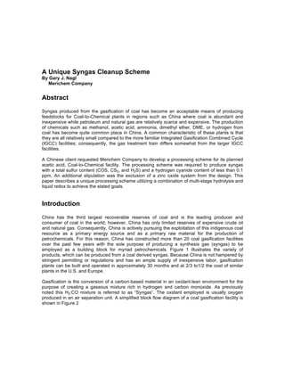
employed as a building block for myriad petrochemicals. Figure 1 illustrates the variety of
products, which can be produced from a coal derived syngas. Because China is not hampered by
stringent permitting or regulations and has an ample supply of inexpensive labor, gasification
plants can be built and operated in approximately 30 months and at 2/3 to1/2 the cost of similar
plants in the U.S. and Europe.
Gasification is the conversion of a carbon-based material in an oxidant-lean environment for the
purpose of creating a gaseous mixture rich in hydrogen and carbon monoxide. As previously
noted this H2:CO mixture is referred to as “Syngas”. The oxidant employed is usually oxygen
produced in an air separation unit. A simplified block flow diagram of a coal gasification facility is
shown in Figure 2
2. Gasifier METHANOL
SYNGAS
CO & H2
Hydrocarbon
Mixed
Alcohols
Oxygen
Steam
EthanolAldehydesAmmonia
Gasoline,
Diesel, etc. MTBE
Formaldehyde
DME
Olefins
Gasoline
Acetic Acid
Vinyl Acetate
Acetic Anhydride
Terephthalic Acid
Figure 1
Coal Derived Chemicals
Air Separation
Unit
Feedstock
Preparation
Steam
GASIFIER
O2
CXHY
ASH/SLAG
SYNGAS
CONDITIONING
COOLING
ASH REMOVAL
WATER GAS SHIFT
SULFUR REMOVAL
CO2 REMOVAL
RAW
SYNGAS
SULFUR
CO2
POWER PLANT
CHEMICALS
CLEAN
SYNGAS
Figure 2
Block Flow Diagram of a Gasification Facility
The overall gasification reaction can be represented as follows:
CxHy + (x/2) O2 xCO +(y/2) H2
The above equation applies to the carbon and hydrogen constituents in a feed stock; however, a
feedstock such as coal has many more constituents, which produce byproducts such as H2S,
HCN, COS, CS2, CO2, Cl2, and ash or slag.
3. CASE STUDY
Merichem Company was approached by a Chinese client who desired to produce acetic acid
from a coal-derived syngas by first producing methanol followed by methanol conversion to acetic
acid as illustrated by the following reactions:
CO + 2H2 CH3OH
CH3 + CO CH3COOH
As can be seen from the above equations, both reactions are equilibrium limited and both require
a catalyst. In addition, both of the catalysts are extremely sensitive to sulfur and hydrogen
cyanide, which is the reason for some unique processing requirements from the client.
In normal applications such as this, the syngas would be treated with an absorption type process
such as amine, which would reduce the overall sulfur content to something less than 10 ppm. The
gas would then be treated in a guard-bed system generally consisting zinc oxide, which would
remove the remaining sulfur compounds. However, the Chinese have had very bad luck with this
approach. Apparently, the absorption processes they employed upstream of the guard beds were
either not capable of or were not operated properly to achieve low levels of sulfur compounds in
the effluent gas resulting in unacceptable change out frequencies of the zinc oxide. Based on this
experience, the client requested that Merichem design a system for treating the gas stream
described in Table 1, which would produce an effluent gas having total sulfur and cyanide
concentrations of less than 0.1 ppm without employing zinc oxide.
Table 1
Raw Syngas Conditions
Flowrate 37,800 Nm3/hr
Pressure 37.0 Bar(g)
Temperature 170
o
C
CO 46.8 %
H2 19.4 %
H2O 20.1 %
CO2 5.4 %
N2 7.8 %
H2S 3,600 ppm
COS 500 ppm
HCN 160 ppm
Total Sulfur 5.1 MTPD
Merichem’s design approach consisted of first cooling the gas stream to remove a large portion of
the water vapor thus reducing the amount of gas to be treated. This would then be followed by
two stages of hydrolysis with intermittent H2S removal via liquid redox. The flow scheme is
illustrated in Figure 3.
CAT
CAT
4. Primary
LO-CAT
Absorber
Polishing
LO-CAT
Absorber
LO-CAT
Oxidizer
Sulfur
Filter
Polishing
Hydrolysis
Reactor
Primary
Hydrolysis
Reactor
SYNGAS
H2O
H2O
Sweet
Syngas
H2O
FLUE GAS
AIR
FILTER CAKE
HEATER
COOLER HEATER
COOLER COOLER
Figure 3
Flow Scheme
The presence of COS, HCN and possibly CS2 prompted the selection of catalytic hydrolysis, to
accomplish the following reactions:
COS + H2O H2S + CO2
CS2 + H2O 2 H2S + CO2
HCN + H2O NH3 + CO
As illustrated, all of the hydrolysis reactions are equilibrium limited, which resulted in the
requirement for a two stage hydrolysis approach. After removal of the water vapor, the H2S
concentration in the syngas feeding the first reactor increases to approximately 4400 ppm, which
subsequently limits the equilibrium conversions of COS and CS2. Consequently, to achieve a very
high overall total sulfur conversion an intermediate H2S removal step had to be incorporated into
the processing scheme. This intermediate H2S removal was then followed by a final hydrolysis
reactor and liquid redox absorber.
H2S REMOVAL
The critical element to the success of the flow scheme illustrated in Figure 3 was the selection of
the H2S removal process. The process had to be commercially proven to be able to achieve very
high H2S removals (>99.9%) at elevated pressures and at favorable economics. In addition, due
to the nature of the upstream gasifier, the process required turndowns approaching 100% for both
flowrate and sulfur loading. To meet these requirements a liquid redox process was selected –
the LOCAT
®
process - due to its long, proven history in similar applications.
The LOCAT process is an ambient temperature, aqueous-based, catalytic (‘Chelated Iron”), redox
process that converts H2S to solid, elemental sulfur. The redox reactions are the oxidation of
sulfide ions (S
=
) to elemental sulfur (S
o
) and the corresponding reduction of ferric ions (Fe
+3
) to
5. ferrous ions (Fe
+2
). Although there are several intermediate steps, the overall process can be
best represented by the direct oxidation of H2S with oxygen as follows:
H2S + ½ O2 H2O + S
o
Since there is a phase change – the formation of solid elemental sulfur – the reaction is not
equilibrium limited; consequently, provided that there are sufficient mass transfer stages to
absorb the required amount of H2S into the aqueous, catalytic solution, very high H2S removal
efficiencies can be achieved. The source of the oxygen is generally air; however, enriched air or
pure oxygen have also been employed. In this application it is imperative that the syngas not be
contaminated with oxygen or nitrogen; consequently, the absorption of the H2S, the formation of
sulfur and the reduction of the ferric ions are accomplished in a separate absorber vessel while
the introduction of air and the oxidation of the ferrous ions back to the active ferric state are
accomplished in a separate oxidizer vessel.
Since the LOCAT process operates at ambient temperature, burners are not required and the
heat content of the sour gas stream is immaterial; consequently, turndown ratios in regards to gas
flow and H2S concentration approach 100%. In addition, since no heat-up is required, the process
can be started up in a matter of hours.
To prevent sulfur accumulation in the system, sulfur is removed on a continuous basis via
filtration by means of gravity, vacuum or pressure filtration, If desired the sulfur can be further
processed in a proprietary melter system to produce molten sulfur suitable for sulfuric acid plants.
As illustrated in Figure 3 there are several wastewater streams produced in the process. The
wastewater streams will contain both dissolved H2S and NH3, which must be removed prior to
discharge. In this case a dual column, sour water stripper system was employed as illustrated in
Figure 4.
Fe
6. Sour Water
Degassing
Vessel
Vent to
LO-CAT
Unit
H2S Stripper
H2S to
LO-CAT Unit
Stripped
Water
NH3 Stripper
NH 3 to
Flare
Stripped
Water
Figure 4
Sour Water Stripper System
In this system the H2S and NH3 are separated into two separate streams. The H2S stream is sent
back to the LOCAT unit for processing while the NH3 is directed to flare.
SUMMARY
Based on a client’s specification for treating a coal-derived syngas to very low levels of total sulfur
and hydrogen cyanide without employing zinc oxide, Merichem designed a unique processing
scheme utilizing a combination of multi-stage hydrolysis and liquid redox to achieve the stated
goals. The secret to success of the system was the liquid redox process – the LOCAT process –
due to its ability to achieve, in an economical manner, H2S removal efficiencies exceeding 99.9%.
The entire facility consisting of a coal gasification unit, syngas clean up facilities and an acetic
acid plant is still the initial startup mode, all indications are that the stated goals will be met.