SlideShare a Scribd company logo
1 of 314
Download to read offline
IPT Portfolio
CM/EH 302-01
Hannah Delp
Table of Contents
Click each internal link to be directed to the document.
Reflection Essay
EH 302 IPT Project Evaluation
Style Guide
Draft 1*
Draft 2*
Draft of Balloon Launch Procedure*
Executive Summary*
Final Draft*
Final Product
* For a description of the edits made to each individual draft, see the comment made at the top of
each first page.
1
Reflection Essay
This essay will serve as a personal reflection of the lessons learned and the tasks completed for
CM/EH 302: Technical Editing, spring 2015.
Learning Over the Course of the Semester
During this class, my partner, Emily Owen, and I learned how to approach a project of this size
with a team of people with different educational backgrounds than we do. Our Integrated Product
Team (IPT), Team F, consisted of several engineering students specializing in aerospace
engineering, computer science, electrical engineering, and mechanical engineering. In addition to
my partner’s background in English and mine in communications, each team member was able
to bring a different set of skills to the table.
Over the semester, I noticed that my communication skills with a large group and with
individuals improved dramatically. This communication included a large quantity of email, text
messages, face-to-face conversations, and addresses to the IPT as a whole. In order to complete
the final report, Emily and I had to spend a great amount of time corresponding with our Project
Manager (PM), Jesse Bracewell, to make sure that we received the drafts from the team members
with enough time for us to edit them. We had to be very clear in our communication with the rest
of the team to make sure that there was no confusion. I also spent a large amount of time
communicating with Emily to come up with a way to divide the work equally between us.
Along with improvements to my communication skills, I have also seen an improvement in my
time management skills. Emily and I also had to be very deliberate with our time, especially
when we were given less time than we expected with the Final Draft. Even though I learned the
2
technical skills that are necessary to be a successful technical editor, I consider what I learned
working with my partner and the rest of the IPT to be equally important.
During the labs, I learned the techniques with Microsoft Word that were necessary for this
project. Many of the techniques, such as combining two different documents, greatly decreased
the amount of time that we spent on each draft. Although I learned many helpful skills in the lab,
Emily and I learned quite a bit through trial and error. When we first attempted to combine both
our edits for Draft 1, the formatting had to be completely redone before we could submit it to our
PM. After learning from this mistake, we began to edit our drafts directly in Word through
Google Drive. For this to work, we had to divide up the work equally so that we would not be
making different edits to the same sections. This worked for Draft 2, but this created a problem
with the Final Draft. While we could edit the same file in Google Drive at different times,
Google Drive would delete any edits that were made while another person was editing the same
document at the same time. Even though we learned this the hard way, I will definitely
remember this the next time that I edit one document with multiple contributors.
Evaluating the Final Product
I am satisfied with the final product that Emily and I submitted to our PM. The final document
was 105 pages long. There were a few mistakes that resulted from combining multiple merged
documents together, but most of these were remedied before we submitted the final report. A
copy of the final submitted report can be found on page 217 of this document.
Emily and I got to work with a wonderful IPT this semester. Our PM did an excellent job
managing the members’ individual tasks and guaranteeing that the completed drafts be turned in
3
to Emily and I a week before they were due. He was always willing to help Emily and I with
whatever task was at hand. As far as I could tell, there were no detrimental conflicts among team
members, and each member completed their individual assignments. Our team even met for
trivia night at Los Trojas Mexican Restaurant and took home first prize. Emily and I could not
have had a better experience.
Working with the Team
As one of the technical editors for Team F, I was responsible for creating a style guide for the
team, editing all documents relating to the final report, and generating a portion of the executive
summary. In order to manage the multiple versions of documents coming from Emily and our
PM, I took charge of version control. This became a great challenge once the document became
too large to email. Because of our trouble with Google Drive, we had to pass around a USB drive
with the document download onto it, edit different portions of the document, add our new files to
the USB drive, and hand the USB drive back to me. At this point, I would merge two documents
together, save the file, and merge the third documents with this merged file. Even though this
process was time consuming, it was the only way to allow multiple contributors to edit a
document simultaneously without trusting it to Google Drive. We were finally able to create a
single document that contained all of the changes that needed to be made to the Final Draft.
Improving as an Editor
As an editor, I need to remind myself that there is only so much that can be done with the
amount of time that I am given. Even though my team was able to get the drafts to Emily and I
with plenty of time to edit them, there was always so much more that could have been done to
improve them. It is an easy rabbit hole to get sucked into, but I have to remind myself of the
4
exercise we did at the beginning of the semester. I have to limit myself to levels of edit that are
appropriate to the assignment.
I also need to train myself to focus on other potential errors other than just those relating to
grammar and spelling. While I am editing, I tend to only look for blatant mechanical errors,
while I look over the subtler errors in completeness of thought and proper citation. I need to set a
goal for what I am editing for before I even look at a document.
Improving the Course
For future semesters, I would recommend that students do research on available version control
software before they begin editing their first drafts. My team spent a lot of time trying to reverse
problems that were caused my either Google Docs or Google Drive. Also, I would recommend
that all students download Google Drive’s program on their own computers. Even though this is
not a perfect way to maintain version control, it can make managing multiple edits on a single
document a little easier.
I would also recommend that technical editors request ALL references that are used in the drafts
before the Final Draft. Editors should ask that links to references be included in all drafts so that
citation placeholders can be added and a reference page can be made beforehand. By the time the
Final Draft was 95 pages long, it took a long time to sift through the pages and insert citations.
As for skills that are learned in class, I do not think that there is anything that could be added that
would help students any further in their projects. Some of the greatest lessons that I learned this
5
semester I learned through making mistakes and having to correct them. Even though these
mistakes were frustrating, they were the best way to learn.
EH 302 IPT Project Evaluation
Complete the following confidential evaluation of yourself and editing partner for
the IPT project.
Name: Hannah Delp
Teamwork Evaluation
How well did you and your editing partner work together? Explain any positive
or negative aspects of your collaboration.
Emily and I worked extremely well together. We never experienced any type
of conflict over the course of the project. I have no negative experiences to
report.
Describe at least one thing you learned about working in groups that will be
useful for you in the future.
Over the course of the semester, I learned how to communicate with the
entire group so that everyone is informed. I also gained a lot of experience
working with a partner on a long-term project that required a lot of
coordination and correspondence. Emily and I had to find ways to divide the
work equally while ensuring that everything was turned in to our team on
time.
Individual Evaluation
List your specific contributions to the IPT project. Explain each contribution.
(Feel free to add numbers)
1. I assisted in the generation of the team’s style guide.
2. I edited my designated portions of Draft 1, Draft 2, and Draft 3.
3. I facilitated the merging of all documents that eventually formed the final report.
4. I introduced Emily Owen and Jesse Bracewell (Team F’s Project Manager) to a function in
Google Drive that allows you to edit and save directly in Word.
5. I maintained version control of the many documents that made up the final report.
Evaluate yourself along the following criteria
Criteria Great Good Adequate Poor
Attendance and participation in IPT meetings X
Effort and work ethic X
Knowledge of editing conventions X
Availability and communication X
What grade would you assign yourself? Provide the grade and a rationale.
Grade: 95
Rationale: I completed all of my assignments on time and attended all of the IPT meetings.
Partner Evaluation
List your partner and explain their contributions to the IPT project (feel free to
add numbers).
Partner’s Name: Emily Owen
Contributions:
1. Emily assisted in the generation of the team’s style guide.
2. Emily edited her designated portions of Draft 1, Draft 2, and Draft 3.
3. Emily checked citations and generated the references page for the final report.
4. Emily generated her designated portion of the executive summary.
5. Emily assisted with the document merge for the final report.
Evaluate your partner along the following criteria
Criteria Great Good Adequate Poor
Attendance and participation in IPT meetings X
Effort and work ethic X
Knowledge of editing conventions X
Availability and communication X
What grade would you assign your partner? Provide the grade and a rationale.
Grade: 100
Rationale: Emily did an excellent job having her deliverables completed on time. She offered plenty
of ideas and feedback while we were creating a schedule. I could not have asked for a better
partner.
1
Style Guide for Post Flight Review Report
IPT Team F
The final report will be edited according to the rules laid out in the Chicago Manual of Style,
16th Edition. The following guide will be helpful for keeping the individual components
consistent with the style of the final report. If you have any questions, please do not hesitate to
contact Emily Owen (owenec@uah.edu) or Hannah Delp (hcd0003@uah.edu). We will revise
the style guide if any problems arise.
Paper Format
Spacing All lines should be 1.5 spaced. Skip one line between
paragraphs and between first order headings and the following
paragraphs. Second order headings will have no space between
the heading and the paragraph.
Example:
Heading 1
Paragraph…
Heading 1
Paragraph…
Margins One inch margins on all sides
Main text font 11 pt. Times New Roman
Page numbers Page numbers go on the bottom right corner of the page; Times
New Roman 11 pt. font
Rules regarding dangling lines Space out the paragraphs so that the last line does not appear on
a different page. Start a new paragraph on the next page if it is
the last line that will fit on a page.
Indentation Do not indent the first line of each paragraph. All lines should
be aligned to the left.
Voice and Word Choice
Passive vs active voice Use the active voice instead of the passive voice. It will sound
stronger, clearer, more direct, and more personal.
Examples:
1. Active voice: Judges must explain the reasons behind
their decisions.
2. Passive voice: The reasons behind their decisions must
be explained by judges.
Pronoun usage Only write in third person (he, she, it, they). Unless you are
being specific, avoid gendered pronouns (they, not he/she).
Contractions Unless you are using a direct quote, avoid any unnecessary
contractions (they will, not they’ll).
2
Headings
Heading format Use simple phrases beginning with a noun (Balloon Launch).
First order heading format Arial, 14 pt. font, blue, bold
Second order heading format Arial, 12 pt. font, black, bold
Heading layout Do not stack headings. When transitioning to Heading 2,
include a brief introduction to Heading 1 (example below).
Heading 1
Brief introduction…………………………
Heading 2
Heading alignment All headings will be aligned to left margin (see example above).
Heading punctuation Do not put any punctuation at the end of headings (see example
above).
Numbers in headings Spell out any numbers that appear in headings (Top Ten).
Heading capitalization Capitalize the first letter of every word in a heading, except for
short, insignificant words like “the”, “and”, or “to”.
Capitalization of headings All words in the heading need to be title case capitalized (Bill of
Materials).
Bulleted Lists
Bullet points All bullet points will be black filled circles
Bulleted items Keep bulleted items brief (1–3 lines long)
Parallel structure If all the items in the bulleted list need to be either complete
sentences or fragments, not a mixture of both. Also, if the first
word in a bulleted item is a verb ending in –ing, then all of the
items in that bulleted list need to be verbs ending in –ing.
Capitalization The first word of a bulleted item is capitalized
Punctuation If the bulleted item is a complete sentence, end it with the
proper end punctuation. If it is a fragment, do not use end
punctuation.
Numbered Lists
Numbering All numbered items will be indicated with an Arabic numeral
followed by a period.
(Refer to Bulleted Lists for
other formatting guidelines)
Punctuation
Serial commas When listing items, use a serial comma (A, B, and C).
En-dash Use an en-dash (a short dash that is the width on the letter “n”)
3
between number ranges (103–108, not 103-108). Word will
automatically generate an en-dash if you type number-space-
hyphen-space-number.
End punctuation Place end punctuation after a set of parentheses at the end of a
sentence, but within quotation marks if the quote comes at the
end of the sentence.
Examples:
1) He yelled, “I don’t think the judge made a fair ruling!”
2) The judge made her ruling (but I don’t think it’s fair).
Symbols Do not use and ampersand (&) in place of “and” (refer to
Numbers for more rules regarding symbols).
Apostrophes When adding an apostrophe to show possession to the end word
that ends in “s”, place the apostrophe at the end of the word and
omit the additional “s” (James’).
Numbers
Numbers in body text Spell out all numbers one through nine. All remaining numbers
can be written numerically.
Numbers in headings (Refer to rules under Headings)
Ordinal numbers Spell out ordinal numbers (first, second, third…) up to tenth.
Do not superscript the letters in remaining ordinal numbers
(34th, not 34th
).
Exceptions Use numerals for measurements, distance, decimal, or a supply
list (3.5 hours, 10 mm, 20˚ Celsius, 5 feet of string, 2 batteries).
Symbols Use the percent symbol (%) rather than spelling out “percent”.
Use a dollar sign ($) to express currency, as long as the amount
includes two decimal places ($1.75). Monetary amounts greater
than or equal to $100 do not need two decimal places ($700).
Monetary amounts over a million can be spelled out ($250
million).
Associated Professors:
Dr. Phillip Farrington
Dr. Matthew Turner
Dr. Michael “P.J.” Benfield
Dr. Cassandra Runyon
Dr. Jon Hakkila
Science Team:
Winslow Dibona- Principal Investigator
Leisha Lopez-Ortiz
Courtney Lawrence
Jenna Snow
Seth Able
Engineering Team:
Jesse Bracewell- Project Manager
Lee Brooks- Chief Engineer
Esra Arnason
Leonard Farr
Bradley Garrison
Laura Langley
Jacob Skaff
Sam Winkler
Technical Editors:
Hannah Delp
Emily Owen
Comment [HD1]:Comment [HD1]:Comment [HD1]:Comment [HD1]: This document (Draft 1)
contains Hannah Delp’s edits only.
Mission Fact Sheet (2 pages)
***TBD***
Table of Contents
A. Science Investigation…………………………………………………………………………..
A.1 Science Background, Goals, and
Objectives…………………………………………...
A.1.1 Goal of sending Sending CubeSat into
atmosphereAtmosphere…………………………………...
A.1.2 Desired
informationInformation……………………………….…………………………
A.2 Science Requirements and Instrumentation……………………………………………
A.2.1 CofC requirements Requirements (Traceability Matrix)
…………………………………...
A.2.2 SMDC
requirementsRequirements……………………………….………………………...
A.2.3 Final Iinstrumentation
usedUsed…………………………………………………...
B. Mission Implementation……………………………….………………………………………
B.1 Mission Concept Solution……………………………….……………………………..
B.1.1 Final design Design of CubeSat (CAD modelModel)
……………………………………...
B.1.2 Concept of
operationsOperations………………………………………………………...
B.2 Mission Requirements and Constraints………………………………………………...
B.2.1 Review CalPoly design Design
requirementsRequirements………………………………………..
B.2.2 Impacts of
requirementsRequirements……………………………….……………………..
B.2.3 Verify that design meets requirementsVerification of Met
Requirements……………………………………………….
B.3 Balloon Launch……………………………….………………………………………..
Formatted:Formatted:Formatted:Formatted: Line spacing: 1.5 lines
B.3.1 Launch
operationsOperations……………………………….…………………………...
B.3.2 Ascent rateRate, descent Descent rate, and burst Burst
altitudeAltitude………………………………….
B.3.3 Trajectory with landing Landing
Ssite…………………………………………………..
B.3.4 Launch recovery Recovery
plansPlans……………………………………………………….
B.4 Data Analysis……………………………….………………………………………….
B.4.1 How data Data will be
analyzedAnalyzed…………………………………………………...
B.4.2 Conclusions from
dataData……………………………….……………………….
B.5 Mission Evaluation and Lessons Learned……………………………………………...
B.5.1 How could Mission couldmission have been
improvedImproved…………………………………….
B.5.2 Problems from
launchLaunch/recoveryRecovery……………………………………………...
B.5.3 Previous/current Current courses Courses
utilizedUtilized…………………………………………….
C. Management……………………………….…………………...……….……………………….
C.1 Team Management Structure…………………………………………………………..
C.1.1 Team member Member roles Roles and
responsibilitiesResponsibilities……………………………………..
C.2 Bill of Materials and Mission Cost…………………………………………………….
C.2.1 Cost of hardware Hardware and
componentsComponents…………………………………………...
C.2.2 Total cost Cost of
missionMission……………………………….………………………...
D. Appendices……………………………….……………………………….……………………
D.1 References……………………………….……………………………….……………
D.2 Team Member Resumes and Concurrence…………………………………………….
D.2.1 Resumes from UAH and COFC
studentsStudents……………………………………
D.3 Data and Supporting Analysis……………………………….…………………………
D.3.1 Raw data Data from
launchLaunch……………………………….……………………….
D.4 Education/Public Outreach……………………………….……………………………
D.4.1 Overview of InSPIRESS……………………………….…………………….
D.4.2 Assigned InSPIRESS team Team
informationInformation…………………………………….
Table of Figures
***TBD***
Table of Symbols
A. Science Investigation
A.1 Science Background, Goals and Objectives (Lee)
A.1.1 Goal of sending CubeSat into atmosphere
A.1.2 Desired information
A.2 Science Requirements and Instrumentation (Esra)
TThe CubeSat has a specification document written by Cal Poly that gives requirements and
constraints that the CubeSat must meet. This specification document gives many general
requirements for CubeSats that will be launched into orbit, however, several of those
requirements and constraints are not applicable to this project and have been waived. The
following items listed are the requirements and constraints that are applicable to this project from
the Cal Poly CubeSat specification: items protruding from the CubeSat must be less than or
equal to 6.5 mm, the total mass of the CubeSat total mass must be less than 2,000 grams, the
CubeSat width and length of a 2U must be 100 plus or minus 0.1 mm, and finally, the CubeSat
height of a 2U must be 227 plus or minus 0.1 mm. These requirements can be seen in the House
of Quality in Figure X.
A.2.1 CofC requirements (Traceability Matrix)
The science team at the College of Charleston (CofC) is a customer that has sent us science goals
that had to me betbe met. They supplied a science traceability that can be found in Table X.A
science traceability was supplied and can be located in Table X. Currently, there are two science
goals with objectives that have been set. The first science goal is to determine the scientific
capabilities of the CubeSat utilizing the Nexus 5 smartphone, while and the first science
objective is to compare the imaging capabilities of the Nexus 5 with an external GoPro. The
second science goal is to test the efficiency of cheap alternatives to pollution monitoring in areas
with production plants, while and the science objective is to perform statistical analysis of air
pollutants in the atmosphere over Decatur, Alabama.
Formatted:Formatted:Formatted:Formatted: Font: (Default) Arial, 14 pt, Bold, Font
color: Accent 1
Formatted:Formatted:Formatted:Formatted: Font: (Default) Arial, Bold
Formatted:Formatted:Formatted:Formatted: Left
Formatted:Formatted:Formatted:Formatted: Font: (Default) Arial
Formatted:Formatted:Formatted:Formatted: Left
Formatted:Formatted:Formatted:Formatted: Font: (Default) Arial, Bold
Formatted:Formatted:Formatted:Formatted: Font: (Default) Arial
Formatted:Formatted:Formatted:Formatted: Left, Line spacing: 1.5 lines
Formatted:Formatted:Formatted:Formatted: Left
Formatted:Formatted:Formatted:Formatted: Left, Line spacing: 1.5 lines
Formatted:Formatted:Formatted:Formatted: Line spacing: 1.5 lines
Formatted:Formatted:Formatted:Formatted: Font: (Default) Arial
Formatted:Formatted:Formatted:Formatted: Left, Line spacing: 1.5 lines
Thee requirements for the first science goal set by the science team at CofC required that are
listed as the following t: The additional camera, GoPro Hero 3+, must be used for comparison.
The Nexus 5 camera is for to capturinge images in the visible spectrum, and the GoPro Hero3+
camera is to capture a is for capturing a video of the entire flight, which will be compared to and
be compared to the camera on the Nexus 5 smartphone.
The requirements forThe the second science goal set by the science team at CofC are listed as the
following:required that measurements be taken, including measurements of atmospheric gasses
and physical atmospheric properties, and the data must be stored in a workable format with
readings in parts per million or parts per billion. a range of atmospheric gases must be measured,
physical atmospheric properties must be measured, and finally the data must be stored in a
workable format with readings in parts per million or parts per billion. Specifically, the
atmospheric gases that are to be measured are the following are: carbon dioxide, carbon
monoxide, nitrogen dioxide, ozone, and sulfur dioxide. These requirements can be seen in the
House of Quality in Figure **X**.
A.2.2 SMDC requirements
A.2.3 Final instrumentation used
The CubeSat used for the final instrumentation was a 2U.
Comment [H2]:Comment [H2]:Comment [H2]:Comment [H2]: Is this sentence necessary?
Formatted:Formatted:Formatted:Formatted: Font: (Default) Arial
Formatted:Formatted:Formatted:Formatted: Indent: Left: 0.5", First line: 0.5"
B. Mission Implementation
To achieve the mission, the payload will use the Nexus 5 smartphone to record images
throughout the flight and gas sensors from alpha sense to record composition of air throughout
the flight. The instrumentations must record and save the data during the flight. In addition, the
instrumentations must survive the mission. To ensure this happens, it is necessary to design a
CubeSat to Cal-Poly specs and print the design using a 3-D printer.
B.1 Mission Concept Solution (Bradley)
To achieve these goals, the CubeSat design had to be large enough to house the major
components of the gas sensor and the Nexus 5, while allowing the instrumentation to reach
outside the CubeSat to gather data. Additionally, the CubeSat had to But also protect the
electronics from exposure to the dynamic thermal effects of the flight, all while. Along with
meeting the FAA regulations while still being cost effective. During flight, the payload could be
exposed to temperatures as low as -60 Celsius. , and Ttypically, most commercial electronics
will shut off at a temperature around 0 Celsius, while industrial electronics will shut off at a
temperature around -40 Celsius.
B.1.1 Final design of CubeSat (CAD model)
To more effectively utilize the three-dimensional3D printers available to the groups, the final
design was a modular design utilizing that utilized a combination of three different part files.
This allowed for easy change and replacement of sections of the CubeSat for alterations in
design, layout, or instrumentation alterations. To solve the temperature issue, the CubeSat was
lined on the inside by a few layers of Mylar to retain the heat radiating from the electronics on
the inside. There are two instruments that require holes for exterior access outside of the
CubeSat. Oone hole is for the gas sensors to collect air sample data, and the other is for the
Nexus 5 lens to capture images during flight. Holes are designed into the location where the
instruments will be housed., Tthe instrumentation is inserted into the holes, and any gaps leading
Formatted:Formatted:Formatted:Formatted: Font: (Default) Arial, 14 pt, Bold, Font
color: Accent 1
Formatted:Formatted:Formatted:Formatted: Line spacing: 1.5 lines
Formatted:Formatted:Formatted:Formatted: Left, Line spacing: 1.5 lines
Formatted:Formatted:Formatted:Formatted: Line spacing: 1.5 lines
Formatted:Formatted:Formatted:Formatted: Font: (Default) Arial, Bold
Formatted:Formatted:Formatted:Formatted: Left
Formatted:Formatted:Formatted:Formatted: Font: (Default) Arial
Formatted:Formatted:Formatted:Formatted: Line spacing: 1.5 lines
Formatted:Formatted:Formatted:Formatted: Left, Line spacing: 1.5 lines
Formatted:Formatted:Formatted:Formatted: Line spacing: 1.5 lines
Formatted:Formatted:Formatted:Formatted: Font: (Default) Arial
Formatted:Formatted:Formatted:Formatted: Line spacing: 1.5 lines
Formatted:Formatted:Formatted:Formatted: Left, Line spacing: 1.5 lines
Comment [H3]:Comment [H3]:Comment [H3]:Comment [H3]: Could you be more specific?
How many layers?
to the inside are sealed to retain heat inside. The structural walls of the CubeSat are designed to
be 10 millimeters mm thick for to provide structural stability of the cube itself and the further
increased heat retention.
B.1.2 Concept of operations (Lee will do picture!)
B.2 Mission Requirements and Constraints (Leonard)
B.2.1 Review CalPoly design requirements
The basic requirements that were set by CalPoly were made in accordance with FCC and FAA
restrictions. The physical restrictions require that the CubeSat be 10 cm x 10 cm x y cm, where y
is either 10, 15, 20, or 30, depending on its type (1U, 1.5U, 2U, and 3U)., The CubeSat and must
also have a mass no greater than 1.33 kg, 2.00 kg, 2.66 kg, or 4.00 kg, respectively. The center of
gravity must be within 2 cm, 3 cm, 4 cm, and 7 cm from its neutral Z-axis, respectively. The -Z-
face of the CubeSat must be the side that gets inserted into the P-POD (Poly Pico satellite Orbital
Deployer) if it is to be launched in this manner. The CubeSat must have nothingnot have
anything protruding on the outside any more than 6.5 mm (deployables are allowed, however,
they must remain encapsulated until allowed to move).
B.2.2 Impacts of requirements
These requirements directly restrict dimensions and total allowable mass, which means that not
only must a product remain in budget, but also it must also perform all of its tasks and still
remain in the physical set of rules. Since this project required the use of a cell phone,
immediately the 1U, with a maximum external dimension of 10 cm, was immediately ruled out.
In order to have all major components fit inside, (, as well as keeping in mind the additional
mass), the 2U was chosen as the CubeSat type. the final verdict on which CubeSat type to use.
B.2.3 Verify that design meets requirements
B.3 Balloon Launch (Laura)
Formatted:Formatted:Formatted:Formatted: Line spacing: 1.5 lines
Formatted:Formatted:Formatted:Formatted: Font: (Default) Arial
Formatted:Formatted:Formatted:Formatted: Font: (Default) Arial, Not Bold
Formatted:Formatted:Formatted:Formatted: Font: (Default) Arial
Formatted:Formatted:Formatted:Formatted: Line spacing: 1.5 lines
Formatted:Formatted:Formatted:Formatted: Font: (Default) Arial, Bold
Formatted:Formatted:Formatted:Formatted: Left
Formatted:Formatted:Formatted:Formatted: Font: (Default) Arial
Formatted:Formatted:Formatted:Formatted: Line spacing: 1.5 lines
Formatted:Formatted:Formatted:Formatted: Font: (Default) Arial
Formatted:Formatted:Formatted:Formatted: Line spacing: 1.5 lines
Formatted:Formatted:Formatted:Formatted: Left, Line spacing: 1.5 lines
Formatted:Formatted:Formatted:Formatted: Line spacing: 1.5 lines
Formatted:Formatted:Formatted:Formatted: Font: (Default) Arial
Formatted:Formatted:Formatted:Formatted: Line spacing: 1.5 lines
Formatted:Formatted:Formatted:Formatted: Left, Line spacing: 1.5 lines
Formatted:Formatted:Formatted:Formatted: Line spacing: 1.5 lines
Formatted:Formatted:Formatted:Formatted: Font: (Default) Arial
Formatted:Formatted:Formatted:Formatted: Line spacing: 1.5 lines
Formatted:Formatted:Formatted:Formatted: Font: (Default) Arial, Bold
Formatted:Formatted:Formatted:Formatted: Left
Formatted:Formatted:Formatted:Formatted: Font: (Default) Arial
B.3.1 Launch operations
The launch operations are set up into three main sections. The first is preparation. Adequate
preparation is an essential part of a successful launch in thatbecause it allows for a much
smoother process. Before the day of the launch, many things steps need to be completed. The
SPOT tracker, GoPros, and all other technical equipment should be tested. Also, the parachute
should already be attached to twenty feet of cord on each side and rolled up. Strings used for
tying the balloon neck should also be precut.
The second part step of launch operations is filling the balloon. This process involves the
balloon, helium, connecting hose, hose clamp, precut string loop, fish scale, and another piece of
precut string. Once the hose is attached to the helium, the loop and clamp are placed on the hose.
At this point, the hose is inserted into the balloon and the helium is turned on. The balloon will
continue to fill up with helium until it has reached the desired lift. The lift can be determined by
using the fish scale. Once the desired lift is reached, the top of the neck of the balloon is tied off
with string, and the balloon is removed from the hose.
The final part step of the launch operations is to tie off the balloon and launch. At this point in
the procedure, an individual should be holding the balloon just above where the first string was
tied. Another tie will then need to be added at the bottom of the balloon neck. The neck will then
be folded in half, with the loop in between the ties, and taped together. This will allow someone
to hold the balloon by the loop. Once the balloon is tied off completely, the only remaining steps
are to attach the payload, turn on the electronics, and launch the balloon.
B.3.2 Ascent rate, descent rate, and burst altitude
B.3.3 Trajectory with landing site
B.3.4 Launch recovery plans
Formatted:Formatted:Formatted:Formatted: Line spacing: 1.5 lines
Formatted:Formatted:Formatted:Formatted: Font: (Default) Arial
Formatted:Formatted:Formatted:Formatted: Line spacing: 1.5 lines
Formatted:Formatted:Formatted:Formatted: Left, Line spacing: 1.5 lines
Formatted:Formatted:Formatted:Formatted: Line spacing: 1.5 lines
Formatted:Formatted:Formatted:Formatted: Left, Line spacing: 1.5 lines
Formatted:Formatted:Formatted:Formatted: Line spacing: 1.5 lines
Formatted:Formatted:Formatted:Formatted: Font: (Default) Arial
Formatted:Formatted:Formatted:Formatted: Indent: Left: 0.5", First line: 0.5"
B.4 Data Analysis (Jacob)
B.4.1 How data will be analyzed
The launching of theLaunching the CubeSat provides an opportunity for data acquisition. The
specific types of data that is will be acquired and recorded during launch are the altitude of the
CubeSat, the pressures and temperatures at these specific altitudes, and the concentrations of
sulfur dioxide, nitrogen dioxide, carbon monoxide, and ozone gases. Each of the recorded values
can be traced to specific time and altitude during flight.
The Ttwo different sets of instrumentations are used to gather altitude, temperature, and pressure.
These instrumentations are the Nexus 5 smart phone, which utilizeszing the AndroSensor
application, and the flight computer. The AndroSensor application is capable of running in the
background of the Nexus 5 and obtaining 7 seven different categories of data. These categories
are location, accelerometeracceleration, light, magnetic field, orientation, proximity, and battery
status. The location is defined by values of latitude/ and longitude, and altitude. Only two of
these categories, (location and accelerometeracceleration), are relevant for data analysis. The
numbers associated with latitude and longitude pinpoint the exact location of the CubeSat as it
travels, depicting the path taken during flight. The values of altitude represent the height at a
given latitude and/ longitude the CubeSat reaches. In combinationCombined, these three values
allow the location of the CubeSat to be determined at any moment during flight. The
accelerometer data shows the “g- forces” achieved in each axial direction, thus, showing the
acceleration in the x, y, and z directions at any time during flight. The flight computer also
measures latitude/longitude and altitude, in addition to, pressure and temperature. The pressure
readings are equivalent to the amount of force being applied perpendicularly to the surface of the
flight computer per unit area. The temperature values are equal to the temperature of the
atmosphere at a given time. These values of pressure and temperature are unique to a specific
height in the atmosphere.
Formatted:Formatted:Formatted:Formatted: Line spacing: 1.5 lines
Formatted:Formatted:Formatted:Formatted: Font: (Default) Arial, Bold
Formatted:Formatted:Formatted:Formatted: Left
Formatted:Formatted:Formatted:Formatted: Font: (Default) Arial
Formatted:Formatted:Formatted:Formatted: Line spacing: 1.5 lines
Formatted:Formatted:Formatted:Formatted: Font: (Default) Arial
Formatted:Formatted:Formatted:Formatted: Line spacing: 1.5 lines
Formatted:Formatted:Formatted:Formatted: Left, Line spacing: 1.5 lines
Four different gas sensors, purchased from AlphaSense, are also utilized for data acquisition.
These sensors are the CO-A4, SO2-A4. O3-A4, and NO2-A4. Each sensor measures gas
concentration by recording a voltage output. **NOT FINISHED**
B.4.2 Conclusions from data
B.5 Mission Evaluation and Lessons Learned (Sam)
B.5.1 How could mission have been improved
B.5.2 Problems from launch/recovery
B.5.3 Previous/current courses utilized
C. Management (Jesse) ***Not finished***
C.1 Team Management Structure (Jesse)
Dr. Robert A. Altenkirch, UAH President
Formatted:Formatted:Formatted:Formatted: Line spacing: 1.5 lines
Formatted:Formatted:Formatted:Formatted: Font: (Default) Arial
Formatted:Formatted:Formatted:Formatted: Line spacing: 1.5 lines
Formatted:Formatted:Formatted:Formatted: Font: (Default) Arial, Bold
Formatted:Formatted:Formatted:Formatted: Left
Formatted:Formatted:Formatted:Formatted: Font: (Default) Arial
Formatted:Formatted:Formatted:Formatted: Line spacing: 1.5 lines
Formatted:Formatted:Formatted:Formatted: Font: (Default) Arial
Formatted:Formatted:Formatted:Formatted: Indent: Left: 0.5", First line: 0.5", Line
spacing: 1.5 lines
Formatted:Formatted:Formatted:Formatted: Line spacing: 1.5 lines
Formatted:Formatted:Formatted:Formatted: Indent: Left: 0.5", First line: 0.5", Line
spacing: 1.5 lines
Formatted:Formatted:Formatted:Formatted: Line spacing: 1.5 lines
Dr. Christine Curtis, UAH Provost
Dr. Shankar Mahalingam, UAH Dean of Engineering
Dr. Paul D. Collopy, Department Chair ISE
Dr. Keith Hollingsworth, Department Chair MAE
Dr. Phillip Farrington, Professor
Dr. Matthew Turner, Professor
Dr. Michael P.J. Benfield
Jesse Bracewell, Project Manager
Lee Brooks, Chief Engineer
Esra Arnason, Supporting Engineer
Hannah Delp, Technical Editor
Leonard Farr, Supporting Engineer
Bradley Garrison, Supporting Engineer
Laura Langley, Supporting Engineer
Emily Owen, Technical Editor
Jacob Skaff, Supporting Engineer
Samuel Winkler, Supporting Engineer
Winslow DiBona, Principal Investigator
Leisha Lopez-Ortiz, Co-Principal Investigator
Seth Able, Co-Investigator
Courtney Lawrence, Co-Investigator
Jenna Snow, Co-Investigator
C.1.1 Team member roles and responsibilities
Jesse Bracewell, Project Manager
Lee Brooks, Chief Engineer
Esra Arnason, Requirements & CubeSat Construction
Hannah Delp, Technical Editor
Leonard Farr, CubeSat Design & Testing
Bradley Garrison, CAD & CubeSat Design
Laura Langley, CubeSat Design & Smartphone Image Components
Emily Owen, Technical Editor
Jacob Skaff, Sensor Design & Testing
Samuel Winkler, Sensor Design & Testing
C.2 Bill of Materials and Mission Cost (Jesse)
C.2.1 Cost of hardware and components
Formatted:Formatted:Formatted:Formatted: Font: (Default) Arial, Bold
C.2.2 Total cost of mission
D. Appendices
D.1 References
D.2 Team Member Resumes and Concurrence
D.2.1 Resumes from UAH and COFC students
D.3 Data and Supporting Analysis
D.3.1 Insulation test report
D.3.2 Raw data from launch
D.4 Education/Public Outreach
D.4.1 Overview of InSPIRESS
D.4.2 Assigned InSPIRESS team information
Appendix D.3.1: CubeSat Insulation Test Report
Abstract
In order to keep the electronic components functioning while in high-altitude temperatures,
insulation must be implemented to keep the heat trapped inside for as long as possible. The only
two sources of insulation that was immediately available were regular insulation foam and a
sheet of Mylar. The purpose of the test was to see which of the two insulation mediums would be
more efficient in decreasing heat loss. A specially designed CubeSat was 3-D printed that
hadwith two separate compartments, one with Mylar and the other with insulation foam. The
final test haFor the final test,d two similar flight computers were placed in each compartment
with identical thermocouple sensors., and Tthe entire test article was placed inside a Yeti cooler
with a broken- down piece of dry ice in order to expose the CubeSat to temperatures that are
found in at high -altitude. The final result had showed the Mylar insulation decreasing in
temperature in a decreasing slope, and thusly, slowly decreasing the loss of heat as time
increases. These tests that of useding dry ice were more economical and efficient when testing
for insulation efficiency rather than launching high-altitude balloons and retrieving the balloons
hours after launch.
Objective
The objective was to get a quick result regarding which form of insulation was better, not the
best. Although these results are very similar, the Mylar insulation was slightly more effective
than the foam insulation. The final results of the insulation show that the Mylar had a decreasing
slope, meaning its temperature loss decelerates compared to the foam.
Testing Procedure
Rather than launching the CubeSat with the high altitude balloons and then retrieving them, it
was determined that ground- level, deep-freezing tests would be more economical and efficient
since results were needed immediately. To determine real-time results, the variable of different
starting temperatures and measurements was removed by using two identical measuring devices
Formatted:Formatted:Formatted:Formatted: Font: (Default) Arial, 14 pt, Bold, Font
color: Accent 1
Formatted:Formatted:Formatted:Formatted: Font: (Default) Arial
Formatted:Formatted:Formatted:Formatted: Left, Line spacing: 1.5 lines
Comment [H4]:Comment [H4]:Comment [H4]:Comment [H4]: Consider rewording
Formatted:Formatted:Formatted:Formatted: Font: (Default) Arial
Formatted:Formatted:Formatted:Formatted: Left, Line spacing: 1.5 lines
Formatted:Formatted:Formatted:Formatted: Font: (Default) Arial
Formatted:Formatted:Formatted:Formatted: Left, Line spacing: 1.5 lines
(thermocouples with flight computers that each group was given), which were activated and at
the exact same time and placed into the cooler simultaneously as well.
Figure 1: The dry ice maxed beyond -76 °F which means that it was much cooler than the
targeted temperature. The actual temperature could not be determined but it was below natural
high-altitude temperatures.
The picture above (Figure 1) was a thermal image taken of the dry ice to confirm the temperature
zone. The Flir One thermal camera maxed out at -76 ° F.
Figure 2: The CubeSat had two compartments: empty compartment with Mylar, and another
compartment filled with foam and an internal tub (orange plastic print) to give heat resistance to
the outside environment.
The test that was performed on Feb. February 10 was redone on FebFebruary 12 because the data
was not reliable since there were too many variables. The earlier tests made use of a single flight
computer, which was placed in both compartments at different times. This meant that the
Formatted:Formatted:Formatted:Formatted: Left, Line spacing: Double
Formatted:Formatted:Formatted:Formatted: Left, Line spacing: 1.5 lines
temperature readings and the overall temperature of the CubeSat had too many variables. The
temperature could have started already pre-chilled, despite the amount of time between tests
while that the test article warmed up in room temperature. Figure 3 shows the earlier test setup
(with an Arduino rather than a second flight computer).
Figure 3: The flight computer was placed inside the foam section (covered with Styrofoam)
Figure 4: Since the earlier tests had too many variables, they served more as a proof of concept.
These images above (Figure 4) show the temperature readings of both compartments (with the
Styrofoam cover removed). The left side was the foam side; the right side was the Mylar.
The Mylar was very reflective, and although the reflection of light also makes a reflection of
infrared radiation, these images were taken at night with minimal lighting (all warm signatures
are actual heat signatures and not reflections).
Comment [H5]:Comment [H5]:Comment [H5]:Comment [H5]: Consider rewording.
Formatted:Formatted:Formatted:Formatted: Left
Formatted:Formatted:Formatted:Formatted: Left, Line spacing: 1.5 lines
Figure 5: The CubeSat after thirty minutes of <-76°F temperatures
Results
These tests were performed under the assumptions that the CubeSat will warm back up as it
enters high altitude via infrared radiation and that the amount of time it spends in cold
temperatures is approximately thirty minutes. This test also answered the question of how the
device would behave if no heating source were added in (design constraints, weight, etc.). The
arduino was powered after the tests in order to see if the electronics of a bare circuit board would
still function after being exposed to cold temperatures, which resulted in with positive results.
The temperatures did not have direct dry ice exposure since there was an equal gap of air around
the surface area of the CubeSat. Both flight computers were activated at the same time.
Formatted:Formatted:Formatted:Formatted: Left, Line spacing: 1.5 lines
Comment [H6]:Comment [H6]:Comment [H6]:Comment [H6]: Consider rewording.
Figures 5 and 6: These graphs show the data that both flight computers collected
simultaneously. The slopes were observed more than the temperature vs. time. These graphs
show that as time progresses, the temperature loss inside the Mylar decreased over time, whereas
the foam continuously decreased without leveling out.
Formatted:Formatted:Formatted:Formatted: Left
Formatted:Formatted:Formatted:Formatted: Font: Bold
D.4 Education/Public Outreach
D.4.1 Overview of InSPIRESS
D.4.2 Assigned InSPIRESS team information
Associated Professors:
Dr. Phillip Farrington
Dr. Matthew Turner
Dr. Michael “P.J.” Benfield
Dr. Cassandra Runyon
Dr. Jon Hakkila
Science Team:
Winslow Dibona- Principal Investigator
Leisha Lopez-Ortiz
Courtney Lawrence
Jenna Snow
Seth Able
PPOOSSTT FFLLIIGGHHTT RREEVVIIEEWW
AAPPRRIILL 2233,, 22001155
Engineering Team:
Jesse Bracewell- Project Manager
Lee Brooks- Chief Engineer
Esra Arnason
Leonard Farr
Bradley Garrison
Laura Langley
Jacob Skaff
Sam Winkler
Technical Editors:
Hannah Delp
Emily Owen
Comment [HD1]:Comment [HD1]:Comment [HD1]:Comment [HD1]: This document (Draft 2)
contains Hannah Delp’s edits only
StyleStyleStyleStyle Definition:Definition:Definition:Definition: Heading 3: Font: Not Bold, Indent:
Left: 1"
StyleStyleStyleStyle Definition:Definition:Definition:Definition: Heading 1: Font: Bold
Formatted:Formatted:Formatted:Formatted: Font: 18 pt
Mission Fact Sheet (2 pages)
***TBD***
Table of Contents
A. Science
Investigation………………………………………………………………………………………...
A.1 Science Background, Goals, and Objectives…………………………………………..
A.1.1 Sending CubeSat into Atmosphere…………………………………………..
A.1.2 Desired Information……………………………….………………………....
A.2 Science Requirements and Instrumentation……………………………………………
A.2.1 CofC Requirements (Traceability Matrix) …………………………………..
A.2.2 SMDC Requirements……………………………….………………………..
A.2.3 Final Instrumentation Used…………………………………………………..
B. Mission Implementation……………………………….………………………………………
B.1 Mission Concept Solution……………………………….……………………………..
B.1.1 Final Design of CubeSat (CAD Model) ……………………………………..
B.1.2 Concept of Operations………………………………………………………..
B.2 Mission Requirements and Constraints………………………………………………...
B.2.1 Review of CalPolyCal Poly Design
Requirements……………………………………
B.2.2 Impacts of Requirements……………………………….…………………….
B.2.3 Verification of Met Requirements……………………………………………
B.3 Balloon Launch……………………………….………………………………………..
B.3.1 Launch Operations…………………………………………………………...
B.3.2 Ascent Rate, Descent Rate, Descent Date, and Burst Altitude………………
B.3.3 Trajectory with Landing Site…………………………………………………
B.3.4 Launch Recovery Plans ……………………………………………………...
B.4 Data Analysis……………………………….………………………………………….
B.4.1 How Data will be Analyzed………………………………………………….
B.4.2 Conclusions from Data……………………………….………………………
B.5 Mission Evaluation and Lessons Learned……………………………………………...
B.5.1 How Mission could have been Improved…………………………………….
B.5.2 Problems from Launch/Recovery…………………………………………….
B.5.3 Previous/Current Courses ……………………………………………………
C. Management……………………………….…………………...……….……………………….
C.1 Team Management Structure…………………………………………………………..
C.1.1 Team Member Roles and Responsibilities…………………………………...
C.2 Bill of Materials and Mission Cost…………………………………………………….
C.2.1 Cost of Hardware and Components………………………………………….
C.2.2 Total Cost of Mission……………………………….………………………..
D. Appendices……………………………….……………………………….……………………
D.1 References……………………………….……………………………….……………
D.2 Team Member Resumes and Concurrence…………………………………………….
D.2.1 Resumes from UAH and COFC Students……………………………………
D.3 Data and Supporting Analysis……………………………….…………………………
D.3.1 Raw Data from Launch……………………………….……………………
D.4 Education/Public Outreach……………………………….……………………………
D.4.1 Overview of InSPIRESS……………………………….…………………….
D.4.2 Assigned InSPIRESS Team Information…………………………………….
Table of Figures
***TBD***
Table of Symbols
A. Science Investigation
A.1 Science Background, Goals and Objectives (Lee)
A.1.1 Goal of sending Sending CubeSat into atmosphereAtmosphere
A.1.2 Desired informationInformation
A.2 Science Requirements and Instrumentation (Esra)
The CubeSat has a specification document written by Cal Poly that gives requirements and constraints
that the CubeSat must meet. This specification document gives many general requirements for CubeSats
that will be launched into orbit., howeverHowever, several of those requirements and constraints are not
applicable to this project and have been waived. The following items listed are the requirements and
constraints that are applicable to this project from the Cal Poly CubeSat specification: items protruding
from the CubeSat must be less than or equal to 6.5 mm, the total mass of the CubeSat must be less than
2,000 grams, the CubeSat width and length of a 2U must be 100 plus or minus 0.1 mm, and finally, the
CubeSat height of a 2U must be 227 plus or minus 0.1 mm. These requirements can be seen in the House
of Quality in Figure X.
A.2.1 CofC requirements Requirements (Traceability Matrix)
The science team at the College of Charleston (CofC) is a customer that has sent us science goals that had
to be met. They supplied a science traceability that can be found in Table X. Currently, there are two
science goals with objectives that have been set. The first science goal is to determine the scientific
capabilities of the CubeSat utilizing the Nexus 5 smartphone, and the first science objective is to compare
the imaging capabilities of the Nexus 5 with an external GoPro. The second science goal is to test the
efficiency of cheap alternatives to pollution monitoring in areas with production plants, and the second
science objective is to perform a statistical analysis of air pollutants in the atmosphere over Decatur,
Alabama.
Formatted:Formatted:Formatted:Formatted: Heading 1, Line spacing: single
Formatted:Formatted:Formatted:Formatted: Heading 2, Indent: Left: 0", Line
spacing: single
Formatted:Formatted:Formatted:Formatted: Heading 3, Indent: Left: 0", Line
spacing: single
Formatted:Formatted:Formatted:Formatted: Heading 3, Indent: Left: 0", Line
spacing: single
Formatted:Formatted:Formatted:Formatted: Heading 2, Indent: Left: 0", Line
spacing: single
Formatted:Formatted:Formatted:Formatted: Left
Formatted:Formatted:Formatted:Formatted: Heading 3, Indent: Left: 0", Line
spacing: single
Formatted:Formatted:Formatted:Formatted: Left
The first science goal set by the science team at CofC required that an additional camera, specifically a
GoPro Hero 3+, be used for comparison. The Nexus 5 camera will capture images in the visible spectrum,
and the GoPro Hero3+ camera is for capturing a video of the entire flight, which will be compared to the
camera on the Nexus 5 smartphone.
The second science goal set by the science team at CofC required that measurements be taken, including
measurements of atmospheric gasses and physical atmospheric properties, and the data must be stored in a
workable format with readings in parts per million or parts per billion. Specifically, the atmospheric gases
that are to be measured are carbon dioxide, carbon monoxide, nitrogen dioxide, ozone, and sulfur dioxide.
These requirements can be seen in the House of Quality in Figure **X**.
A.2.2 SMDC Rrequirements
SMDC is funding the project and has set the baseline mission, which is to build a CubeSat utilizing the
Nexus 5 smartphone. Additional requirements set by SMDC include the following:
• exploiting Exploiting the Nexus 5 smartphone capabilities (specifically the smartphone’s camera)
and integrating these technologies into the CubeSat,
• Rremaining within a budget of $5,000,
• Ensuring that the payload’s weight remains under 12 pounds according to FAA regulation (follow
FAA weight requirements of less than 12 pounds (DIY Space Exploration),
• Mmeeting the additional science goals set by CofC,
• Llaunching the balloon on a high altitude weather balloon,
• Ensuring that the CubeSat is durable enough to must survivesurvive the mission and be durable,
and finally the
• Recovering and analyzing and CubeSat’s data after the balloon launch.
with all of the data that is to be analyzed must be recovered after the balloon launch. These requirements
can be seen in the House of Quality in Figure **X**
A.2.3 Final instrumentation usedUsed
Formatted:Formatted:Formatted:Formatted: Left
Formatted:Formatted:Formatted:Formatted: Heading 3, Indent: Left: 0", Line
spacing: single
Formatted:Formatted:Formatted:Formatted: Left
Formatted:Formatted:Formatted:Formatted: Left, Bulleted + Level: 1 + Aligned at:
0.25" + Indent at: 0.5"
Formatted:Formatted:Formatted:Formatted: Font:
Comment [HD2]:Comment [HD2]:Comment [HD2]:Comment [HD2]: Is this a citation?
Formatted:Formatted:Formatted:Formatted: Font:
Comment [HD3]:Comment [HD3]:Comment [HD3]:Comment [HD3]: Did you mean “CubeSat”?
Consider replacing.
Formatted:Formatted:Formatted:Formatted: Font:
Formatted:Formatted:Formatted:Formatted: Left, Indent: Left: 0.5"
Formatted:Formatted:Formatted:Formatted: Left, Indent: Left: 0", Hanging: 0.5"
Formatted:Formatted:Formatted:Formatted: Heading 3, Indent: Left: 0", Line
spacing: single
For the final instrumentationA a 2U CubeSat was used in the launch for the final instrumentation. The
Cube met all size and weight requirements given by CalPolyCal Poly. One of the science goals from
CofC required that was to use a GoPro be used to and take a video of the entire flight and to compare to
the images taken on the Nexus 5 smartphone. A GoPro Hero 3+ was used for the final instrumentation
and the Nexus 5 was utilized to taketook pictures continuously throughout the flight.
For the second science goal, 4 four sensors were purchased to measure specific gas components in the
atmosphere. The sensors were all connected to an Arduino board to store the data measured during the
flight.
B. Mission Implementation
To achieve the mission, the payload will record images throughout the flight usinge the Nexus 5
smartphone to record images throughout the flight and record air composition throughout the flight using
gas sensors from alpha sense. to record composition of air throughout the flight. The instruments must
record and save the data during the flight. In addition, the instruments must survive the mission. To
ensure this happens, it is necessary to design a CubeSat to Cal-Poly specs and print the design using a 3D
printer.
B.1 Mission Concept Solution (Bradley)
To achieve these goals, the CubeSat design had to be large enough to house the major components of the
gas sensor and the Nexus 5 while allowing the instruments to reach outside the CubeSat to gather data.
Additionally, the CubeSat had to protect the electronics from exposure to the dynamic thermal effects of
the flight, all while meeting the FAA regulations while still being cost effective. During the flight, the
payload could be exposed to temperatures as low as -60˚ Celsius. Typically, most commercial electronics
will shut off at a temperature around 0˚ Celsius, while industrial electronics will shut off at a temperature
around -40 Celsius.
B.1.1 Final design of CubeSat (CAD model)
Formatted:Formatted:Formatted:Formatted: Left
Formatted:Formatted:Formatted:Formatted: Heading 1, Line spacing: single
Formatted:Formatted:Formatted:Formatted: Left
Formatted:Formatted:Formatted:Formatted: Heading 2, Indent: Left: 0", Line
spacing: single
Formatted:Formatted:Formatted:Formatted: Left
Formatted:Formatted:Formatted:Formatted: Heading 3, Indent: Left: 0", Line
spacing: single
To more effectively utilize the 3D printers available to the groups, the final design was a modular design
that utilized a combination of three different part files. This allowed for easy change and replacement of
sections of the CubeSat for design, layout, or instrument alterations. To solve the temperature issue, the
CubeSat was lined on the inside by with layers of Mylar to retain the heat radiating from the electronics
on the inside. There are two instruments that require holes for access outside of the CubeSat. One hole is
for the gas sensors to collect air sample data, and the other hole is for the Nexus 5 lens to capture images
during flight. The holes are designed into the location where the instruments will be housed. The
instrumentation is inserted into the holes, and any gaps leading to the inside are sealed to retain heat. The
structural walls of the CubeSat are designed to be 10 mm thick to provide structural stability and
increased heat retention.
B.1.2 Concept of operations Operations (Lee will do picture!)
B.2 Mission Requirements and Constraints (Leonard)
B.2.1 Review of the CalPolyCal Poly design Design
requirementsRequirements
The basic requirements that were set by CalPolyCal Poly were made in accordance with FCC and FAA
restrictions. The physical restrictions require that the CubeSat be 10 cm x 10 cm x y cm, where y is 10,
15, 20, or 30, depending on its type (1U, 1.5U, 2U, and 3U). The CubeSat must also have a mass no
greater than 1.33 kg, 2.00 kg, 2.66 kg, or 4.00 kg, respective to the body type. The center of gravity must
be within 2 cm, 3 cm, 4 cm, and 7 cm from its neutral Z-axis. The Z-face of the CubeSat must be the side
that gets inserted into the P-POD (Poly Pico satellite Orbital Deployer) if it is to be launched in this
manner. The CubeSat must not have anything protruding on the outside any more than 6.5 mm
(deployables are allowed, however, they must remain encapsulated until allowed to move).
B.2.2 Impacts of the Rrequirements
These requirements directly restrict dimensions and total allowable mass, which means that not only must
a product remain in budget, but it must also perform all of its tasks and still remain in the physical set of
rules. Since this project required the use of a cell phone, the 1U , with a( maximum external dimension
Formatted:Formatted:Formatted:Formatted: Left
Formatted:Formatted:Formatted:Formatted: Heading 3, Indent: Left: 0", Line
spacing: single
Formatted:Formatted:Formatted:Formatted: Heading 2, Indent: Left: 0", Line
spacing: single
Formatted:Formatted:Formatted:Formatted: Heading 3, Indent: Left: 0", Line
spacing: single
Formatted:Formatted:Formatted:Formatted: Left
Formatted:Formatted:Formatted:Formatted: Heading 3, Indent: Left: 0", Line
spacing: single
Formatted:Formatted:Formatted:Formatted: Left
equaling of 10 cm), was immediately ruled out. In order to have all major components fit inside, (keeping
in mind the additional mass) the 2U was chosen as the CubeSat type. This decision also enables what all
internal components may be added, not only for physical constraints but ease of access and necessary
corrections.
B.2.3 Verification of Met Design Requirements
Verify that design meets requirements
The first requirement, regarding the physical dimensions, was met by designing the outer 3-D printed
shell to fit within the specified parameters. The second requirement, regarding the total mass of the
system, was calculated to fall within the 2.00 kg limit by tabulating and adding up all the weights of each
component, as well as the printed CubeSat itself. Finally, the third requirement, regarding the center of
mass, requirement was satisfied by distributing equal weight from each component to key locations in
order to balance out the device.
B.3 Balloon Launch (Laura)
B.3.1 Launch operationsOperations
The launch operations are set up into three main sections. The first is preparation. Adequate preparation is
an essential part of a successful launch because it allows for a much smoother launch process. Before the
day of the launch, many steps need to be completed. The SPOT tracker, GoPros, and all other technical
equipment should be tested. Also, the parachute should already be attached to twenty feet of cord on each
side and rolled up. Strings used for tying the balloon neck should also be precut.
The second step of launch operations is filling to fill the balloon. This process involves the balloon,
helium, connecting hose, hose clamp, precut string loop, fish scale, and another piece of precut string.
Once the hose is attached to the helium, the loop and clamp are placed on the hose. At this point, the hose
is inserted into the balloon and the helium is turned on. The balloon will continue to fill up with helium
until it has reached the desired lift. The lift can be determined by using the fish scale. Once the desired lift
Comment [HD4]:Comment [HD4]:Comment [HD4]:Comment [HD4]: I'm not sure what this
sentence means. Consider revising.
Formatted:Formatted:Formatted:Formatted: Heading 3, Line spacing: single
Formatted:Formatted:Formatted:Formatted: Heading 3, Indent: Left: 0", Line
spacing: single
Formatted:Formatted:Formatted:Formatted: Heading 3, Line spacing: single
Formatted:Formatted:Formatted:Formatted: Left
Formatted:Formatted:Formatted:Formatted: Heading 2, Indent: Left: 0", Line
spacing: single
Formatted:Formatted:Formatted:Formatted: Heading 3, Line spacing: single
Formatted:Formatted:Formatted:Formatted: Heading 3, Indent: Left: 0", Line
spacing: single
Formatted:Formatted:Formatted:Formatted: Left
is reached, the top of the neck of the balloon is tied closed off with string and the balloon is removed from
the hose.
The final step of the launch operations is to tieis to tie off the balloon neck and launch the balloonlaunch.
At this point in the procedure, an individual should be holding the balloon just above where the first string
was tied. Another tie will then be added at the bottom of the balloon neck. The neck will then be folded in
half, with the loop in between the ties, and taped together. This will allow someone to hold the balloon by
the loop. Once the balloon is tied off completely, the only remaining steps are to attach the payload, turn
on the electronics, and launch the balloon.
B.3.2 Ascent rateRate, descent Descent rateRate, and burst Burst
altitudeAltitude
A series of models are used to predict the rate that the payload will ascend, the altitude it will burst, and
the rate is it will descend after is bursts. The first model used is the burst altitude model. The inputs for
this model are the payload weight and the balloon lift. When entered into the spreadsheet, the ascent rate
and the burst altitude are calculated. The second model used is the descent model. The inputs for this
model are the payload mass and the diameter of the attached parachute. Once those values are put into the
model, it will then calculate the descent rate of the payload after the balloon bursts.
B.3.3 Trajectory with landing Landing siteSite
The trajectory of the payload after the balloon bursts and the landing location are calculated using
software found on the HabHub website cite. The inputs for this software are the latitude and longitude of
the launch location, launch altitude, launch time, launch date, ascent rate, burst altitude, and descent rate.
Once those parameters are entered, the software will show the predicted trajectory along with the landing
site. The landing site is usually accurate within a mile or two.
B.3.4 Launch recovery Recovery plansPlans
Due to the fact that payload retrievals have been difficult in the past, two days are being set aside for the
recovery. Also, the recovery team will consist of three team members (at the very minimum). Gear worn
Formatted:Formatted:Formatted:Formatted: Left
Formatted:Formatted:Formatted:Formatted: Heading 3, Indent: Left: 0", Line
spacing: single
Formatted:Formatted:Formatted:Formatted: Left
Formatted:Formatted:Formatted:Formatted: Heading 3, Indent: Left: 0", Line
spacing: single
Formatted:Formatted:Formatted:Formatted: Left
Formatted:Formatted:Formatted:Formatted: Heading 3, Indent: Left: 0", Line
spacing: single
Formatted:Formatted:Formatted:Formatted: Left
by the team will consist of hiking boots and clothes suited for walking through the woods. The team will
also bring other gear used to retrieve the payload, such as hatchets, a gpsGPS, a chainsaw, and the
recovery kit provided by the professors.
B.4 Data Analysis (Jacob)
B.4.1 How the data Data will will be analyzedAnalyzed
Launching the CubeSat provides an opportunity for data acquisition. The specific types of data that will
be acquired and recorded during launch are the altitude of the CubeSat, the pressures and temperatures at
these specific altitudes, and the concentrations of sulfur dioxide, nitrogen dioxide, carbon monoxide, and
ozone gases in the atmosphere. Each of the recorded values can be traced to specific times and altitudes
during flight. Two different sets of instruments will be. are used to gather altitude, temperature, and
pressure. These instruments are the Nexus 5 smart phone, which utilizes the AndroSensor application, and
the flight computer. The AndroSensor application is capable of running in the background of the Nexus 5
and obtaining seven different categories of data. These categories are location, acceleration, light,
magnetic field, orientation, proximity, and battery status.
The location is defined by values of latitude/longitude and altitude, and only two of these categories
(location and acceleration) are relevant for data analysis. The numbers associated with latitude and
longitude pinpoint the exact location of the CubeSat as it travels, depicting the path taken during flight.
The values of altitude represent the height at a given latitude/ longitude the CubeSat reaches. Combined,
these three values allow the location of the CubeSat to be determined at any moment during flight. The
accelerometer data shows the “g-forces” achieved in each axial direction, thus showing the acceleration in
the x, y, and z directions at any time during flight. The flight computer also measures latitude/longitude
and altitude in addition to pressure and temperature. The pressure readings are equivalent to the amount
of force being applied perpendicularly to the surface of the flight computer per unit area. The temperature
values are equal to the temperature of the atmosphere at a given time. These values of pressure and
temperature are unique to a specific height in the atmosphere.
Formatted:Formatted:Formatted:Formatted: Heading 2, Indent: Left: 0", Line
spacing: single
Formatted:Formatted:Formatted:Formatted: Heading 3, Indent: Left: 0", Line
spacing: single
Formatted:Formatted:Formatted:Formatted: Left
Four different gas sensors, which were purchased from AlphaSense, are also utilized for data acquisition.
These sensors are the CO-A4, SO2-A4. O3-A4, and NO2-A4. Each sensor measures gas concentration by
recording a voltage output. **NOT FINISHED**
B.4.2 Conclusions from data Data (after After flightFlight)
B.5 Mission Evaluation and Lessons Learned (Sam after flight)
B.5.1 How the could mMission Could have Have been Been Iimproved
B.5.2 Problems from launchLaunch/recoveryRecovery
B.5.3 Previous/current Current courses Courses utilizedUtilized
C. Management (Jesse)
C.1 Team Management Structure (Jesse)
Formatted:Formatted:Formatted:Formatted: Left
Formatted:Formatted:Formatted:Formatted: Heading 3, Indent: Left: 0", Line
spacing: single
Formatted:Formatted:Formatted:Formatted: Heading 2, Indent: Left: 0", Line
spacing: single
Formatted:Formatted:Formatted:Formatted: Heading 3, Indent: Left: 0", Line
spacing: single
Formatted:Formatted:Formatted:Formatted: Heading 3, Indent: Left: 0", Line
spacing: single
Formatted:Formatted:Formatted:Formatted: Heading 3, Indent: Left: 0", Line
spacing: single
Formatted:Formatted:Formatted:Formatted: Heading 1, Line spacing: single
Formatted:Formatted:Formatted:Formatted: Heading 2, Indent: Left: 0", Line
spacing: single
C.1.1 Team member Member roles Roles and
responsibilitiesResponsibilities
Name Role
The University of Alabama in Huntsville
Jesse Bracewell Project Manager
Lee Brooks Chief Engineer
Esra Arnason Supporting Engineer
Leonard Farr Supporting Engineer
Bradley Garrison Supporting Engineer
Laura Langley Supporting Engineer
Jacob Skaff Supporting Engineer
Samuel Winkler Supporting Engineer
Hannah Delp Technical Editor
Emily Owen Technical Editor
College of Charleston
Formatted:Formatted:Formatted:Formatted: Heading 3, Indent: Left: 0", Line
spacing: single
Winslow DiBona Principal Investigator
Leisha Lopez-Ortiz Co-Principal Investigator
Seth Able Co-Investigator
Courtney Lawrence Co-Investigator
Jenna Snow Co-Investigator
C.2 Bill of Materials and Mission Cost (Jesse)
C.2.1 Cost of hardware and components (Not final)
C.2.2 Total cost Cost of missionMission
***TBD***
Formatted:Formatted:Formatted:Formatted: Heading 2, Indent: Left: 0", Line
spacing: single
Formatted:Formatted:Formatted:Formatted: Heading 3, Indent: Left: 0", Line
spacing: single
Formatted:Formatted:Formatted:Formatted: Heading 3, Indent: Left: 0", Line
spacing: single
D. Appendices
D.1 References
Formatted:Formatted:Formatted:Formatted: Heading 1, Line spacing: single
Formatted:Formatted:Formatted:Formatted: Heading 2, Indent: Left: 0", Line
spacing: single
D.2 Team Member Resumes and Concurrence
D.2.1 Resumes from UAH and COFC studentsStudents
Formatted:Formatted:Formatted:Formatted: Heading 2, Indent: Left: 0", Line
spacing: single
Formatted:Formatted:Formatted:Formatted: Heading 3, Indent: Left: 0", Line
spacing: single
JESSE BRACEWELL
11004 Everest Circle (931) 434-2005
Huntsville, AL 35803 jbracewell1225@gmail.com
EDUCATION
Bachelor of Science in Engineering May 2015
University of Alabama in Huntsville Huntsville, Alabama
Motlow State Community College Lynchburg, Tennessee
Major: Industrial & Systems Engineering
RELATED COURSEWORK
• Electrical Circuit Analysis
• Engineering Graphics - MicroStation CAD
• Industrial & Organizational Psychology
• Management Systems Analysis
• Manufacturing Systems & Facilities Design
• Mechanics of Materials
• Operations Research
• Operations Systems Development &
Management
• Probability & Engineering Statistics
• Production & Inventory Control Systems
• Statistical Quality Control
• Systems Simulation using Simio
• Thermodynamics
CERTIFICATIONS
• Lean Enterprise
• Six Sigma Green Belt
WORK EXPERIENCE
Manufacturing Design Engineer Co-Op September 2014 - Present
Kappler, Inc. Guntersville, Alabama
• Developing a process to monitor and report on HAZMAT suit pressure test readings using Six Sigma
• Evaluating and developing wear fit patterns and correcting sizing charts
• Completed a measurement system analysis of the pressure test kits and determined through statistical
analysis that the machines have not been accurate for years
• Developed ISO process and work instructions for performing air pressure tests on HAZMAT suits
• Developed process to monitor and report on hot air tape machine parameters
Engineering Intern May 2013 - September 2014
Twin City Fan Company, Clarage Division Pulaski, Tennessee
• Managed implementation of the Epicor ERP system for the engineering department
• Evaluated technical specifications and extracted necessary data for fan design purposes
• Drafted advanced purchase requisitions, manufacturing data-books, and shipping instructions
• Assisted in field-testing of jet fans installed inside the Caldecott Tunnels in California
Lee Brooks
Esra Arnason
1313 Humes Avenue
Huntsville, AL 35801
(256) 529-2931
esraarnason@gmail.com
Education
Qualifications
University of Alabama in Huntsville Huntsville, AL
B.S. Industrial and Systems Engineering
Expected Graduation: May 2015
An ISE’s motto is to make things that are working, work even better, and that is
how I see mostly everything I do. I have played soccer since I was 5 years old
but I am always trying to find ways to improve myself physically and technically.
I’m motivated to learn new things and I use that motivation and eagerness to
educate myself everyday. Most important attribute in engineering is
communication because I believe that it decides a project from working and
failing. I always communicate with the people around me and make sure to
listen to people as well.
Relevant
Coursework
• Work design
• Project Management
• Statistical Analysis
• Physics
• Simulation
• Workplace Organization
• Thermodynamics
• Facilities Design
• Electrical Circuit
• Operations Research
Technical Skills • Major Software Packages: MS Office, Minitab
• Lean Certified
• Operating Systems: Mac OS, Unix, and MS Windows
• Fluent in Icelandic and English
• Know German and Danish
Work
Experience
Jan 2014 – present University Fitness Center Huntsville, AL
Front Desk Attendant
• Do all paperwork for new and existing members
• Communicate with members and help them
Jun – Jul 2014 UAH Soccer Huntsville, AL
Various soccer camps over the summer
Coach
• Assisted my head coach in training
• Coaching various exercises during training.
May – August 2011-2013 Margt Smatt Reykjavik, Iceland
Stock Manager
• Organized the stock area and made sure everything was maintained and in
place.
• Worked directly with factory workers who needed supplies from stock.
• In charge of delivering and receiving products.
Activities • UAH soccer player (2011-present)
Leonard James Farr
137 Hillsdale Dr. Cell: (256) 585-4492
Gurley, AL. 35748 ljf0003@uah.edu
______________________________________________________________________________
Education:
Bachelor of Science in Mechanical Engineering May 2015
University of Alabama in Huntsville
Activities:
Alpha Lambda Delta 2011
Sigma Alpha Pi 2012
Work Experience:
NASA internship 2014
• Worked in the Component Development Area (Building 4656) at Marshall Space
Flight Center as a volunteer intern over the summer of 2014. Performed over 450
working hours assisting a test engineer in implementing dozens of tests. Fully
engaged in all aspects of test engineering including: test preparations,
measurements, test implementation, and post-test analysis. Was also assigned an
acoustic project that required data acquisition and Fourier analysis.
Skills:
• Basic calculus skills
• Minor C++ computer programming skills
• Microsoft programs (Word, Excel, PowerPoint, and Visio)
• Constructing and designing (such as models, furniture, equipment, and robotics
while provided with instructions)
• Soldering
• Computer Assembly and Troubleshooting
• Minor IT skills
• Significant Computer Aided Design skills (Solid Edge STD 4)
• Basic electronic skills (physical wiring, diagram designing)
B r a d l e y G a r r i s o n
Laura Langley
403 Hillmont Dr. Huntsville, Alabama (205) 300-4850 LDL0004@uah.edu
Education:
Bachelor of Science in Mechanical Engineering May 2015
University of Alabama in Huntsville
Related Coursework:
• Principles of Measurement and Instrumentation – Programmed an Arduino Uno
microcontroller board to measure heart rate in beats per minute using a Polar
Heart rate monitor interface and chest strap
Work Experience:
UAH Career Office Aug 2013-Present
Co-Op Ambassador
• Facilitate outreach events to coach students on career development
• Assist in the development and execution of career fair
• Aide in the supervision of Interview Day on campus
• Assist employers with on-campus presentations and recruiting
Mercedes Benz US International Jan 2012-Aug 2013
Engineering Co-Op Student
Supplier Quality Department Jan 2012-May 2012
• Developed and distributed reports informing employees of faults in the line
• Assisted in the decision making process for hood design through coordinating
the documentation for each method tested
Series Planning Department Aug 2012-Dec 2012
• Facilitated the expansion of a line through data collection, parts gathering,
documentation, bidding of project and managing the equipment installation
• Completed an analysis of the PLCs in the paint shop as a preliminary step for a
network change resulting in a large cost savings for the company
• Created the specification and schedule for the network change in the paint shop
Einführung Department (Dimensional Quality) May 2013-Aug 2013
• Implemented a velocity gauge as a new method of measuring door velocity by
conducting an R&R study, training team members, and monitoring the process
once placed on the line, resulting in less down time
• Designed a database of mechanical drawings to be used by einführung team
members to log all dimensional changes resulting in better communication and
less down time.
Honors and Affiliations:
• Society of Women Engineers, (Treasurer) 2013-Present
• Co-Op Ambassadors, (Secretary/Treasurer) 2013-Present
• Tau Beta Pi, (Recording Secretary) 2014-Present
• Co-Op Ambassador of the Year Award 2013-2014
Skills:
Experience in:
• SAP
• Solid Edge
• Matlab
• MathCAD
• Linux
• Microsoft Office
Jacob Skaff
Education: Bachelor of Science in Aerospace Engineering May 2015
University of Alabama in Huntsville
Major: Aerospace Engineering
Projects:
• Designed an experiment in a team of four involving the determination of thrust using
motor RPM values
o Received a grade of an A
o Utilized an Arduino Uno, Hall Effect Sensors, and an RC helicopter
o Calculated a thrust value that could be compared to a theoretical thrust value of
the helicopter and was operationally successful
• Designed and Fabricated an Autonomous Floor Cleaning Robot in a five member team
o Team was graded best in class
o Thoroughly documented all aspects of concept through operation
• Designed and fabricated a model glider made from recyclable materials in a team of four
o Project was required to fly a payload of pennies at least 2 meters
o Project flew the farthest in class during the allotted test days
• Designed a model SLS rocket with 20 unique parts and a model submarine with 15
unique parts utilizing the computer aided design software Solid Edge V.2
o Gained experience in computer aided design
o Received a grade of an A
Affiliations/ Awards
• Alpha Lambda Delta Honor Society 2012-Present
• Sigma Alpha Pi Leadership Honor Society 2013-Present
• American Society of Mechanical Engineers 2011-Present
Relevant Coursework
• Thermodynamics I
• Electrical Circuits
• Fluid Mechanics
• Mechanics of Materials
• Fundamentals of Aerodynamics
• Rocket Propulsion
• Air Breathing Propulsion
• Aerospace Structures
• Compressible Aerodynamics
• Analysis of Engineering Systems
• Engineering Economy
Technical Skills
• CAD software: Solid Edge V.2
• Computer programming software: Mathcad
• Computer programming software: Matlab
• Arduino Programming
• Microsoft Office
S A M U E L L . W I N K L E R
602 Excel Circle Brownsboro, AL 35787 256.541.5941 slw0023@uah.edu
EDUCATION
Bachelor of Science in Engineering/Chemistry Minor
University of Alabama in Huntsville, Huntsville, AL Expected August 2015
Bachelor of Science in Engineering
United States Military Academy, West Point, NY March 2012
WORK EXPERIENCE
CrossFit L1 Trainer/USAW Coach, CHAMP Performance Training, Madison, AL August 2013-Present
• Provide positive and safe environment for clients; Conduct health assessments
• Learn excellent communication skills when working with clients to assess progress and convey feedback
• Responsible for educating clients of CrossFit’s program and goals through introductory classes
Telecommunications Technician, Crowder Wire and Cable, Huntsville, AL March 2012-Dec. 2013
• Communicate regularly with customers to handle complaints, concerns, and resolve issues
• Provide cost estimates and invoices to customers
• Install, repair, test, and terminate various forms of telecommunication and wiring for proper connection
INTERNSHIPS
Engineering Co-Op, Parker Hannifin, Instrumentation Products Division, Boaz, AL April 2013-Present
• Design and implement industrial manufacturing equipment and machines to increase plant efficiency
• Responsible for maintaining tooling logistics through software
• Develop 3D computer automated design drafts of machine parts and assemblies
RESEARCH
American Astronautical Society’s 7th Wernher Von Braun Symposium Entrant June 2014- Oct. 2014
• Alternative methods of measuring water potabilitiy in third world countries
• Team effort began as project requirement for MAE311: Principles of Measurement and Instrumentation
COMMUNITY SERVICE
Big Brother, Big Brothers Big Sisters of North Alabama, Huntsville, AL March 2014-Present
• Mentor and support a child emotionally for approximately twelve to fourteen hrs/month
Volunteer, Huntsville Hospital Endoscopy Center, Huntsville, AL Sept. 2014-Present
• Assist with patient transportation,
Volunteer, LifeSouth Community Blood Center, Huntsville, AL Feb. 2014
• Assist with blood drive; Help with elementary school presentation on education of blood donation
Volunteer, Panoply, Huntsville, AL April 2014
• Assist festival goers through games, movement, and creative activities
Competition Assistant, CrossFit CHAMP 2014 Throwdown, Madison, AL February 2014
• Conduct setup, breakdown, and judgment of competition events
Competition Assistant, Muscle Mayhem 2014 Throwdown, Madison, AL February 2014
• Conduct setup, breakdown, and judgment of competition events during a fundraising event
SHADOWING
Dr. Patrick Baldwin, M.D., Emergency Dispatch, Crestwood Hospital, Huntsville, AL March 2014-May 2014
• Shadowed 4 hrs/wk for 5 wks; Observed the appropriate methods to approach and interact with patients
• Learned the basics of charting and a multitude of diagnoses and treatments
ACTIVITIES AND LEADERSHIP
A-Futures Scholar, Stimulated interest in STEM topics to high school students, UAH
Athlete, Track and Field Team, USMA August 2010-April 2011
Competitor, CrossFit, Olympic Lifting, Madison, AL April 2013-Present
Member, ASRHA and Medical Careers Club, UAH January 2014-Present
Member/Graduate, 101
st
Airborne Division Sabaulaski Air Assault School, Camp Smith, NY June 2011
Math Tutor, College Reading and Learning Association, USMA August 2011-March 2012
Team Leader, Responsible for development of fourth class cadets, USMA August 2011-March 2012
Hannah Delp
256-797-8788
hcd0003@uah.edu
____________________________________________________________________________
Key Words Technical Writing, Communications, Graphic Design, Editing, Marketing, Art
Handling
Education University of Alabama in Huntsville Huntsville, AL
B.A., Technical Communications
Expected Graduation: Fall 2016
• Minors: Web Communications and Public History
• GPA: 3.93/4.0
Relevant
Coursework
• Technical Writing/Editing
• Business Communications
• Principles of Marketing
• Intro to Graphic Design
• Macro/Microeconomics
• Historical Research Methods
• Computer Programming in
Business
• Human Communication
Technical
Skills
• Operating Systems: Windows 98, Vista, and Windows 7
• Adobe Illustrator/Photoshop, Python
• Writing and Editing Skills: proposals, progress reports, business letters, style guides,
and other related documents
Work
Experience
Huntsville Museum of Art Huntsville, AL
May 2013 – Present
Exhibitions and Collections Assistant
• Coordinates with curators other assistants to install exhibitions.
• Assists with collections management and documentation.
Tea with Thee by Victoria Madison, AL
May 2013 – August 2013
Server/Cashier
Tuscaloosa Museum of Art Tuscaloosa, AL
February 2013 – May 2013
Intern
• Researched background information on pieces in the permanent collection.
• Generated articles for the museum’s website.
Tellini’s Italiano Huntsville, AL
June 2012 – August 2012
Server/Cashier
Honors and
Activities
• President of the Public History Club at UAH
• Member of Phi Kappa Phi (National Multi-disciplinary Honor Society), Kappa Pi
(International Honorary Art Fraternity), and Phi Alpha Theta (International History
Honor Society)
Awards • Recipient of the Shelbie J. King Scholarship and the Super Scholar Transfer
Scholarship
Emily Owen
256-655-3264
Objective
Current student that is a self-motivated, positive team player with experience in sales, writing,
marketing, and healthcare.
Work Experience
Directv, Huntsville, Alabama USA
Customer Service Representative
05/2012 - 10/2013
Answer calls pertaining to customer’s accounts up to and including sales, technical
appointments, technical issues, and general customer service.• Computer skills: typing and
understanding the Directv accounts system.
Elite Eye Care, Huntsville, Alabama USA
Administrative/Technician
06/2011 - 04/2012
Administrative Assistant• Filing insurance.• Make appointments and answer phones.• Fill out
medical paperwork as needed.
As a Technician Assistant to the doctors, I prepped patients, took their stats and fixed
eyeglasses.
Sam's Club, Huntsville, Alabama USA
Customer Service/Marketing
05/2009 - 08/2012
Marketing, Customer Service• Ability to bake and package for customers.• Providing assistance
with credit cards and applications.• Traveling up to an hour from my employer to represent
Sam’s Club and process memberships for the company.
Education
Hazel Green High School Hazel Green, Alabama USA
Advance Diploma , GPA: 3.2
1997 - 2001
Jacksonville State University Jacksonville , Alabama
English, GPA: 3.0
2001 - 2003
University of Alabama Huntsville Huntsville, Alabama
English, GPA: 3.2
2014 - Present
SKILLS
• Microsoft Office Suite (Word, Excel, Outlook,
PowerPoint)
• Numerous Company-Specific Software
Programs
• Great attention to detail
• Able to accurately check guest identification
• Excellent people and customer service skills
• Time-management skills
• Ability to work in a fast-paced environment
and remain calm while doing so
• Good leadership skills
• Able to accept criticism
• Good decision-making and problem-solving
skills
• Marketing- phone and business sales.
• Ability to type 65 wpm.
Winslow DiBona
Leisha Lopez-Ortiz
Seth Able
Courtney Lawrence
Jenna Snow
D.3 Data and Supporting Analysis
Appendix D.3.1: CubeSat Insulation Test Report
Abstract
In order to keep the electronic components functioning while in high-altitude temperatures, insulation
must be implemented utilized to keep the heat trapped inside for as long as possible. The only two sources
of insulation that was immediately available were regular insulation foam and a sheet of Mylar. A test
was designed to The purpose of the test was to see which of the two insulation mediums would be more
efficient in decreasing heat loss. A specially designed CubeSat was 3D printed with two separate
compartments, one with for the Mylar and the other with for the insulation foam. For the final test, two
similar flight computers and identical thermocouple sensors were placed in each compartmentt with
identical thermocouple sensors. The entire test article was placed inside a Yeti cooler with a broken-down
piece of dry ice in order to expose the CubeSat to temperatures that are found at high altitude. The final
result showed the Mylar insulation decreasing in temperature in a decreasing slope, and thusly, slowly
decreasing the loss of heat as time increases. These tests that used dry ice were more economical and
efficient when testing for insulation efficiency than launching high-altitude balloons and retrieving the
balloons hours after launch.
Objective
The objective was to get a quick result regardingquickly determine which form of insulation was better,
not the best. Although these results are very similar, the Mylar insulation was slightly more effective than
the foam insulation. The final results of the insulation show that the Mylar had a decreasing slope,
meaning its temperature loss decelerates compared to the foam.
Testing Procedure
Formatted:Formatted:Formatted:Formatted: Heading 2, Indent: Left: 0", Line
spacing: single
Formatted:Formatted:Formatted:Formatted: Heading 3, Indent: Left: 0", Line
spacing: single
Formatted:Formatted:Formatted:Formatted: Left
Rather than launching the CubeSat with the high- altitude balloons and then retrieving them, it was
determined that ground-level, deep-freezing tests would be more economical and efficient since results
were needed immediately. To determine real-time results, the variable of different starting temperatures
and measurements was removed by using two identical measuring devices (the thermocouples with flight
computers that each group was given), which were activated and placed into the cooler simultaneously.
Figure 1: The dry ice maxed beyond -76 °F which means that it was much cooler than the targeted
temperature. The actual temperature could not be determined but it was below natural high-altitude
temperatures.
The picture above (Figure 1) was a thermal image taken of the dry ice to confirm the temperature zone.
The Flir One thermal camera maxed out at -76° F.
Figure 2: The CubeSat had two compartments: an empty compartment with Mylar, and another
compartment filled with foam and an internal tub (orange plastic print) to give heat resistance to the
outside environment.
Formatted:Formatted:Formatted:Formatted: Left
Formatted:Formatted:Formatted:Formatted: Line spacing: single
Formatted:Formatted:Formatted:Formatted: Left
Formatted:Formatted:Formatted:Formatted: Line spacing: single
Because the data was unreliable due to too many variables, tThe test that was performed on February 10th
was redone on February 12th12th. because the data was not reliable since there were too many variables.
The earlier tests made use of a single flight computer, which was placed in both compartments at different
times. This meant that the temperature readings and the overall temperature of the CubeSat had too many
variables influencing the final results.
Figure 3: Since the earlier tests had too many variables, they served more as a proof of concept. These
images above show the temperature readings of both compartments with the Styrofoam cover removed.
The left side was the foam side; the right side was the Mylar side.
The Mylar was very reflective, and although the reflection of light also makes a reflection of infrared
radiation, these images were taken at night with minimal lighting (all warm signatures are actual heat
signatures and not reflections).
Figure 4: The CubeSat after thirty minutes of <-76°F temperatures
Formatted:Formatted:Formatted:Formatted: Left
Formatted:Formatted:Formatted:Formatted: Line spacing: single
Formatted:Formatted:Formatted:Formatted: Left
Results
These tests were performed under the assumptions that the CubeSat will warm back up as it enters high
altitude via infrared radiation and that the amount of time it spends in cold temperatures is approximately
thirty minutes. This test also answered the question of how the device would behave if no heat source
were added (design constraints, weight, etc.). The arduino was powered after the tests in order to see if the
electronics of a bare circuit board would still function after being exposed to cold temperatures, which
resulted in positive results. The CubeSat did not have direct dry ice exposure since there was an equal gap
of air around the surface area of the CubeSat. Both flight computers were activated at the same time.
Figures 5 and 6: These graphs show the data that both flight computers collected simultaneously. The
slopes were observed more than the temperature vs time. These graphs show that, as time progresses, the
temperature loss inside the Mylar decreased over time, whereas the foam continuously decreased without
leveling out.
Formatted:Formatted:Formatted:Formatted: Left
Formatted:Formatted:Formatted:Formatted: Font: Bold
Appendix D.3.2: CubeSat Assembly Procedure
Forewarnings:
-• It is recommended that the CubeSat be Ppractice CubeSat assembled assembly (without adhesives)
(no adhesives) prior to actual construction.
-• Lay all similar pieces side by side in an organized fashion, if any.
-• Label pieces
-• Glue in peg sockets and between walls
Formatted:Formatted:Formatted:Formatted: Heading 3, Indent: Left: 0", Line
spacing: single
Formatted:Formatted:Formatted:Formatted: Font: (Default) Arial
Formatted:Formatted:Formatted:Formatted: Line spacing: Double
Formatted:Formatted:Formatted:Formatted: Font: 11 pt
Formatted:Formatted:Formatted:Formatted: Line spacing: Double, Bulleted + Level:
1 + Aligned at: 0" + Indent at: 0.25"
Formatted:Formatted:Formatted:Formatted: Font: 11 pt
Formatted:Formatted:Formatted:Formatted: Font: (Default) Times New Roman
Parts List:
Wall A (x3) Sensor Plate D (x1)
Wall B (x3)
Sensor Holder (x1)
Face Plates C (x2) Phone Wall E (x1)
Phone Socket F (x1)
Formatted:Formatted:Formatted:Formatted: Font: (Default) Arial
CubeSat Construction Procedure
1) Piece together two Wall B’’s.
1)
2) Piece together two Wall A’s.
3) Piece together the sensor plate D and the the sensor holder. (Screw in sensors after adhesive
has dried). Be sure to glue together both pieces in the order that both thicknesses match.
Formatted:Formatted:Formatted:Formatted: Font: (Default) Arial
Formatted:Formatted:Formatted:Formatted: Font: 10 pt
Formatted:Formatted:Formatted:Formatted: Font: 11 pt
Formatted:Formatted:Formatted:Formatted: Normal, No bullets or numbering
Formatted:Formatted:Formatted:Formatted: Font: 11 pt
4) Attach the result of step 3 to a side wall B.
5) C
onstruct the phone
section together by first attaching a wall A and the phone wall E together.
6) Attach phone socket F at the shown location on the same side with the perpendicular nubs.
Attach phone into the sockets after adhesive has dried.
7) File out the nubs on the narrow sides of the phone section.
Formatted:Formatted:Formatted:Formatted: Font: 11 pt
8) Attach the sensor section and the wall section on to the
bottom section of the CubeSat.
9) Attach the two face plates (C) to both ends of the CubeSat.
Formatted:Formatted:Formatted:Formatted: Font: 11 pt
10) Place the phone section on top of the CubeSat.
DO NOT use glue. Use screws to fix the two pieces
together in the future.
11) Insert the Mylar insulation into the CubeSat.
12) Insert all electric components inside.
13) Activate all components, then and seal the CubeSat using screws on the phone section to the
wall section and sensor section.
14) Place CubeSat inside paracord net.
15) Attach paracord net to the sling on the payload frame.
Formatted:Formatted:Formatted:Formatted: Font: 11 pt
Formatted:Formatted:Formatted:Formatted: Line spacing: Double
Formatted:Formatted:Formatted:Formatted: Font: 11 pt
Delp_IPT_Portfolio
Delp_IPT_Portfolio
Delp_IPT_Portfolio
Delp_IPT_Portfolio
Delp_IPT_Portfolio
Delp_IPT_Portfolio
Delp_IPT_Portfolio
Delp_IPT_Portfolio
Delp_IPT_Portfolio
Delp_IPT_Portfolio
Delp_IPT_Portfolio
Delp_IPT_Portfolio
Delp_IPT_Portfolio
Delp_IPT_Portfolio
Delp_IPT_Portfolio
Delp_IPT_Portfolio
Delp_IPT_Portfolio
Delp_IPT_Portfolio
Delp_IPT_Portfolio
Delp_IPT_Portfolio
Delp_IPT_Portfolio
Delp_IPT_Portfolio
Delp_IPT_Portfolio
Delp_IPT_Portfolio
Delp_IPT_Portfolio
Delp_IPT_Portfolio
Delp_IPT_Portfolio
Delp_IPT_Portfolio
Delp_IPT_Portfolio
Delp_IPT_Portfolio
Delp_IPT_Portfolio
Delp_IPT_Portfolio
Delp_IPT_Portfolio
Delp_IPT_Portfolio
Delp_IPT_Portfolio
Delp_IPT_Portfolio
Delp_IPT_Portfolio
Delp_IPT_Portfolio
Delp_IPT_Portfolio
Delp_IPT_Portfolio
Delp_IPT_Portfolio
Delp_IPT_Portfolio
Delp_IPT_Portfolio
Delp_IPT_Portfolio
Delp_IPT_Portfolio
Delp_IPT_Portfolio
Delp_IPT_Portfolio
Delp_IPT_Portfolio
Delp_IPT_Portfolio
Delp_IPT_Portfolio
Delp_IPT_Portfolio
Delp_IPT_Portfolio
Delp_IPT_Portfolio
Delp_IPT_Portfolio
Delp_IPT_Portfolio
Delp_IPT_Portfolio
Delp_IPT_Portfolio
Delp_IPT_Portfolio
Delp_IPT_Portfolio
Delp_IPT_Portfolio
Delp_IPT_Portfolio
Delp_IPT_Portfolio
Delp_IPT_Portfolio
Delp_IPT_Portfolio
Delp_IPT_Portfolio
Delp_IPT_Portfolio
Delp_IPT_Portfolio
Delp_IPT_Portfolio
Delp_IPT_Portfolio
Delp_IPT_Portfolio
Delp_IPT_Portfolio
Delp_IPT_Portfolio
Delp_IPT_Portfolio
Delp_IPT_Portfolio
Delp_IPT_Portfolio
Delp_IPT_Portfolio
Delp_IPT_Portfolio
Delp_IPT_Portfolio
Delp_IPT_Portfolio
Delp_IPT_Portfolio
Delp_IPT_Portfolio
Delp_IPT_Portfolio
Delp_IPT_Portfolio
Delp_IPT_Portfolio
Delp_IPT_Portfolio
Delp_IPT_Portfolio
Delp_IPT_Portfolio
Delp_IPT_Portfolio
Delp_IPT_Portfolio
Delp_IPT_Portfolio
Delp_IPT_Portfolio
Delp_IPT_Portfolio
Delp_IPT_Portfolio
Delp_IPT_Portfolio
Delp_IPT_Portfolio
Delp_IPT_Portfolio
Delp_IPT_Portfolio
Delp_IPT_Portfolio
Delp_IPT_Portfolio
Delp_IPT_Portfolio
Delp_IPT_Portfolio
Delp_IPT_Portfolio
Delp_IPT_Portfolio
Delp_IPT_Portfolio
Delp_IPT_Portfolio
Delp_IPT_Portfolio
Delp_IPT_Portfolio
Delp_IPT_Portfolio
Delp_IPT_Portfolio
Delp_IPT_Portfolio
Delp_IPT_Portfolio
Delp_IPT_Portfolio
Delp_IPT_Portfolio
Delp_IPT_Portfolio
Delp_IPT_Portfolio
Delp_IPT_Portfolio
Delp_IPT_Portfolio
Delp_IPT_Portfolio
Delp_IPT_Portfolio
Delp_IPT_Portfolio
Delp_IPT_Portfolio
Delp_IPT_Portfolio
Delp_IPT_Portfolio
Delp_IPT_Portfolio
Delp_IPT_Portfolio
Delp_IPT_Portfolio
Delp_IPT_Portfolio
Delp_IPT_Portfolio
Delp_IPT_Portfolio
Delp_IPT_Portfolio
Delp_IPT_Portfolio
Delp_IPT_Portfolio
Delp_IPT_Portfolio
Delp_IPT_Portfolio
Delp_IPT_Portfolio
Delp_IPT_Portfolio
Delp_IPT_Portfolio
Delp_IPT_Portfolio
Delp_IPT_Portfolio
Delp_IPT_Portfolio
Delp_IPT_Portfolio
Delp_IPT_Portfolio
Delp_IPT_Portfolio
Delp_IPT_Portfolio
Delp_IPT_Portfolio
Delp_IPT_Portfolio
Delp_IPT_Portfolio
Delp_IPT_Portfolio
Delp_IPT_Portfolio
Delp_IPT_Portfolio
Delp_IPT_Portfolio
Delp_IPT_Portfolio
Delp_IPT_Portfolio
Delp_IPT_Portfolio
Delp_IPT_Portfolio
Delp_IPT_Portfolio
Delp_IPT_Portfolio
Delp_IPT_Portfolio
Delp_IPT_Portfolio
Delp_IPT_Portfolio
Delp_IPT_Portfolio
Delp_IPT_Portfolio
Delp_IPT_Portfolio
Delp_IPT_Portfolio
Delp_IPT_Portfolio
Delp_IPT_Portfolio
Delp_IPT_Portfolio
Delp_IPT_Portfolio
Delp_IPT_Portfolio
Delp_IPT_Portfolio
Delp_IPT_Portfolio
Delp_IPT_Portfolio
Delp_IPT_Portfolio
Delp_IPT_Portfolio
Delp_IPT_Portfolio
Delp_IPT_Portfolio
Delp_IPT_Portfolio
Delp_IPT_Portfolio
Delp_IPT_Portfolio
Delp_IPT_Portfolio
Delp_IPT_Portfolio
Delp_IPT_Portfolio
Delp_IPT_Portfolio
Delp_IPT_Portfolio
Delp_IPT_Portfolio
Delp_IPT_Portfolio
Delp_IPT_Portfolio
Delp_IPT_Portfolio
Delp_IPT_Portfolio
Delp_IPT_Portfolio
Delp_IPT_Portfolio
Delp_IPT_Portfolio
Delp_IPT_Portfolio
Delp_IPT_Portfolio
Delp_IPT_Portfolio
Delp_IPT_Portfolio
Delp_IPT_Portfolio
Delp_IPT_Portfolio
Delp_IPT_Portfolio
Delp_IPT_Portfolio
Delp_IPT_Portfolio
Delp_IPT_Portfolio
Delp_IPT_Portfolio
Delp_IPT_Portfolio
Delp_IPT_Portfolio
Delp_IPT_Portfolio
Delp_IPT_Portfolio
Delp_IPT_Portfolio
Delp_IPT_Portfolio
Delp_IPT_Portfolio
Delp_IPT_Portfolio
Delp_IPT_Portfolio
Delp_IPT_Portfolio
Delp_IPT_Portfolio
Delp_IPT_Portfolio
Delp_IPT_Portfolio
Delp_IPT_Portfolio
Delp_IPT_Portfolio
Delp_IPT_Portfolio
Delp_IPT_Portfolio
Delp_IPT_Portfolio
Delp_IPT_Portfolio
Delp_IPT_Portfolio
Delp_IPT_Portfolio
Delp_IPT_Portfolio
Delp_IPT_Portfolio
Delp_IPT_Portfolio
Delp_IPT_Portfolio
Delp_IPT_Portfolio
Delp_IPT_Portfolio
Delp_IPT_Portfolio
Delp_IPT_Portfolio
Delp_IPT_Portfolio

More Related Content

Similar to Delp_IPT_Portfolio

ADMSHS_Emp_Tech_Q1_M4_L1-Applied-productivity-tools-using-Word.pdf
ADMSHS_Emp_Tech_Q1_M4_L1-Applied-productivity-tools-using-Word.pdfADMSHS_Emp_Tech_Q1_M4_L1-Applied-productivity-tools-using-Word.pdf
ADMSHS_Emp_Tech_Q1_M4_L1-Applied-productivity-tools-using-Word.pdf
charmainejornadal
 
PERFORMANCE REVIEW_2016_JKI_20160920
PERFORMANCE REVIEW_2016_JKI_20160920PERFORMANCE REVIEW_2016_JKI_20160920
PERFORMANCE REVIEW_2016_JKI_20160920
Jonathan King
 
Final Reflection Presentation
Final Reflection PresentationFinal Reflection Presentation
Final Reflection Presentation
bc122012
 
Final reflection presentation
Final reflection presentationFinal reflection presentation
Final reflection presentation
bc122012
 
Group3 storyboardscript
Group3 storyboardscriptGroup3 storyboardscript
Group3 storyboardscript
gawnelis
 

Similar to Delp_IPT_Portfolio (20)

Mayfield final
Mayfield finalMayfield final
Mayfield final
 
Personal Development Project
Personal Development Project Personal Development Project
Personal Development Project
 
ADMSHS_Emp_Tech_Q1_M4_L1-Applied-productivity-tools-using-Word.pdf
ADMSHS_Emp_Tech_Q1_M4_L1-Applied-productivity-tools-using-Word.pdfADMSHS_Emp_Tech_Q1_M4_L1-Applied-productivity-tools-using-Word.pdf
ADMSHS_Emp_Tech_Q1_M4_L1-Applied-productivity-tools-using-Word.pdf
 
Final
FinalFinal
Final
 
Admission essay
Admission essayAdmission essay
Admission essay
 
Self evaluation memo
Self evaluation memoSelf evaluation memo
Self evaluation memo
 
Final exam engl 2311
Final exam engl 2311Final exam engl 2311
Final exam engl 2311
 
Behavioural.docx
Behavioural.docxBehavioural.docx
Behavioural.docx
 
Engl 313 Syllabus Laurel Gilbert Fall 2021
Engl 313 Syllabus Laurel Gilbert Fall 2021Engl 313 Syllabus Laurel Gilbert Fall 2021
Engl 313 Syllabus Laurel Gilbert Fall 2021
 
Unti 6: Final Reflection (ENGL 2311)
Unti 6: Final Reflection (ENGL 2311)Unti 6: Final Reflection (ENGL 2311)
Unti 6: Final Reflection (ENGL 2311)
 
PERFORMANCE REVIEW_2016_JKI_20160920
PERFORMANCE REVIEW_2016_JKI_20160920PERFORMANCE REVIEW_2016_JKI_20160920
PERFORMANCE REVIEW_2016_JKI_20160920
 
ENGL 313 Syllabus
ENGL 313 Syllabus ENGL 313 Syllabus
ENGL 313 Syllabus
 
Engl313 syllabus dorsch
Engl313 syllabus dorschEngl313 syllabus dorsch
Engl313 syllabus dorsch
 
Learning Development Times - Benchmark
Learning Development Times - BenchmarkLearning Development Times - Benchmark
Learning Development Times - Benchmark
 
English 313 Syllabus Dryden
English 313 Syllabus DrydenEnglish 313 Syllabus Dryden
English 313 Syllabus Dryden
 
Sop sample
Sop   sampleSop   sample
Sop sample
 
Final Reflection Presentation
Final Reflection PresentationFinal Reflection Presentation
Final Reflection Presentation
 
Final reflection presentation
Final reflection presentationFinal reflection presentation
Final reflection presentation
 
Group3 storyboardscript
Group3 storyboardscriptGroup3 storyboardscript
Group3 storyboardscript
 
Tech Tips for Teachers
Tech Tips for TeachersTech Tips for Teachers
Tech Tips for Teachers
 

Delp_IPT_Portfolio

  • 1. IPT Portfolio CM/EH 302-01 Hannah Delp Table of Contents Click each internal link to be directed to the document. Reflection Essay EH 302 IPT Project Evaluation Style Guide Draft 1* Draft 2* Draft of Balloon Launch Procedure* Executive Summary* Final Draft* Final Product * For a description of the edits made to each individual draft, see the comment made at the top of each first page.
  • 2. 1 Reflection Essay This essay will serve as a personal reflection of the lessons learned and the tasks completed for CM/EH 302: Technical Editing, spring 2015. Learning Over the Course of the Semester During this class, my partner, Emily Owen, and I learned how to approach a project of this size with a team of people with different educational backgrounds than we do. Our Integrated Product Team (IPT), Team F, consisted of several engineering students specializing in aerospace engineering, computer science, electrical engineering, and mechanical engineering. In addition to my partner’s background in English and mine in communications, each team member was able to bring a different set of skills to the table. Over the semester, I noticed that my communication skills with a large group and with individuals improved dramatically. This communication included a large quantity of email, text messages, face-to-face conversations, and addresses to the IPT as a whole. In order to complete the final report, Emily and I had to spend a great amount of time corresponding with our Project Manager (PM), Jesse Bracewell, to make sure that we received the drafts from the team members with enough time for us to edit them. We had to be very clear in our communication with the rest of the team to make sure that there was no confusion. I also spent a large amount of time communicating with Emily to come up with a way to divide the work equally between us. Along with improvements to my communication skills, I have also seen an improvement in my time management skills. Emily and I also had to be very deliberate with our time, especially when we were given less time than we expected with the Final Draft. Even though I learned the
  • 3. 2 technical skills that are necessary to be a successful technical editor, I consider what I learned working with my partner and the rest of the IPT to be equally important. During the labs, I learned the techniques with Microsoft Word that were necessary for this project. Many of the techniques, such as combining two different documents, greatly decreased the amount of time that we spent on each draft. Although I learned many helpful skills in the lab, Emily and I learned quite a bit through trial and error. When we first attempted to combine both our edits for Draft 1, the formatting had to be completely redone before we could submit it to our PM. After learning from this mistake, we began to edit our drafts directly in Word through Google Drive. For this to work, we had to divide up the work equally so that we would not be making different edits to the same sections. This worked for Draft 2, but this created a problem with the Final Draft. While we could edit the same file in Google Drive at different times, Google Drive would delete any edits that were made while another person was editing the same document at the same time. Even though we learned this the hard way, I will definitely remember this the next time that I edit one document with multiple contributors. Evaluating the Final Product I am satisfied with the final product that Emily and I submitted to our PM. The final document was 105 pages long. There were a few mistakes that resulted from combining multiple merged documents together, but most of these were remedied before we submitted the final report. A copy of the final submitted report can be found on page 217 of this document. Emily and I got to work with a wonderful IPT this semester. Our PM did an excellent job managing the members’ individual tasks and guaranteeing that the completed drafts be turned in
  • 4. 3 to Emily and I a week before they were due. He was always willing to help Emily and I with whatever task was at hand. As far as I could tell, there were no detrimental conflicts among team members, and each member completed their individual assignments. Our team even met for trivia night at Los Trojas Mexican Restaurant and took home first prize. Emily and I could not have had a better experience. Working with the Team As one of the technical editors for Team F, I was responsible for creating a style guide for the team, editing all documents relating to the final report, and generating a portion of the executive summary. In order to manage the multiple versions of documents coming from Emily and our PM, I took charge of version control. This became a great challenge once the document became too large to email. Because of our trouble with Google Drive, we had to pass around a USB drive with the document download onto it, edit different portions of the document, add our new files to the USB drive, and hand the USB drive back to me. At this point, I would merge two documents together, save the file, and merge the third documents with this merged file. Even though this process was time consuming, it was the only way to allow multiple contributors to edit a document simultaneously without trusting it to Google Drive. We were finally able to create a single document that contained all of the changes that needed to be made to the Final Draft. Improving as an Editor As an editor, I need to remind myself that there is only so much that can be done with the amount of time that I am given. Even though my team was able to get the drafts to Emily and I with plenty of time to edit them, there was always so much more that could have been done to improve them. It is an easy rabbit hole to get sucked into, but I have to remind myself of the
  • 5. 4 exercise we did at the beginning of the semester. I have to limit myself to levels of edit that are appropriate to the assignment. I also need to train myself to focus on other potential errors other than just those relating to grammar and spelling. While I am editing, I tend to only look for blatant mechanical errors, while I look over the subtler errors in completeness of thought and proper citation. I need to set a goal for what I am editing for before I even look at a document. Improving the Course For future semesters, I would recommend that students do research on available version control software before they begin editing their first drafts. My team spent a lot of time trying to reverse problems that were caused my either Google Docs or Google Drive. Also, I would recommend that all students download Google Drive’s program on their own computers. Even though this is not a perfect way to maintain version control, it can make managing multiple edits on a single document a little easier. I would also recommend that technical editors request ALL references that are used in the drafts before the Final Draft. Editors should ask that links to references be included in all drafts so that citation placeholders can be added and a reference page can be made beforehand. By the time the Final Draft was 95 pages long, it took a long time to sift through the pages and insert citations. As for skills that are learned in class, I do not think that there is anything that could be added that would help students any further in their projects. Some of the greatest lessons that I learned this
  • 6. 5 semester I learned through making mistakes and having to correct them. Even though these mistakes were frustrating, they were the best way to learn.
  • 7. EH 302 IPT Project Evaluation Complete the following confidential evaluation of yourself and editing partner for the IPT project. Name: Hannah Delp Teamwork Evaluation How well did you and your editing partner work together? Explain any positive or negative aspects of your collaboration. Emily and I worked extremely well together. We never experienced any type of conflict over the course of the project. I have no negative experiences to report. Describe at least one thing you learned about working in groups that will be useful for you in the future. Over the course of the semester, I learned how to communicate with the entire group so that everyone is informed. I also gained a lot of experience working with a partner on a long-term project that required a lot of coordination and correspondence. Emily and I had to find ways to divide the work equally while ensuring that everything was turned in to our team on time. Individual Evaluation List your specific contributions to the IPT project. Explain each contribution. (Feel free to add numbers) 1. I assisted in the generation of the team’s style guide. 2. I edited my designated portions of Draft 1, Draft 2, and Draft 3. 3. I facilitated the merging of all documents that eventually formed the final report. 4. I introduced Emily Owen and Jesse Bracewell (Team F’s Project Manager) to a function in Google Drive that allows you to edit and save directly in Word. 5. I maintained version control of the many documents that made up the final report.
  • 8. Evaluate yourself along the following criteria Criteria Great Good Adequate Poor Attendance and participation in IPT meetings X Effort and work ethic X Knowledge of editing conventions X Availability and communication X What grade would you assign yourself? Provide the grade and a rationale. Grade: 95 Rationale: I completed all of my assignments on time and attended all of the IPT meetings. Partner Evaluation List your partner and explain their contributions to the IPT project (feel free to add numbers). Partner’s Name: Emily Owen Contributions: 1. Emily assisted in the generation of the team’s style guide. 2. Emily edited her designated portions of Draft 1, Draft 2, and Draft 3. 3. Emily checked citations and generated the references page for the final report. 4. Emily generated her designated portion of the executive summary. 5. Emily assisted with the document merge for the final report. Evaluate your partner along the following criteria Criteria Great Good Adequate Poor Attendance and participation in IPT meetings X Effort and work ethic X Knowledge of editing conventions X Availability and communication X What grade would you assign your partner? Provide the grade and a rationale. Grade: 100
  • 9. Rationale: Emily did an excellent job having her deliverables completed on time. She offered plenty of ideas and feedback while we were creating a schedule. I could not have asked for a better partner.
  • 10. 1 Style Guide for Post Flight Review Report IPT Team F The final report will be edited according to the rules laid out in the Chicago Manual of Style, 16th Edition. The following guide will be helpful for keeping the individual components consistent with the style of the final report. If you have any questions, please do not hesitate to contact Emily Owen (owenec@uah.edu) or Hannah Delp (hcd0003@uah.edu). We will revise the style guide if any problems arise. Paper Format Spacing All lines should be 1.5 spaced. Skip one line between paragraphs and between first order headings and the following paragraphs. Second order headings will have no space between the heading and the paragraph. Example: Heading 1 Paragraph… Heading 1 Paragraph… Margins One inch margins on all sides Main text font 11 pt. Times New Roman Page numbers Page numbers go on the bottom right corner of the page; Times New Roman 11 pt. font Rules regarding dangling lines Space out the paragraphs so that the last line does not appear on a different page. Start a new paragraph on the next page if it is the last line that will fit on a page. Indentation Do not indent the first line of each paragraph. All lines should be aligned to the left. Voice and Word Choice Passive vs active voice Use the active voice instead of the passive voice. It will sound stronger, clearer, more direct, and more personal. Examples: 1. Active voice: Judges must explain the reasons behind their decisions. 2. Passive voice: The reasons behind their decisions must be explained by judges. Pronoun usage Only write in third person (he, she, it, they). Unless you are being specific, avoid gendered pronouns (they, not he/she). Contractions Unless you are using a direct quote, avoid any unnecessary contractions (they will, not they’ll).
  • 11. 2 Headings Heading format Use simple phrases beginning with a noun (Balloon Launch). First order heading format Arial, 14 pt. font, blue, bold Second order heading format Arial, 12 pt. font, black, bold Heading layout Do not stack headings. When transitioning to Heading 2, include a brief introduction to Heading 1 (example below). Heading 1 Brief introduction………………………… Heading 2 Heading alignment All headings will be aligned to left margin (see example above). Heading punctuation Do not put any punctuation at the end of headings (see example above). Numbers in headings Spell out any numbers that appear in headings (Top Ten). Heading capitalization Capitalize the first letter of every word in a heading, except for short, insignificant words like “the”, “and”, or “to”. Capitalization of headings All words in the heading need to be title case capitalized (Bill of Materials). Bulleted Lists Bullet points All bullet points will be black filled circles Bulleted items Keep bulleted items brief (1–3 lines long) Parallel structure If all the items in the bulleted list need to be either complete sentences or fragments, not a mixture of both. Also, if the first word in a bulleted item is a verb ending in –ing, then all of the items in that bulleted list need to be verbs ending in –ing. Capitalization The first word of a bulleted item is capitalized Punctuation If the bulleted item is a complete sentence, end it with the proper end punctuation. If it is a fragment, do not use end punctuation. Numbered Lists Numbering All numbered items will be indicated with an Arabic numeral followed by a period. (Refer to Bulleted Lists for other formatting guidelines) Punctuation Serial commas When listing items, use a serial comma (A, B, and C). En-dash Use an en-dash (a short dash that is the width on the letter “n”)
  • 12. 3 between number ranges (103–108, not 103-108). Word will automatically generate an en-dash if you type number-space- hyphen-space-number. End punctuation Place end punctuation after a set of parentheses at the end of a sentence, but within quotation marks if the quote comes at the end of the sentence. Examples: 1) He yelled, “I don’t think the judge made a fair ruling!” 2) The judge made her ruling (but I don’t think it’s fair). Symbols Do not use and ampersand (&) in place of “and” (refer to Numbers for more rules regarding symbols). Apostrophes When adding an apostrophe to show possession to the end word that ends in “s”, place the apostrophe at the end of the word and omit the additional “s” (James’). Numbers Numbers in body text Spell out all numbers one through nine. All remaining numbers can be written numerically. Numbers in headings (Refer to rules under Headings) Ordinal numbers Spell out ordinal numbers (first, second, third…) up to tenth. Do not superscript the letters in remaining ordinal numbers (34th, not 34th ). Exceptions Use numerals for measurements, distance, decimal, or a supply list (3.5 hours, 10 mm, 20˚ Celsius, 5 feet of string, 2 batteries). Symbols Use the percent symbol (%) rather than spelling out “percent”. Use a dollar sign ($) to express currency, as long as the amount includes two decimal places ($1.75). Monetary amounts greater than or equal to $100 do not need two decimal places ($700). Monetary amounts over a million can be spelled out ($250 million).
  • 13. Associated Professors: Dr. Phillip Farrington Dr. Matthew Turner Dr. Michael “P.J.” Benfield Dr. Cassandra Runyon Dr. Jon Hakkila Science Team: Winslow Dibona- Principal Investigator Leisha Lopez-Ortiz Courtney Lawrence Jenna Snow Seth Able Engineering Team: Jesse Bracewell- Project Manager Lee Brooks- Chief Engineer Esra Arnason Leonard Farr Bradley Garrison Laura Langley Jacob Skaff Sam Winkler Technical Editors: Hannah Delp Emily Owen Comment [HD1]:Comment [HD1]:Comment [HD1]:Comment [HD1]: This document (Draft 1) contains Hannah Delp’s edits only.
  • 14. Mission Fact Sheet (2 pages) ***TBD***
  • 15. Table of Contents A. Science Investigation………………………………………………………………………….. A.1 Science Background, Goals, and Objectives…………………………………………... A.1.1 Goal of sending Sending CubeSat into atmosphereAtmosphere…………………………………... A.1.2 Desired informationInformation……………………………….………………………… A.2 Science Requirements and Instrumentation…………………………………………… A.2.1 CofC requirements Requirements (Traceability Matrix) …………………………………... A.2.2 SMDC requirementsRequirements……………………………….………………………... A.2.3 Final Iinstrumentation usedUsed…………………………………………………... B. Mission Implementation……………………………….……………………………………… B.1 Mission Concept Solution……………………………….…………………………….. B.1.1 Final design Design of CubeSat (CAD modelModel) ……………………………………... B.1.2 Concept of operationsOperations………………………………………………………... B.2 Mission Requirements and Constraints………………………………………………... B.2.1 Review CalPoly design Design requirementsRequirements……………………………………….. B.2.2 Impacts of requirementsRequirements……………………………….…………………….. B.2.3 Verify that design meets requirementsVerification of Met Requirements………………………………………………. B.3 Balloon Launch……………………………….……………………………………….. Formatted:Formatted:Formatted:Formatted: Line spacing: 1.5 lines
  • 16. B.3.1 Launch operationsOperations……………………………….…………………………... B.3.2 Ascent rateRate, descent Descent rate, and burst Burst altitudeAltitude…………………………………. B.3.3 Trajectory with landing Landing Ssite………………………………………………….. B.3.4 Launch recovery Recovery plansPlans………………………………………………………. B.4 Data Analysis……………………………….…………………………………………. B.4.1 How data Data will be analyzedAnalyzed…………………………………………………... B.4.2 Conclusions from dataData……………………………….………………………. B.5 Mission Evaluation and Lessons Learned……………………………………………... B.5.1 How could Mission couldmission have been improvedImproved……………………………………. B.5.2 Problems from launchLaunch/recoveryRecovery……………………………………………... B.5.3 Previous/current Current courses Courses utilizedUtilized……………………………………………. C. Management……………………………….…………………...……….………………………. C.1 Team Management Structure………………………………………………………….. C.1.1 Team member Member roles Roles and responsibilitiesResponsibilities…………………………………….. C.2 Bill of Materials and Mission Cost……………………………………………………. C.2.1 Cost of hardware Hardware and componentsComponents…………………………………………... C.2.2 Total cost Cost of missionMission……………………………….………………………... D. Appendices……………………………….……………………………….……………………
  • 17. D.1 References……………………………….……………………………….…………… D.2 Team Member Resumes and Concurrence……………………………………………. D.2.1 Resumes from UAH and COFC studentsStudents…………………………………… D.3 Data and Supporting Analysis……………………………….………………………… D.3.1 Raw data Data from launchLaunch……………………………….………………………. D.4 Education/Public Outreach……………………………….…………………………… D.4.1 Overview of InSPIRESS……………………………….……………………. D.4.2 Assigned InSPIRESS team Team informationInformation…………………………………….
  • 20. A. Science Investigation A.1 Science Background, Goals and Objectives (Lee) A.1.1 Goal of sending CubeSat into atmosphere A.1.2 Desired information A.2 Science Requirements and Instrumentation (Esra) TThe CubeSat has a specification document written by Cal Poly that gives requirements and constraints that the CubeSat must meet. This specification document gives many general requirements for CubeSats that will be launched into orbit, however, several of those requirements and constraints are not applicable to this project and have been waived. The following items listed are the requirements and constraints that are applicable to this project from the Cal Poly CubeSat specification: items protruding from the CubeSat must be less than or equal to 6.5 mm, the total mass of the CubeSat total mass must be less than 2,000 grams, the CubeSat width and length of a 2U must be 100 plus or minus 0.1 mm, and finally, the CubeSat height of a 2U must be 227 plus or minus 0.1 mm. These requirements can be seen in the House of Quality in Figure X. A.2.1 CofC requirements (Traceability Matrix) The science team at the College of Charleston (CofC) is a customer that has sent us science goals that had to me betbe met. They supplied a science traceability that can be found in Table X.A science traceability was supplied and can be located in Table X. Currently, there are two science goals with objectives that have been set. The first science goal is to determine the scientific capabilities of the CubeSat utilizing the Nexus 5 smartphone, while and the first science objective is to compare the imaging capabilities of the Nexus 5 with an external GoPro. The second science goal is to test the efficiency of cheap alternatives to pollution monitoring in areas with production plants, while and the science objective is to perform statistical analysis of air pollutants in the atmosphere over Decatur, Alabama. Formatted:Formatted:Formatted:Formatted: Font: (Default) Arial, 14 pt, Bold, Font color: Accent 1 Formatted:Formatted:Formatted:Formatted: Font: (Default) Arial, Bold Formatted:Formatted:Formatted:Formatted: Left Formatted:Formatted:Formatted:Formatted: Font: (Default) Arial Formatted:Formatted:Formatted:Formatted: Font: (Default) Arial Formatted:Formatted:Formatted:Formatted: Font: (Default) Arial Formatted:Formatted:Formatted:Formatted: Left Formatted:Formatted:Formatted:Formatted: Font: (Default) Arial, Bold Formatted:Formatted:Formatted:Formatted: Font: (Default) Arial Formatted:Formatted:Formatted:Formatted: Left, Line spacing: 1.5 lines Formatted:Formatted:Formatted:Formatted: Left Formatted:Formatted:Formatted:Formatted: Left, Line spacing: 1.5 lines Formatted:Formatted:Formatted:Formatted: Line spacing: 1.5 lines Formatted:Formatted:Formatted:Formatted: Font: (Default) Arial Formatted:Formatted:Formatted:Formatted: Left, Line spacing: 1.5 lines
  • 21. Thee requirements for the first science goal set by the science team at CofC required that are listed as the following t: The additional camera, GoPro Hero 3+, must be used for comparison. The Nexus 5 camera is for to capturinge images in the visible spectrum, and the GoPro Hero3+ camera is to capture a is for capturing a video of the entire flight, which will be compared to and be compared to the camera on the Nexus 5 smartphone. The requirements forThe the second science goal set by the science team at CofC are listed as the following:required that measurements be taken, including measurements of atmospheric gasses and physical atmospheric properties, and the data must be stored in a workable format with readings in parts per million or parts per billion. a range of atmospheric gases must be measured, physical atmospheric properties must be measured, and finally the data must be stored in a workable format with readings in parts per million or parts per billion. Specifically, the atmospheric gases that are to be measured are the following are: carbon dioxide, carbon monoxide, nitrogen dioxide, ozone, and sulfur dioxide. These requirements can be seen in the House of Quality in Figure **X**. A.2.2 SMDC requirements A.2.3 Final instrumentation used The CubeSat used for the final instrumentation was a 2U. Comment [H2]:Comment [H2]:Comment [H2]:Comment [H2]: Is this sentence necessary? Formatted:Formatted:Formatted:Formatted: Font: (Default) Arial Formatted:Formatted:Formatted:Formatted: Indent: Left: 0.5", First line: 0.5"
  • 22. B. Mission Implementation To achieve the mission, the payload will use the Nexus 5 smartphone to record images throughout the flight and gas sensors from alpha sense to record composition of air throughout the flight. The instrumentations must record and save the data during the flight. In addition, the instrumentations must survive the mission. To ensure this happens, it is necessary to design a CubeSat to Cal-Poly specs and print the design using a 3-D printer. B.1 Mission Concept Solution (Bradley) To achieve these goals, the CubeSat design had to be large enough to house the major components of the gas sensor and the Nexus 5, while allowing the instrumentation to reach outside the CubeSat to gather data. Additionally, the CubeSat had to But also protect the electronics from exposure to the dynamic thermal effects of the flight, all while. Along with meeting the FAA regulations while still being cost effective. During flight, the payload could be exposed to temperatures as low as -60 Celsius. , and Ttypically, most commercial electronics will shut off at a temperature around 0 Celsius, while industrial electronics will shut off at a temperature around -40 Celsius. B.1.1 Final design of CubeSat (CAD model) To more effectively utilize the three-dimensional3D printers available to the groups, the final design was a modular design utilizing that utilized a combination of three different part files. This allowed for easy change and replacement of sections of the CubeSat for alterations in design, layout, or instrumentation alterations. To solve the temperature issue, the CubeSat was lined on the inside by a few layers of Mylar to retain the heat radiating from the electronics on the inside. There are two instruments that require holes for exterior access outside of the CubeSat. Oone hole is for the gas sensors to collect air sample data, and the other is for the Nexus 5 lens to capture images during flight. Holes are designed into the location where the instruments will be housed., Tthe instrumentation is inserted into the holes, and any gaps leading Formatted:Formatted:Formatted:Formatted: Font: (Default) Arial, 14 pt, Bold, Font color: Accent 1 Formatted:Formatted:Formatted:Formatted: Line spacing: 1.5 lines Formatted:Formatted:Formatted:Formatted: Left, Line spacing: 1.5 lines Formatted:Formatted:Formatted:Formatted: Line spacing: 1.5 lines Formatted:Formatted:Formatted:Formatted: Font: (Default) Arial, Bold Formatted:Formatted:Formatted:Formatted: Left Formatted:Formatted:Formatted:Formatted: Font: (Default) Arial Formatted:Formatted:Formatted:Formatted: Line spacing: 1.5 lines Formatted:Formatted:Formatted:Formatted: Left, Line spacing: 1.5 lines Formatted:Formatted:Formatted:Formatted: Line spacing: 1.5 lines Formatted:Formatted:Formatted:Formatted: Font: (Default) Arial Formatted:Formatted:Formatted:Formatted: Line spacing: 1.5 lines Formatted:Formatted:Formatted:Formatted: Left, Line spacing: 1.5 lines Comment [H3]:Comment [H3]:Comment [H3]:Comment [H3]: Could you be more specific? How many layers?
  • 23. to the inside are sealed to retain heat inside. The structural walls of the CubeSat are designed to be 10 millimeters mm thick for to provide structural stability of the cube itself and the further increased heat retention. B.1.2 Concept of operations (Lee will do picture!) B.2 Mission Requirements and Constraints (Leonard) B.2.1 Review CalPoly design requirements The basic requirements that were set by CalPoly were made in accordance with FCC and FAA restrictions. The physical restrictions require that the CubeSat be 10 cm x 10 cm x y cm, where y is either 10, 15, 20, or 30, depending on its type (1U, 1.5U, 2U, and 3U)., The CubeSat and must also have a mass no greater than 1.33 kg, 2.00 kg, 2.66 kg, or 4.00 kg, respectively. The center of gravity must be within 2 cm, 3 cm, 4 cm, and 7 cm from its neutral Z-axis, respectively. The -Z- face of the CubeSat must be the side that gets inserted into the P-POD (Poly Pico satellite Orbital Deployer) if it is to be launched in this manner. The CubeSat must have nothingnot have anything protruding on the outside any more than 6.5 mm (deployables are allowed, however, they must remain encapsulated until allowed to move). B.2.2 Impacts of requirements These requirements directly restrict dimensions and total allowable mass, which means that not only must a product remain in budget, but also it must also perform all of its tasks and still remain in the physical set of rules. Since this project required the use of a cell phone, immediately the 1U, with a maximum external dimension of 10 cm, was immediately ruled out. In order to have all major components fit inside, (, as well as keeping in mind the additional mass), the 2U was chosen as the CubeSat type. the final verdict on which CubeSat type to use. B.2.3 Verify that design meets requirements B.3 Balloon Launch (Laura) Formatted:Formatted:Formatted:Formatted: Line spacing: 1.5 lines Formatted:Formatted:Formatted:Formatted: Font: (Default) Arial Formatted:Formatted:Formatted:Formatted: Font: (Default) Arial, Not Bold Formatted:Formatted:Formatted:Formatted: Font: (Default) Arial Formatted:Formatted:Formatted:Formatted: Line spacing: 1.5 lines Formatted:Formatted:Formatted:Formatted: Font: (Default) Arial, Bold Formatted:Formatted:Formatted:Formatted: Left Formatted:Formatted:Formatted:Formatted: Font: (Default) Arial Formatted:Formatted:Formatted:Formatted: Line spacing: 1.5 lines Formatted:Formatted:Formatted:Formatted: Font: (Default) Arial Formatted:Formatted:Formatted:Formatted: Line spacing: 1.5 lines Formatted:Formatted:Formatted:Formatted: Left, Line spacing: 1.5 lines Formatted:Formatted:Formatted:Formatted: Line spacing: 1.5 lines Formatted:Formatted:Formatted:Formatted: Font: (Default) Arial Formatted:Formatted:Formatted:Formatted: Line spacing: 1.5 lines Formatted:Formatted:Formatted:Formatted: Left, Line spacing: 1.5 lines Formatted:Formatted:Formatted:Formatted: Line spacing: 1.5 lines Formatted:Formatted:Formatted:Formatted: Font: (Default) Arial Formatted:Formatted:Formatted:Formatted: Line spacing: 1.5 lines Formatted:Formatted:Formatted:Formatted: Font: (Default) Arial, Bold Formatted:Formatted:Formatted:Formatted: Left Formatted:Formatted:Formatted:Formatted: Font: (Default) Arial
  • 24. B.3.1 Launch operations The launch operations are set up into three main sections. The first is preparation. Adequate preparation is an essential part of a successful launch in thatbecause it allows for a much smoother process. Before the day of the launch, many things steps need to be completed. The SPOT tracker, GoPros, and all other technical equipment should be tested. Also, the parachute should already be attached to twenty feet of cord on each side and rolled up. Strings used for tying the balloon neck should also be precut. The second part step of launch operations is filling the balloon. This process involves the balloon, helium, connecting hose, hose clamp, precut string loop, fish scale, and another piece of precut string. Once the hose is attached to the helium, the loop and clamp are placed on the hose. At this point, the hose is inserted into the balloon and the helium is turned on. The balloon will continue to fill up with helium until it has reached the desired lift. The lift can be determined by using the fish scale. Once the desired lift is reached, the top of the neck of the balloon is tied off with string, and the balloon is removed from the hose. The final part step of the launch operations is to tie off the balloon and launch. At this point in the procedure, an individual should be holding the balloon just above where the first string was tied. Another tie will then need to be added at the bottom of the balloon neck. The neck will then be folded in half, with the loop in between the ties, and taped together. This will allow someone to hold the balloon by the loop. Once the balloon is tied off completely, the only remaining steps are to attach the payload, turn on the electronics, and launch the balloon. B.3.2 Ascent rate, descent rate, and burst altitude B.3.3 Trajectory with landing site B.3.4 Launch recovery plans Formatted:Formatted:Formatted:Formatted: Line spacing: 1.5 lines Formatted:Formatted:Formatted:Formatted: Font: (Default) Arial Formatted:Formatted:Formatted:Formatted: Line spacing: 1.5 lines Formatted:Formatted:Formatted:Formatted: Left, Line spacing: 1.5 lines Formatted:Formatted:Formatted:Formatted: Line spacing: 1.5 lines Formatted:Formatted:Formatted:Formatted: Left, Line spacing: 1.5 lines Formatted:Formatted:Formatted:Formatted: Line spacing: 1.5 lines Formatted:Formatted:Formatted:Formatted: Font: (Default) Arial Formatted:Formatted:Formatted:Formatted: Indent: Left: 0.5", First line: 0.5" Formatted:Formatted:Formatted:Formatted: Indent: Left: 0.5", First line: 0.5"
  • 25. B.4 Data Analysis (Jacob) B.4.1 How data will be analyzed The launching of theLaunching the CubeSat provides an opportunity for data acquisition. The specific types of data that is will be acquired and recorded during launch are the altitude of the CubeSat, the pressures and temperatures at these specific altitudes, and the concentrations of sulfur dioxide, nitrogen dioxide, carbon monoxide, and ozone gases. Each of the recorded values can be traced to specific time and altitude during flight. The Ttwo different sets of instrumentations are used to gather altitude, temperature, and pressure. These instrumentations are the Nexus 5 smart phone, which utilizeszing the AndroSensor application, and the flight computer. The AndroSensor application is capable of running in the background of the Nexus 5 and obtaining 7 seven different categories of data. These categories are location, accelerometeracceleration, light, magnetic field, orientation, proximity, and battery status. The location is defined by values of latitude/ and longitude, and altitude. Only two of these categories, (location and accelerometeracceleration), are relevant for data analysis. The numbers associated with latitude and longitude pinpoint the exact location of the CubeSat as it travels, depicting the path taken during flight. The values of altitude represent the height at a given latitude and/ longitude the CubeSat reaches. In combinationCombined, these three values allow the location of the CubeSat to be determined at any moment during flight. The accelerometer data shows the “g- forces” achieved in each axial direction, thus, showing the acceleration in the x, y, and z directions at any time during flight. The flight computer also measures latitude/longitude and altitude, in addition to, pressure and temperature. The pressure readings are equivalent to the amount of force being applied perpendicularly to the surface of the flight computer per unit area. The temperature values are equal to the temperature of the atmosphere at a given time. These values of pressure and temperature are unique to a specific height in the atmosphere. Formatted:Formatted:Formatted:Formatted: Line spacing: 1.5 lines Formatted:Formatted:Formatted:Formatted: Font: (Default) Arial, Bold Formatted:Formatted:Formatted:Formatted: Left Formatted:Formatted:Formatted:Formatted: Font: (Default) Arial Formatted:Formatted:Formatted:Formatted: Line spacing: 1.5 lines Formatted:Formatted:Formatted:Formatted: Font: (Default) Arial Formatted:Formatted:Formatted:Formatted: Line spacing: 1.5 lines Formatted:Formatted:Formatted:Formatted: Left, Line spacing: 1.5 lines
  • 26. Four different gas sensors, purchased from AlphaSense, are also utilized for data acquisition. These sensors are the CO-A4, SO2-A4. O3-A4, and NO2-A4. Each sensor measures gas concentration by recording a voltage output. **NOT FINISHED** B.4.2 Conclusions from data B.5 Mission Evaluation and Lessons Learned (Sam) B.5.1 How could mission have been improved B.5.2 Problems from launch/recovery B.5.3 Previous/current courses utilized C. Management (Jesse) ***Not finished*** C.1 Team Management Structure (Jesse) Dr. Robert A. Altenkirch, UAH President Formatted:Formatted:Formatted:Formatted: Line spacing: 1.5 lines Formatted:Formatted:Formatted:Formatted: Font: (Default) Arial Formatted:Formatted:Formatted:Formatted: Line spacing: 1.5 lines Formatted:Formatted:Formatted:Formatted: Font: (Default) Arial, Bold Formatted:Formatted:Formatted:Formatted: Left Formatted:Formatted:Formatted:Formatted: Font: (Default) Arial Formatted:Formatted:Formatted:Formatted: Line spacing: 1.5 lines Formatted:Formatted:Formatted:Formatted: Font: (Default) Arial Formatted:Formatted:Formatted:Formatted: Indent: Left: 0.5", First line: 0.5", Line spacing: 1.5 lines Formatted:Formatted:Formatted:Formatted: Line spacing: 1.5 lines Formatted:Formatted:Formatted:Formatted: Indent: Left: 0.5", First line: 0.5", Line spacing: 1.5 lines Formatted:Formatted:Formatted:Formatted: Line spacing: 1.5 lines
  • 27. Dr. Christine Curtis, UAH Provost Dr. Shankar Mahalingam, UAH Dean of Engineering Dr. Paul D. Collopy, Department Chair ISE Dr. Keith Hollingsworth, Department Chair MAE Dr. Phillip Farrington, Professor Dr. Matthew Turner, Professor Dr. Michael P.J. Benfield Jesse Bracewell, Project Manager Lee Brooks, Chief Engineer Esra Arnason, Supporting Engineer Hannah Delp, Technical Editor Leonard Farr, Supporting Engineer Bradley Garrison, Supporting Engineer Laura Langley, Supporting Engineer Emily Owen, Technical Editor Jacob Skaff, Supporting Engineer Samuel Winkler, Supporting Engineer Winslow DiBona, Principal Investigator Leisha Lopez-Ortiz, Co-Principal Investigator Seth Able, Co-Investigator Courtney Lawrence, Co-Investigator Jenna Snow, Co-Investigator C.1.1 Team member roles and responsibilities Jesse Bracewell, Project Manager Lee Brooks, Chief Engineer Esra Arnason, Requirements & CubeSat Construction Hannah Delp, Technical Editor Leonard Farr, CubeSat Design & Testing Bradley Garrison, CAD & CubeSat Design Laura Langley, CubeSat Design & Smartphone Image Components Emily Owen, Technical Editor Jacob Skaff, Sensor Design & Testing Samuel Winkler, Sensor Design & Testing C.2 Bill of Materials and Mission Cost (Jesse) C.2.1 Cost of hardware and components Formatted:Formatted:Formatted:Formatted: Font: (Default) Arial, Bold
  • 28. C.2.2 Total cost of mission
  • 30. D.2 Team Member Resumes and Concurrence D.2.1 Resumes from UAH and COFC students
  • 31. D.3 Data and Supporting Analysis D.3.1 Insulation test report D.3.2 Raw data from launch
  • 32. D.4 Education/Public Outreach D.4.1 Overview of InSPIRESS D.4.2 Assigned InSPIRESS team information
  • 33. Appendix D.3.1: CubeSat Insulation Test Report Abstract In order to keep the electronic components functioning while in high-altitude temperatures, insulation must be implemented to keep the heat trapped inside for as long as possible. The only two sources of insulation that was immediately available were regular insulation foam and a sheet of Mylar. The purpose of the test was to see which of the two insulation mediums would be more efficient in decreasing heat loss. A specially designed CubeSat was 3-D printed that hadwith two separate compartments, one with Mylar and the other with insulation foam. The final test haFor the final test,d two similar flight computers were placed in each compartment with identical thermocouple sensors., and Tthe entire test article was placed inside a Yeti cooler with a broken- down piece of dry ice in order to expose the CubeSat to temperatures that are found in at high -altitude. The final result had showed the Mylar insulation decreasing in temperature in a decreasing slope, and thusly, slowly decreasing the loss of heat as time increases. These tests that of useding dry ice were more economical and efficient when testing for insulation efficiency rather than launching high-altitude balloons and retrieving the balloons hours after launch. Objective The objective was to get a quick result regarding which form of insulation was better, not the best. Although these results are very similar, the Mylar insulation was slightly more effective than the foam insulation. The final results of the insulation show that the Mylar had a decreasing slope, meaning its temperature loss decelerates compared to the foam. Testing Procedure Rather than launching the CubeSat with the high altitude balloons and then retrieving them, it was determined that ground- level, deep-freezing tests would be more economical and efficient since results were needed immediately. To determine real-time results, the variable of different starting temperatures and measurements was removed by using two identical measuring devices Formatted:Formatted:Formatted:Formatted: Font: (Default) Arial, 14 pt, Bold, Font color: Accent 1 Formatted:Formatted:Formatted:Formatted: Font: (Default) Arial Formatted:Formatted:Formatted:Formatted: Left, Line spacing: 1.5 lines Comment [H4]:Comment [H4]:Comment [H4]:Comment [H4]: Consider rewording Formatted:Formatted:Formatted:Formatted: Font: (Default) Arial Formatted:Formatted:Formatted:Formatted: Left, Line spacing: 1.5 lines Formatted:Formatted:Formatted:Formatted: Font: (Default) Arial Formatted:Formatted:Formatted:Formatted: Left, Line spacing: 1.5 lines
  • 34. (thermocouples with flight computers that each group was given), which were activated and at the exact same time and placed into the cooler simultaneously as well. Figure 1: The dry ice maxed beyond -76 °F which means that it was much cooler than the targeted temperature. The actual temperature could not be determined but it was below natural high-altitude temperatures. The picture above (Figure 1) was a thermal image taken of the dry ice to confirm the temperature zone. The Flir One thermal camera maxed out at -76 ° F. Figure 2: The CubeSat had two compartments: empty compartment with Mylar, and another compartment filled with foam and an internal tub (orange plastic print) to give heat resistance to the outside environment. The test that was performed on Feb. February 10 was redone on FebFebruary 12 because the data was not reliable since there were too many variables. The earlier tests made use of a single flight computer, which was placed in both compartments at different times. This meant that the Formatted:Formatted:Formatted:Formatted: Left, Line spacing: Double Formatted:Formatted:Formatted:Formatted: Left, Line spacing: 1.5 lines
  • 35. temperature readings and the overall temperature of the CubeSat had too many variables. The temperature could have started already pre-chilled, despite the amount of time between tests while that the test article warmed up in room temperature. Figure 3 shows the earlier test setup (with an Arduino rather than a second flight computer). Figure 3: The flight computer was placed inside the foam section (covered with Styrofoam) Figure 4: Since the earlier tests had too many variables, they served more as a proof of concept. These images above (Figure 4) show the temperature readings of both compartments (with the Styrofoam cover removed). The left side was the foam side; the right side was the Mylar. The Mylar was very reflective, and although the reflection of light also makes a reflection of infrared radiation, these images were taken at night with minimal lighting (all warm signatures are actual heat signatures and not reflections). Comment [H5]:Comment [H5]:Comment [H5]:Comment [H5]: Consider rewording. Formatted:Formatted:Formatted:Formatted: Left Formatted:Formatted:Formatted:Formatted: Left, Line spacing: 1.5 lines
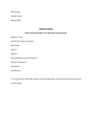
  • 36. Figure 5: The CubeSat after thirty minutes of <-76°F temperatures Results These tests were performed under the assumptions that the CubeSat will warm back up as it enters high altitude via infrared radiation and that the amount of time it spends in cold temperatures is approximately thirty minutes. This test also answered the question of how the device would behave if no heating source were added in (design constraints, weight, etc.). The arduino was powered after the tests in order to see if the electronics of a bare circuit board would still function after being exposed to cold temperatures, which resulted in with positive results. The temperatures did not have direct dry ice exposure since there was an equal gap of air around the surface area of the CubeSat. Both flight computers were activated at the same time. Formatted:Formatted:Formatted:Formatted: Left, Line spacing: 1.5 lines Comment [H6]:Comment [H6]:Comment [H6]:Comment [H6]: Consider rewording.
  • 37. Figures 5 and 6: These graphs show the data that both flight computers collected simultaneously. The slopes were observed more than the temperature vs. time. These graphs show that as time progresses, the temperature loss inside the Mylar decreased over time, whereas the foam continuously decreased without leveling out. Formatted:Formatted:Formatted:Formatted: Left Formatted:Formatted:Formatted:Formatted: Font: Bold
  • 38. D.4 Education/Public Outreach D.4.1 Overview of InSPIRESS D.4.2 Assigned InSPIRESS team information
  • 39. Associated Professors: Dr. Phillip Farrington Dr. Matthew Turner Dr. Michael “P.J.” Benfield Dr. Cassandra Runyon Dr. Jon Hakkila Science Team: Winslow Dibona- Principal Investigator Leisha Lopez-Ortiz Courtney Lawrence Jenna Snow Seth Able PPOOSSTT FFLLIIGGHHTT RREEVVIIEEWW AAPPRRIILL 2233,, 22001155 Engineering Team: Jesse Bracewell- Project Manager Lee Brooks- Chief Engineer Esra Arnason Leonard Farr Bradley Garrison Laura Langley Jacob Skaff Sam Winkler Technical Editors: Hannah Delp Emily Owen Comment [HD1]:Comment [HD1]:Comment [HD1]:Comment [HD1]: This document (Draft 2) contains Hannah Delp’s edits only StyleStyleStyleStyle Definition:Definition:Definition:Definition: Heading 3: Font: Not Bold, Indent: Left: 1" StyleStyleStyleStyle Definition:Definition:Definition:Definition: Heading 1: Font: Bold Formatted:Formatted:Formatted:Formatted: Font: 18 pt
  • 40. Mission Fact Sheet (2 pages) ***TBD***
  • 41. Table of Contents A. Science Investigation………………………………………………………………………………………... A.1 Science Background, Goals, and Objectives………………………………………….. A.1.1 Sending CubeSat into Atmosphere………………………………………….. A.1.2 Desired Information……………………………….……………………….... A.2 Science Requirements and Instrumentation…………………………………………… A.2.1 CofC Requirements (Traceability Matrix) ………………………………….. A.2.2 SMDC Requirements……………………………….……………………….. A.2.3 Final Instrumentation Used………………………………………………….. B. Mission Implementation……………………………….……………………………………… B.1 Mission Concept Solution……………………………….…………………………….. B.1.1 Final Design of CubeSat (CAD Model) …………………………………….. B.1.2 Concept of Operations……………………………………………………….. B.2 Mission Requirements and Constraints………………………………………………... B.2.1 Review of CalPolyCal Poly Design Requirements…………………………………… B.2.2 Impacts of Requirements……………………………….……………………. B.2.3 Verification of Met Requirements…………………………………………… B.3 Balloon Launch……………………………….……………………………………….. B.3.1 Launch Operations…………………………………………………………... B.3.2 Ascent Rate, Descent Rate, Descent Date, and Burst Altitude……………… B.3.3 Trajectory with Landing Site………………………………………………… B.3.4 Launch Recovery Plans ……………………………………………………... B.4 Data Analysis……………………………….…………………………………………. B.4.1 How Data will be Analyzed…………………………………………………. B.4.2 Conclusions from Data……………………………….……………………… B.5 Mission Evaluation and Lessons Learned……………………………………………... B.5.1 How Mission could have been Improved……………………………………. B.5.2 Problems from Launch/Recovery…………………………………………….
  • 42. B.5.3 Previous/Current Courses …………………………………………………… C. Management……………………………….…………………...……….………………………. C.1 Team Management Structure………………………………………………………….. C.1.1 Team Member Roles and Responsibilities…………………………………... C.2 Bill of Materials and Mission Cost……………………………………………………. C.2.1 Cost of Hardware and Components…………………………………………. C.2.2 Total Cost of Mission……………………………….……………………….. D. Appendices……………………………….……………………………….…………………… D.1 References……………………………….……………………………….…………… D.2 Team Member Resumes and Concurrence……………………………………………. D.2.1 Resumes from UAH and COFC Students…………………………………… D.3 Data and Supporting Analysis……………………………….………………………… D.3.1 Raw Data from Launch……………………………….…………………… D.4 Education/Public Outreach……………………………….…………………………… D.4.1 Overview of InSPIRESS……………………………….……………………. D.4.2 Assigned InSPIRESS Team Information…………………………………….
  • 45. A. Science Investigation A.1 Science Background, Goals and Objectives (Lee) A.1.1 Goal of sending Sending CubeSat into atmosphereAtmosphere A.1.2 Desired informationInformation A.2 Science Requirements and Instrumentation (Esra) The CubeSat has a specification document written by Cal Poly that gives requirements and constraints that the CubeSat must meet. This specification document gives many general requirements for CubeSats that will be launched into orbit., howeverHowever, several of those requirements and constraints are not applicable to this project and have been waived. The following items listed are the requirements and constraints that are applicable to this project from the Cal Poly CubeSat specification: items protruding from the CubeSat must be less than or equal to 6.5 mm, the total mass of the CubeSat must be less than 2,000 grams, the CubeSat width and length of a 2U must be 100 plus or minus 0.1 mm, and finally, the CubeSat height of a 2U must be 227 plus or minus 0.1 mm. These requirements can be seen in the House of Quality in Figure X. A.2.1 CofC requirements Requirements (Traceability Matrix) The science team at the College of Charleston (CofC) is a customer that has sent us science goals that had to be met. They supplied a science traceability that can be found in Table X. Currently, there are two science goals with objectives that have been set. The first science goal is to determine the scientific capabilities of the CubeSat utilizing the Nexus 5 smartphone, and the first science objective is to compare the imaging capabilities of the Nexus 5 with an external GoPro. The second science goal is to test the efficiency of cheap alternatives to pollution monitoring in areas with production plants, and the second science objective is to perform a statistical analysis of air pollutants in the atmosphere over Decatur, Alabama. Formatted:Formatted:Formatted:Formatted: Heading 1, Line spacing: single Formatted:Formatted:Formatted:Formatted: Heading 2, Indent: Left: 0", Line spacing: single Formatted:Formatted:Formatted:Formatted: Heading 3, Indent: Left: 0", Line spacing: single Formatted:Formatted:Formatted:Formatted: Heading 3, Indent: Left: 0", Line spacing: single Formatted:Formatted:Formatted:Formatted: Heading 2, Indent: Left: 0", Line spacing: single Formatted:Formatted:Formatted:Formatted: Left Formatted:Formatted:Formatted:Formatted: Heading 3, Indent: Left: 0", Line spacing: single Formatted:Formatted:Formatted:Formatted: Left
  • 46. The first science goal set by the science team at CofC required that an additional camera, specifically a GoPro Hero 3+, be used for comparison. The Nexus 5 camera will capture images in the visible spectrum, and the GoPro Hero3+ camera is for capturing a video of the entire flight, which will be compared to the camera on the Nexus 5 smartphone. The second science goal set by the science team at CofC required that measurements be taken, including measurements of atmospheric gasses and physical atmospheric properties, and the data must be stored in a workable format with readings in parts per million or parts per billion. Specifically, the atmospheric gases that are to be measured are carbon dioxide, carbon monoxide, nitrogen dioxide, ozone, and sulfur dioxide. These requirements can be seen in the House of Quality in Figure **X**. A.2.2 SMDC Rrequirements SMDC is funding the project and has set the baseline mission, which is to build a CubeSat utilizing the Nexus 5 smartphone. Additional requirements set by SMDC include the following: • exploiting Exploiting the Nexus 5 smartphone capabilities (specifically the smartphone’s camera) and integrating these technologies into the CubeSat, • Rremaining within a budget of $5,000, • Ensuring that the payload’s weight remains under 12 pounds according to FAA regulation (follow FAA weight requirements of less than 12 pounds (DIY Space Exploration), • Mmeeting the additional science goals set by CofC, • Llaunching the balloon on a high altitude weather balloon, • Ensuring that the CubeSat is durable enough to must survivesurvive the mission and be durable, and finally the • Recovering and analyzing and CubeSat’s data after the balloon launch. with all of the data that is to be analyzed must be recovered after the balloon launch. These requirements can be seen in the House of Quality in Figure **X** A.2.3 Final instrumentation usedUsed Formatted:Formatted:Formatted:Formatted: Left Formatted:Formatted:Formatted:Formatted: Left Formatted:Formatted:Formatted:Formatted: Heading 3, Indent: Left: 0", Line spacing: single Formatted:Formatted:Formatted:Formatted: Left Formatted:Formatted:Formatted:Formatted: Left, Bulleted + Level: 1 + Aligned at: 0.25" + Indent at: 0.5" Formatted:Formatted:Formatted:Formatted: Font: Formatted:Formatted:Formatted:Formatted: Font: Comment [HD2]:Comment [HD2]:Comment [HD2]:Comment [HD2]: Is this a citation? Formatted:Formatted:Formatted:Formatted: Font: Formatted:Formatted:Formatted:Formatted: Font: Comment [HD3]:Comment [HD3]:Comment [HD3]:Comment [HD3]: Did you mean “CubeSat”? Consider replacing. Formatted:Formatted:Formatted:Formatted: Font: Formatted:Formatted:Formatted:Formatted: Font: Formatted:Formatted:Formatted:Formatted: Font: Formatted:Formatted:Formatted:Formatted: Left, Indent: Left: 0.5" Formatted:Formatted:Formatted:Formatted: Left, Indent: Left: 0", Hanging: 0.5" Formatted:Formatted:Formatted:Formatted: Heading 3, Indent: Left: 0", Line spacing: single
  • 47. For the final instrumentationA a 2U CubeSat was used in the launch for the final instrumentation. The Cube met all size and weight requirements given by CalPolyCal Poly. One of the science goals from CofC required that was to use a GoPro be used to and take a video of the entire flight and to compare to the images taken on the Nexus 5 smartphone. A GoPro Hero 3+ was used for the final instrumentation and the Nexus 5 was utilized to taketook pictures continuously throughout the flight. For the second science goal, 4 four sensors were purchased to measure specific gas components in the atmosphere. The sensors were all connected to an Arduino board to store the data measured during the flight. B. Mission Implementation To achieve the mission, the payload will record images throughout the flight usinge the Nexus 5 smartphone to record images throughout the flight and record air composition throughout the flight using gas sensors from alpha sense. to record composition of air throughout the flight. The instruments must record and save the data during the flight. In addition, the instruments must survive the mission. To ensure this happens, it is necessary to design a CubeSat to Cal-Poly specs and print the design using a 3D printer. B.1 Mission Concept Solution (Bradley) To achieve these goals, the CubeSat design had to be large enough to house the major components of the gas sensor and the Nexus 5 while allowing the instruments to reach outside the CubeSat to gather data. Additionally, the CubeSat had to protect the electronics from exposure to the dynamic thermal effects of the flight, all while meeting the FAA regulations while still being cost effective. During the flight, the payload could be exposed to temperatures as low as -60˚ Celsius. Typically, most commercial electronics will shut off at a temperature around 0˚ Celsius, while industrial electronics will shut off at a temperature around -40 Celsius. B.1.1 Final design of CubeSat (CAD model) Formatted:Formatted:Formatted:Formatted: Left Formatted:Formatted:Formatted:Formatted: Left Formatted:Formatted:Formatted:Formatted: Heading 1, Line spacing: single Formatted:Formatted:Formatted:Formatted: Left Formatted:Formatted:Formatted:Formatted: Heading 2, Indent: Left: 0", Line spacing: single Formatted:Formatted:Formatted:Formatted: Left Formatted:Formatted:Formatted:Formatted: Heading 3, Indent: Left: 0", Line spacing: single
  • 48. To more effectively utilize the 3D printers available to the groups, the final design was a modular design that utilized a combination of three different part files. This allowed for easy change and replacement of sections of the CubeSat for design, layout, or instrument alterations. To solve the temperature issue, the CubeSat was lined on the inside by with layers of Mylar to retain the heat radiating from the electronics on the inside. There are two instruments that require holes for access outside of the CubeSat. One hole is for the gas sensors to collect air sample data, and the other hole is for the Nexus 5 lens to capture images during flight. The holes are designed into the location where the instruments will be housed. The instrumentation is inserted into the holes, and any gaps leading to the inside are sealed to retain heat. The structural walls of the CubeSat are designed to be 10 mm thick to provide structural stability and increased heat retention. B.1.2 Concept of operations Operations (Lee will do picture!) B.2 Mission Requirements and Constraints (Leonard) B.2.1 Review of the CalPolyCal Poly design Design requirementsRequirements The basic requirements that were set by CalPolyCal Poly were made in accordance with FCC and FAA restrictions. The physical restrictions require that the CubeSat be 10 cm x 10 cm x y cm, where y is 10, 15, 20, or 30, depending on its type (1U, 1.5U, 2U, and 3U). The CubeSat must also have a mass no greater than 1.33 kg, 2.00 kg, 2.66 kg, or 4.00 kg, respective to the body type. The center of gravity must be within 2 cm, 3 cm, 4 cm, and 7 cm from its neutral Z-axis. The Z-face of the CubeSat must be the side that gets inserted into the P-POD (Poly Pico satellite Orbital Deployer) if it is to be launched in this manner. The CubeSat must not have anything protruding on the outside any more than 6.5 mm (deployables are allowed, however, they must remain encapsulated until allowed to move). B.2.2 Impacts of the Rrequirements These requirements directly restrict dimensions and total allowable mass, which means that not only must a product remain in budget, but it must also perform all of its tasks and still remain in the physical set of rules. Since this project required the use of a cell phone, the 1U , with a( maximum external dimension Formatted:Formatted:Formatted:Formatted: Left Formatted:Formatted:Formatted:Formatted: Heading 3, Indent: Left: 0", Line spacing: single Formatted:Formatted:Formatted:Formatted: Heading 2, Indent: Left: 0", Line spacing: single Formatted:Formatted:Formatted:Formatted: Heading 3, Indent: Left: 0", Line spacing: single Formatted:Formatted:Formatted:Formatted: Left Formatted:Formatted:Formatted:Formatted: Heading 3, Indent: Left: 0", Line spacing: single Formatted:Formatted:Formatted:Formatted: Left
  • 49. equaling of 10 cm), was immediately ruled out. In order to have all major components fit inside, (keeping in mind the additional mass) the 2U was chosen as the CubeSat type. This decision also enables what all internal components may be added, not only for physical constraints but ease of access and necessary corrections. B.2.3 Verification of Met Design Requirements Verify that design meets requirements The first requirement, regarding the physical dimensions, was met by designing the outer 3-D printed shell to fit within the specified parameters. The second requirement, regarding the total mass of the system, was calculated to fall within the 2.00 kg limit by tabulating and adding up all the weights of each component, as well as the printed CubeSat itself. Finally, the third requirement, regarding the center of mass, requirement was satisfied by distributing equal weight from each component to key locations in order to balance out the device. B.3 Balloon Launch (Laura) B.3.1 Launch operationsOperations The launch operations are set up into three main sections. The first is preparation. Adequate preparation is an essential part of a successful launch because it allows for a much smoother launch process. Before the day of the launch, many steps need to be completed. The SPOT tracker, GoPros, and all other technical equipment should be tested. Also, the parachute should already be attached to twenty feet of cord on each side and rolled up. Strings used for tying the balloon neck should also be precut. The second step of launch operations is filling to fill the balloon. This process involves the balloon, helium, connecting hose, hose clamp, precut string loop, fish scale, and another piece of precut string. Once the hose is attached to the helium, the loop and clamp are placed on the hose. At this point, the hose is inserted into the balloon and the helium is turned on. The balloon will continue to fill up with helium until it has reached the desired lift. The lift can be determined by using the fish scale. Once the desired lift Comment [HD4]:Comment [HD4]:Comment [HD4]:Comment [HD4]: I'm not sure what this sentence means. Consider revising. Formatted:Formatted:Formatted:Formatted: Heading 3, Line spacing: single Formatted:Formatted:Formatted:Formatted: Heading 3, Indent: Left: 0", Line spacing: single Formatted:Formatted:Formatted:Formatted: Heading 3, Line spacing: single Formatted:Formatted:Formatted:Formatted: Left Formatted:Formatted:Formatted:Formatted: Heading 2, Indent: Left: 0", Line spacing: single Formatted:Formatted:Formatted:Formatted: Heading 3, Line spacing: single Formatted:Formatted:Formatted:Formatted: Heading 3, Indent: Left: 0", Line spacing: single Formatted:Formatted:Formatted:Formatted: Left Formatted:Formatted:Formatted:Formatted: Left
  • 50. is reached, the top of the neck of the balloon is tied closed off with string and the balloon is removed from the hose. The final step of the launch operations is to tieis to tie off the balloon neck and launch the balloonlaunch. At this point in the procedure, an individual should be holding the balloon just above where the first string was tied. Another tie will then be added at the bottom of the balloon neck. The neck will then be folded in half, with the loop in between the ties, and taped together. This will allow someone to hold the balloon by the loop. Once the balloon is tied off completely, the only remaining steps are to attach the payload, turn on the electronics, and launch the balloon. B.3.2 Ascent rateRate, descent Descent rateRate, and burst Burst altitudeAltitude A series of models are used to predict the rate that the payload will ascend, the altitude it will burst, and the rate is it will descend after is bursts. The first model used is the burst altitude model. The inputs for this model are the payload weight and the balloon lift. When entered into the spreadsheet, the ascent rate and the burst altitude are calculated. The second model used is the descent model. The inputs for this model are the payload mass and the diameter of the attached parachute. Once those values are put into the model, it will then calculate the descent rate of the payload after the balloon bursts. B.3.3 Trajectory with landing Landing siteSite The trajectory of the payload after the balloon bursts and the landing location are calculated using software found on the HabHub website cite. The inputs for this software are the latitude and longitude of the launch location, launch altitude, launch time, launch date, ascent rate, burst altitude, and descent rate. Once those parameters are entered, the software will show the predicted trajectory along with the landing site. The landing site is usually accurate within a mile or two. B.3.4 Launch recovery Recovery plansPlans Due to the fact that payload retrievals have been difficult in the past, two days are being set aside for the recovery. Also, the recovery team will consist of three team members (at the very minimum). Gear worn Formatted:Formatted:Formatted:Formatted: Left Formatted:Formatted:Formatted:Formatted: Heading 3, Indent: Left: 0", Line spacing: single Formatted:Formatted:Formatted:Formatted: Left Formatted:Formatted:Formatted:Formatted: Heading 3, Indent: Left: 0", Line spacing: single Formatted:Formatted:Formatted:Formatted: Left Formatted:Formatted:Formatted:Formatted: Heading 3, Indent: Left: 0", Line spacing: single Formatted:Formatted:Formatted:Formatted: Left
  • 51. by the team will consist of hiking boots and clothes suited for walking through the woods. The team will also bring other gear used to retrieve the payload, such as hatchets, a gpsGPS, a chainsaw, and the recovery kit provided by the professors. B.4 Data Analysis (Jacob) B.4.1 How the data Data will will be analyzedAnalyzed Launching the CubeSat provides an opportunity for data acquisition. The specific types of data that will be acquired and recorded during launch are the altitude of the CubeSat, the pressures and temperatures at these specific altitudes, and the concentrations of sulfur dioxide, nitrogen dioxide, carbon monoxide, and ozone gases in the atmosphere. Each of the recorded values can be traced to specific times and altitudes during flight. Two different sets of instruments will be. are used to gather altitude, temperature, and pressure. These instruments are the Nexus 5 smart phone, which utilizes the AndroSensor application, and the flight computer. The AndroSensor application is capable of running in the background of the Nexus 5 and obtaining seven different categories of data. These categories are location, acceleration, light, magnetic field, orientation, proximity, and battery status. The location is defined by values of latitude/longitude and altitude, and only two of these categories (location and acceleration) are relevant for data analysis. The numbers associated with latitude and longitude pinpoint the exact location of the CubeSat as it travels, depicting the path taken during flight. The values of altitude represent the height at a given latitude/ longitude the CubeSat reaches. Combined, these three values allow the location of the CubeSat to be determined at any moment during flight. The accelerometer data shows the “g-forces” achieved in each axial direction, thus showing the acceleration in the x, y, and z directions at any time during flight. The flight computer also measures latitude/longitude and altitude in addition to pressure and temperature. The pressure readings are equivalent to the amount of force being applied perpendicularly to the surface of the flight computer per unit area. The temperature values are equal to the temperature of the atmosphere at a given time. These values of pressure and temperature are unique to a specific height in the atmosphere. Formatted:Formatted:Formatted:Formatted: Heading 2, Indent: Left: 0", Line spacing: single Formatted:Formatted:Formatted:Formatted: Heading 3, Indent: Left: 0", Line spacing: single Formatted:Formatted:Formatted:Formatted: Left
  • 52. Four different gas sensors, which were purchased from AlphaSense, are also utilized for data acquisition. These sensors are the CO-A4, SO2-A4. O3-A4, and NO2-A4. Each sensor measures gas concentration by recording a voltage output. **NOT FINISHED** B.4.2 Conclusions from data Data (after After flightFlight) B.5 Mission Evaluation and Lessons Learned (Sam after flight) B.5.1 How the could mMission Could have Have been Been Iimproved B.5.2 Problems from launchLaunch/recoveryRecovery B.5.3 Previous/current Current courses Courses utilizedUtilized C. Management (Jesse) C.1 Team Management Structure (Jesse) Formatted:Formatted:Formatted:Formatted: Left Formatted:Formatted:Formatted:Formatted: Heading 3, Indent: Left: 0", Line spacing: single Formatted:Formatted:Formatted:Formatted: Heading 2, Indent: Left: 0", Line spacing: single Formatted:Formatted:Formatted:Formatted: Heading 3, Indent: Left: 0", Line spacing: single Formatted:Formatted:Formatted:Formatted: Heading 3, Indent: Left: 0", Line spacing: single Formatted:Formatted:Formatted:Formatted: Heading 3, Indent: Left: 0", Line spacing: single Formatted:Formatted:Formatted:Formatted: Heading 1, Line spacing: single Formatted:Formatted:Formatted:Formatted: Heading 2, Indent: Left: 0", Line spacing: single
  • 53. C.1.1 Team member Member roles Roles and responsibilitiesResponsibilities Name Role The University of Alabama in Huntsville Jesse Bracewell Project Manager Lee Brooks Chief Engineer Esra Arnason Supporting Engineer Leonard Farr Supporting Engineer Bradley Garrison Supporting Engineer Laura Langley Supporting Engineer Jacob Skaff Supporting Engineer Samuel Winkler Supporting Engineer Hannah Delp Technical Editor Emily Owen Technical Editor College of Charleston Formatted:Formatted:Formatted:Formatted: Heading 3, Indent: Left: 0", Line spacing: single
  • 54. Winslow DiBona Principal Investigator Leisha Lopez-Ortiz Co-Principal Investigator Seth Able Co-Investigator Courtney Lawrence Co-Investigator Jenna Snow Co-Investigator C.2 Bill of Materials and Mission Cost (Jesse) C.2.1 Cost of hardware and components (Not final) C.2.2 Total cost Cost of missionMission ***TBD*** Formatted:Formatted:Formatted:Formatted: Heading 2, Indent: Left: 0", Line spacing: single Formatted:Formatted:Formatted:Formatted: Heading 3, Indent: Left: 0", Line spacing: single Formatted:Formatted:Formatted:Formatted: Heading 3, Indent: Left: 0", Line spacing: single
  • 55. D. Appendices D.1 References Formatted:Formatted:Formatted:Formatted: Heading 1, Line spacing: single Formatted:Formatted:Formatted:Formatted: Heading 2, Indent: Left: 0", Line spacing: single
  • 56. D.2 Team Member Resumes and Concurrence D.2.1 Resumes from UAH and COFC studentsStudents Formatted:Formatted:Formatted:Formatted: Heading 2, Indent: Left: 0", Line spacing: single Formatted:Formatted:Formatted:Formatted: Heading 3, Indent: Left: 0", Line spacing: single
  • 57. JESSE BRACEWELL 11004 Everest Circle (931) 434-2005 Huntsville, AL 35803 jbracewell1225@gmail.com EDUCATION Bachelor of Science in Engineering May 2015 University of Alabama in Huntsville Huntsville, Alabama Motlow State Community College Lynchburg, Tennessee Major: Industrial & Systems Engineering RELATED COURSEWORK • Electrical Circuit Analysis • Engineering Graphics - MicroStation CAD • Industrial & Organizational Psychology • Management Systems Analysis • Manufacturing Systems & Facilities Design • Mechanics of Materials • Operations Research • Operations Systems Development & Management • Probability & Engineering Statistics • Production & Inventory Control Systems • Statistical Quality Control • Systems Simulation using Simio • Thermodynamics CERTIFICATIONS • Lean Enterprise • Six Sigma Green Belt WORK EXPERIENCE Manufacturing Design Engineer Co-Op September 2014 - Present Kappler, Inc. Guntersville, Alabama • Developing a process to monitor and report on HAZMAT suit pressure test readings using Six Sigma • Evaluating and developing wear fit patterns and correcting sizing charts • Completed a measurement system analysis of the pressure test kits and determined through statistical analysis that the machines have not been accurate for years • Developed ISO process and work instructions for performing air pressure tests on HAZMAT suits • Developed process to monitor and report on hot air tape machine parameters Engineering Intern May 2013 - September 2014 Twin City Fan Company, Clarage Division Pulaski, Tennessee • Managed implementation of the Epicor ERP system for the engineering department • Evaluated technical specifications and extracted necessary data for fan design purposes • Drafted advanced purchase requisitions, manufacturing data-books, and shipping instructions • Assisted in field-testing of jet fans installed inside the Caldecott Tunnels in California
  • 59. Esra Arnason 1313 Humes Avenue Huntsville, AL 35801 (256) 529-2931 esraarnason@gmail.com Education Qualifications University of Alabama in Huntsville Huntsville, AL B.S. Industrial and Systems Engineering Expected Graduation: May 2015 An ISE’s motto is to make things that are working, work even better, and that is how I see mostly everything I do. I have played soccer since I was 5 years old but I am always trying to find ways to improve myself physically and technically. I’m motivated to learn new things and I use that motivation and eagerness to educate myself everyday. Most important attribute in engineering is communication because I believe that it decides a project from working and failing. I always communicate with the people around me and make sure to listen to people as well. Relevant Coursework • Work design • Project Management • Statistical Analysis • Physics • Simulation • Workplace Organization • Thermodynamics • Facilities Design • Electrical Circuit • Operations Research Technical Skills • Major Software Packages: MS Office, Minitab • Lean Certified • Operating Systems: Mac OS, Unix, and MS Windows • Fluent in Icelandic and English • Know German and Danish Work Experience Jan 2014 – present University Fitness Center Huntsville, AL Front Desk Attendant • Do all paperwork for new and existing members • Communicate with members and help them Jun – Jul 2014 UAH Soccer Huntsville, AL Various soccer camps over the summer Coach • Assisted my head coach in training • Coaching various exercises during training. May – August 2011-2013 Margt Smatt Reykjavik, Iceland Stock Manager • Organized the stock area and made sure everything was maintained and in place. • Worked directly with factory workers who needed supplies from stock. • In charge of delivering and receiving products. Activities • UAH soccer player (2011-present)
  • 60. Leonard James Farr 137 Hillsdale Dr. Cell: (256) 585-4492 Gurley, AL. 35748 ljf0003@uah.edu ______________________________________________________________________________ Education: Bachelor of Science in Mechanical Engineering May 2015 University of Alabama in Huntsville Activities: Alpha Lambda Delta 2011 Sigma Alpha Pi 2012 Work Experience: NASA internship 2014 • Worked in the Component Development Area (Building 4656) at Marshall Space Flight Center as a volunteer intern over the summer of 2014. Performed over 450 working hours assisting a test engineer in implementing dozens of tests. Fully engaged in all aspects of test engineering including: test preparations, measurements, test implementation, and post-test analysis. Was also assigned an acoustic project that required data acquisition and Fourier analysis. Skills: • Basic calculus skills • Minor C++ computer programming skills • Microsoft programs (Word, Excel, PowerPoint, and Visio) • Constructing and designing (such as models, furniture, equipment, and robotics while provided with instructions) • Soldering • Computer Assembly and Troubleshooting • Minor IT skills • Significant Computer Aided Design skills (Solid Edge STD 4) • Basic electronic skills (physical wiring, diagram designing)
  • 61. B r a d l e y G a r r i s o n
  • 62. Laura Langley 403 Hillmont Dr. Huntsville, Alabama (205) 300-4850 LDL0004@uah.edu Education: Bachelor of Science in Mechanical Engineering May 2015 University of Alabama in Huntsville Related Coursework: • Principles of Measurement and Instrumentation – Programmed an Arduino Uno microcontroller board to measure heart rate in beats per minute using a Polar Heart rate monitor interface and chest strap Work Experience: UAH Career Office Aug 2013-Present Co-Op Ambassador • Facilitate outreach events to coach students on career development • Assist in the development and execution of career fair • Aide in the supervision of Interview Day on campus • Assist employers with on-campus presentations and recruiting Mercedes Benz US International Jan 2012-Aug 2013 Engineering Co-Op Student Supplier Quality Department Jan 2012-May 2012 • Developed and distributed reports informing employees of faults in the line • Assisted in the decision making process for hood design through coordinating the documentation for each method tested Series Planning Department Aug 2012-Dec 2012 • Facilitated the expansion of a line through data collection, parts gathering, documentation, bidding of project and managing the equipment installation • Completed an analysis of the PLCs in the paint shop as a preliminary step for a network change resulting in a large cost savings for the company • Created the specification and schedule for the network change in the paint shop Einführung Department (Dimensional Quality) May 2013-Aug 2013 • Implemented a velocity gauge as a new method of measuring door velocity by conducting an R&R study, training team members, and monitoring the process once placed on the line, resulting in less down time • Designed a database of mechanical drawings to be used by einführung team members to log all dimensional changes resulting in better communication and less down time. Honors and Affiliations: • Society of Women Engineers, (Treasurer) 2013-Present • Co-Op Ambassadors, (Secretary/Treasurer) 2013-Present • Tau Beta Pi, (Recording Secretary) 2014-Present • Co-Op Ambassador of the Year Award 2013-2014 Skills: Experience in: • SAP • Solid Edge • Matlab • MathCAD • Linux • Microsoft Office
  • 63. Jacob Skaff Education: Bachelor of Science in Aerospace Engineering May 2015 University of Alabama in Huntsville Major: Aerospace Engineering Projects: • Designed an experiment in a team of four involving the determination of thrust using motor RPM values o Received a grade of an A o Utilized an Arduino Uno, Hall Effect Sensors, and an RC helicopter o Calculated a thrust value that could be compared to a theoretical thrust value of the helicopter and was operationally successful • Designed and Fabricated an Autonomous Floor Cleaning Robot in a five member team o Team was graded best in class o Thoroughly documented all aspects of concept through operation • Designed and fabricated a model glider made from recyclable materials in a team of four o Project was required to fly a payload of pennies at least 2 meters o Project flew the farthest in class during the allotted test days • Designed a model SLS rocket with 20 unique parts and a model submarine with 15 unique parts utilizing the computer aided design software Solid Edge V.2 o Gained experience in computer aided design o Received a grade of an A Affiliations/ Awards • Alpha Lambda Delta Honor Society 2012-Present • Sigma Alpha Pi Leadership Honor Society 2013-Present • American Society of Mechanical Engineers 2011-Present Relevant Coursework • Thermodynamics I • Electrical Circuits • Fluid Mechanics • Mechanics of Materials • Fundamentals of Aerodynamics • Rocket Propulsion • Air Breathing Propulsion • Aerospace Structures • Compressible Aerodynamics • Analysis of Engineering Systems • Engineering Economy Technical Skills • CAD software: Solid Edge V.2 • Computer programming software: Mathcad • Computer programming software: Matlab • Arduino Programming • Microsoft Office
  • 64. S A M U E L L . W I N K L E R 602 Excel Circle Brownsboro, AL 35787 256.541.5941 slw0023@uah.edu EDUCATION Bachelor of Science in Engineering/Chemistry Minor University of Alabama in Huntsville, Huntsville, AL Expected August 2015 Bachelor of Science in Engineering United States Military Academy, West Point, NY March 2012 WORK EXPERIENCE CrossFit L1 Trainer/USAW Coach, CHAMP Performance Training, Madison, AL August 2013-Present • Provide positive and safe environment for clients; Conduct health assessments • Learn excellent communication skills when working with clients to assess progress and convey feedback • Responsible for educating clients of CrossFit’s program and goals through introductory classes Telecommunications Technician, Crowder Wire and Cable, Huntsville, AL March 2012-Dec. 2013 • Communicate regularly with customers to handle complaints, concerns, and resolve issues • Provide cost estimates and invoices to customers • Install, repair, test, and terminate various forms of telecommunication and wiring for proper connection INTERNSHIPS Engineering Co-Op, Parker Hannifin, Instrumentation Products Division, Boaz, AL April 2013-Present • Design and implement industrial manufacturing equipment and machines to increase plant efficiency • Responsible for maintaining tooling logistics through software • Develop 3D computer automated design drafts of machine parts and assemblies RESEARCH American Astronautical Society’s 7th Wernher Von Braun Symposium Entrant June 2014- Oct. 2014 • Alternative methods of measuring water potabilitiy in third world countries • Team effort began as project requirement for MAE311: Principles of Measurement and Instrumentation COMMUNITY SERVICE Big Brother, Big Brothers Big Sisters of North Alabama, Huntsville, AL March 2014-Present • Mentor and support a child emotionally for approximately twelve to fourteen hrs/month Volunteer, Huntsville Hospital Endoscopy Center, Huntsville, AL Sept. 2014-Present • Assist with patient transportation, Volunteer, LifeSouth Community Blood Center, Huntsville, AL Feb. 2014 • Assist with blood drive; Help with elementary school presentation on education of blood donation Volunteer, Panoply, Huntsville, AL April 2014 • Assist festival goers through games, movement, and creative activities Competition Assistant, CrossFit CHAMP 2014 Throwdown, Madison, AL February 2014 • Conduct setup, breakdown, and judgment of competition events Competition Assistant, Muscle Mayhem 2014 Throwdown, Madison, AL February 2014 • Conduct setup, breakdown, and judgment of competition events during a fundraising event SHADOWING Dr. Patrick Baldwin, M.D., Emergency Dispatch, Crestwood Hospital, Huntsville, AL March 2014-May 2014 • Shadowed 4 hrs/wk for 5 wks; Observed the appropriate methods to approach and interact with patients • Learned the basics of charting and a multitude of diagnoses and treatments ACTIVITIES AND LEADERSHIP A-Futures Scholar, Stimulated interest in STEM topics to high school students, UAH Athlete, Track and Field Team, USMA August 2010-April 2011 Competitor, CrossFit, Olympic Lifting, Madison, AL April 2013-Present Member, ASRHA and Medical Careers Club, UAH January 2014-Present Member/Graduate, 101 st Airborne Division Sabaulaski Air Assault School, Camp Smith, NY June 2011 Math Tutor, College Reading and Learning Association, USMA August 2011-March 2012 Team Leader, Responsible for development of fourth class cadets, USMA August 2011-March 2012
  • 65. Hannah Delp 256-797-8788 hcd0003@uah.edu ____________________________________________________________________________ Key Words Technical Writing, Communications, Graphic Design, Editing, Marketing, Art Handling Education University of Alabama in Huntsville Huntsville, AL B.A., Technical Communications Expected Graduation: Fall 2016 • Minors: Web Communications and Public History • GPA: 3.93/4.0 Relevant Coursework • Technical Writing/Editing • Business Communications • Principles of Marketing • Intro to Graphic Design • Macro/Microeconomics • Historical Research Methods • Computer Programming in Business • Human Communication Technical Skills • Operating Systems: Windows 98, Vista, and Windows 7 • Adobe Illustrator/Photoshop, Python • Writing and Editing Skills: proposals, progress reports, business letters, style guides, and other related documents Work Experience Huntsville Museum of Art Huntsville, AL May 2013 – Present Exhibitions and Collections Assistant • Coordinates with curators other assistants to install exhibitions. • Assists with collections management and documentation. Tea with Thee by Victoria Madison, AL May 2013 – August 2013 Server/Cashier Tuscaloosa Museum of Art Tuscaloosa, AL February 2013 – May 2013 Intern • Researched background information on pieces in the permanent collection. • Generated articles for the museum’s website. Tellini’s Italiano Huntsville, AL June 2012 – August 2012 Server/Cashier Honors and Activities • President of the Public History Club at UAH • Member of Phi Kappa Phi (National Multi-disciplinary Honor Society), Kappa Pi (International Honorary Art Fraternity), and Phi Alpha Theta (International History Honor Society) Awards • Recipient of the Shelbie J. King Scholarship and the Super Scholar Transfer Scholarship
  • 66. Emily Owen 256-655-3264 Objective Current student that is a self-motivated, positive team player with experience in sales, writing, marketing, and healthcare. Work Experience Directv, Huntsville, Alabama USA Customer Service Representative 05/2012 - 10/2013 Answer calls pertaining to customer’s accounts up to and including sales, technical appointments, technical issues, and general customer service.• Computer skills: typing and understanding the Directv accounts system. Elite Eye Care, Huntsville, Alabama USA Administrative/Technician 06/2011 - 04/2012 Administrative Assistant• Filing insurance.• Make appointments and answer phones.• Fill out medical paperwork as needed. As a Technician Assistant to the doctors, I prepped patients, took their stats and fixed eyeglasses. Sam's Club, Huntsville, Alabama USA Customer Service/Marketing 05/2009 - 08/2012 Marketing, Customer Service• Ability to bake and package for customers.• Providing assistance with credit cards and applications.• Traveling up to an hour from my employer to represent Sam’s Club and process memberships for the company. Education Hazel Green High School Hazel Green, Alabama USA Advance Diploma , GPA: 3.2 1997 - 2001 Jacksonville State University Jacksonville , Alabama English, GPA: 3.0 2001 - 2003 University of Alabama Huntsville Huntsville, Alabama English, GPA: 3.2 2014 - Present SKILLS • Microsoft Office Suite (Word, Excel, Outlook, PowerPoint) • Numerous Company-Specific Software Programs • Great attention to detail • Able to accurately check guest identification • Excellent people and customer service skills • Time-management skills • Ability to work in a fast-paced environment and remain calm while doing so
  • 67. • Good leadership skills • Able to accept criticism • Good decision-making and problem-solving skills • Marketing- phone and business sales. • Ability to type 65 wpm. Winslow DiBona
  • 72. D.3 Data and Supporting Analysis Appendix D.3.1: CubeSat Insulation Test Report Abstract In order to keep the electronic components functioning while in high-altitude temperatures, insulation must be implemented utilized to keep the heat trapped inside for as long as possible. The only two sources of insulation that was immediately available were regular insulation foam and a sheet of Mylar. A test was designed to The purpose of the test was to see which of the two insulation mediums would be more efficient in decreasing heat loss. A specially designed CubeSat was 3D printed with two separate compartments, one with for the Mylar and the other with for the insulation foam. For the final test, two similar flight computers and identical thermocouple sensors were placed in each compartmentt with identical thermocouple sensors. The entire test article was placed inside a Yeti cooler with a broken-down piece of dry ice in order to expose the CubeSat to temperatures that are found at high altitude. The final result showed the Mylar insulation decreasing in temperature in a decreasing slope, and thusly, slowly decreasing the loss of heat as time increases. These tests that used dry ice were more economical and efficient when testing for insulation efficiency than launching high-altitude balloons and retrieving the balloons hours after launch. Objective The objective was to get a quick result regardingquickly determine which form of insulation was better, not the best. Although these results are very similar, the Mylar insulation was slightly more effective than the foam insulation. The final results of the insulation show that the Mylar had a decreasing slope, meaning its temperature loss decelerates compared to the foam. Testing Procedure Formatted:Formatted:Formatted:Formatted: Heading 2, Indent: Left: 0", Line spacing: single Formatted:Formatted:Formatted:Formatted: Heading 3, Indent: Left: 0", Line spacing: single Formatted:Formatted:Formatted:Formatted: Left Formatted:Formatted:Formatted:Formatted: Left
  • 73. Rather than launching the CubeSat with the high- altitude balloons and then retrieving them, it was determined that ground-level, deep-freezing tests would be more economical and efficient since results were needed immediately. To determine real-time results, the variable of different starting temperatures and measurements was removed by using two identical measuring devices (the thermocouples with flight computers that each group was given), which were activated and placed into the cooler simultaneously. Figure 1: The dry ice maxed beyond -76 °F which means that it was much cooler than the targeted temperature. The actual temperature could not be determined but it was below natural high-altitude temperatures. The picture above (Figure 1) was a thermal image taken of the dry ice to confirm the temperature zone. The Flir One thermal camera maxed out at -76° F. Figure 2: The CubeSat had two compartments: an empty compartment with Mylar, and another compartment filled with foam and an internal tub (orange plastic print) to give heat resistance to the outside environment. Formatted:Formatted:Formatted:Formatted: Left Formatted:Formatted:Formatted:Formatted: Line spacing: single Formatted:Formatted:Formatted:Formatted: Left Formatted:Formatted:Formatted:Formatted: Line spacing: single
  • 74. Because the data was unreliable due to too many variables, tThe test that was performed on February 10th was redone on February 12th12th. because the data was not reliable since there were too many variables. The earlier tests made use of a single flight computer, which was placed in both compartments at different times. This meant that the temperature readings and the overall temperature of the CubeSat had too many variables influencing the final results. Figure 3: Since the earlier tests had too many variables, they served more as a proof of concept. These images above show the temperature readings of both compartments with the Styrofoam cover removed. The left side was the foam side; the right side was the Mylar side. The Mylar was very reflective, and although the reflection of light also makes a reflection of infrared radiation, these images were taken at night with minimal lighting (all warm signatures are actual heat signatures and not reflections). Figure 4: The CubeSat after thirty minutes of <-76°F temperatures Formatted:Formatted:Formatted:Formatted: Left Formatted:Formatted:Formatted:Formatted: Line spacing: single Formatted:Formatted:Formatted:Formatted: Left
  • 75. Results These tests were performed under the assumptions that the CubeSat will warm back up as it enters high altitude via infrared radiation and that the amount of time it spends in cold temperatures is approximately thirty minutes. This test also answered the question of how the device would behave if no heat source were added (design constraints, weight, etc.). The arduino was powered after the tests in order to see if the electronics of a bare circuit board would still function after being exposed to cold temperatures, which resulted in positive results. The CubeSat did not have direct dry ice exposure since there was an equal gap of air around the surface area of the CubeSat. Both flight computers were activated at the same time. Figures 5 and 6: These graphs show the data that both flight computers collected simultaneously. The slopes were observed more than the temperature vs time. These graphs show that, as time progresses, the temperature loss inside the Mylar decreased over time, whereas the foam continuously decreased without leveling out. Formatted:Formatted:Formatted:Formatted: Left Formatted:Formatted:Formatted:Formatted: Font: Bold
  • 76. Appendix D.3.2: CubeSat Assembly Procedure Forewarnings: -• It is recommended that the CubeSat be Ppractice CubeSat assembled assembly (without adhesives) (no adhesives) prior to actual construction. -• Lay all similar pieces side by side in an organized fashion, if any. -• Label pieces -• Glue in peg sockets and between walls Formatted:Formatted:Formatted:Formatted: Heading 3, Indent: Left: 0", Line spacing: single Formatted:Formatted:Formatted:Formatted: Font: (Default) Arial Formatted:Formatted:Formatted:Formatted: Line spacing: Double Formatted:Formatted:Formatted:Formatted: Font: 11 pt Formatted:Formatted:Formatted:Formatted: Line spacing: Double, Bulleted + Level: 1 + Aligned at: 0" + Indent at: 0.25" Formatted:Formatted:Formatted:Formatted: Font: 11 pt Formatted:Formatted:Formatted:Formatted: Font: 11 pt Formatted:Formatted:Formatted:Formatted: Font: 11 pt Formatted:Formatted:Formatted:Formatted: Font: (Default) Times New Roman
  • 77. Parts List: Wall A (x3) Sensor Plate D (x1) Wall B (x3) Sensor Holder (x1) Face Plates C (x2) Phone Wall E (x1) Phone Socket F (x1) Formatted:Formatted:Formatted:Formatted: Font: (Default) Arial
  • 78. CubeSat Construction Procedure 1) Piece together two Wall B’’s. 1) 2) Piece together two Wall A’s. 3) Piece together the sensor plate D and the the sensor holder. (Screw in sensors after adhesive has dried). Be sure to glue together both pieces in the order that both thicknesses match. Formatted:Formatted:Formatted:Formatted: Font: (Default) Arial Formatted:Formatted:Formatted:Formatted: Font: 10 pt Formatted:Formatted:Formatted:Formatted: Font: 11 pt Formatted:Formatted:Formatted:Formatted: Normal, No bullets or numbering Formatted:Formatted:Formatted:Formatted: Font: 11 pt Formatted:Formatted:Formatted:Formatted: Font: 11 pt Formatted:Formatted:Formatted:Formatted: Font: 11 pt Formatted:Formatted:Formatted:Formatted: Font: 11 pt
  • 79. 4) Attach the result of step 3 to a side wall B. 5) C onstruct the phone section together by first attaching a wall A and the phone wall E together. 6) Attach phone socket F at the shown location on the same side with the perpendicular nubs. Attach phone into the sockets after adhesive has dried. 7) File out the nubs on the narrow sides of the phone section. Formatted:Formatted:Formatted:Formatted: Font: 11 pt Formatted:Formatted:Formatted:Formatted: Font: 11 pt Formatted:Formatted:Formatted:Formatted: Font: 11 pt Formatted:Formatted:Formatted:Formatted: Font: 11 pt Formatted:Formatted:Formatted:Formatted: Font: 11 pt Formatted:Formatted:Formatted:Formatted: Font: 11 pt
  • 80. 8) Attach the sensor section and the wall section on to the bottom section of the CubeSat. 9) Attach the two face plates (C) to both ends of the CubeSat. Formatted:Formatted:Formatted:Formatted: Font: 11 pt Formatted:Formatted:Formatted:Formatted: Font: 11 pt Formatted:Formatted:Formatted:Formatted: Font: 11 pt Formatted:Formatted:Formatted:Formatted: Font: 11 pt
  • 81. 10) Place the phone section on top of the CubeSat. DO NOT use glue. Use screws to fix the two pieces together in the future. 11) Insert the Mylar insulation into the CubeSat. 12) Insert all electric components inside. 13) Activate all components, then and seal the CubeSat using screws on the phone section to the wall section and sensor section. 14) Place CubeSat inside paracord net. 15) Attach paracord net to the sling on the payload frame. Formatted:Formatted:Formatted:Formatted: Font: 11 pt Formatted:Formatted:Formatted:Formatted: Font: 11 pt Formatted:Formatted:Formatted:Formatted: Line spacing: Double Formatted:Formatted:Formatted:Formatted: Font: 11 pt