30 years poly-ceramic rotors and water lubricated screw
supply_program compressors 2007
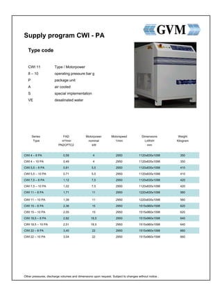
1. Supply program CWI - PA
660
660
640
640
620
620
560
560
420
420
410
410
350
350
Weight
Kilogram
2950
2950
2950
2950
2950
2950
2950
2950
2950
2950
2950
2950
2950
2950
Motorspeed
1/min
1515x960x1598223,04CWI 22 – 10 PA
1515x960x1598223,40CWI 22 – 8 PA
1515x960x159818,52,51CWI 18,5 – 10 PA
1515x960x159818,52,82CWI 18,5 – 8 PA
1515x960x1598152,05CWI 15 – 10 PA
1515x960x1598152,36CWI 15 – 8 PA
1220x835x1098111,39CWI 11 – 10 PA
1220x835x1098111,71CWI 11 – 8 PA
1120x835x10987,51,02CWI 7,5 – 10 PA
1120x835x10987,51,12CWI 7,5 – 8 PA
1120x835x10985,50,71CWI 5,5 – 10 PA
1120x835x10985,50,81CWI 5,5 – 8 PA
1120x835x109840,49CWI 4 – 10 PA
1120x835x109840,59CWI 4 – 8 PA
Dimensions
LxWxH
mm
Motorpower
nominal
kW
FAD
m³/min
PN2CPTC2
Series
Type
Type code
CWI 11 Type / Motorpower
8 – 10 operating pressure bar g
P package unit
A air cooled
S special implementation
VE desalinated water
Other pressures, discharge volumes and dimensions upon request. Subject to changes without notice .
2. Supply program CWI - PW
660
660
640
640
620
620
560
560
420
420
410
410
350
350
Weight
Kilogram
2950
2950
2950
2950
2950
2950
2950
2950
2950
2950
2950
2950
2950
2950
Motorspeed
1/min
1220x835x1228223,04CWI 22 – 10 PW
1220x835x1228223,40CWI 22 – 8 PW
1220x835x122818,52,51CWI 18,5 – 10 PW
1220x835x122818,52,82CWI 18,5 – 8 PW
1220x835x1228152,05CWI 15 – 10 PW
1220x835x1228152,36CWI 15 – 8 PW
1220x835x1098111,39CWI 11 – 10 PW
1220x835x1098111,71CWI 11 – 8 PW
1120x835x10487,51,02CWI 7,5 – 10 PW
1120x835x10487,51,12CWI 7,5 – 8 PW
1120x835x10485,50,71CWI 5,5 – 10 PW
1120x835x10485,50,81CWI 5,5 – 8 PW
1120x835x104840,49CWI 4 – 10 PW
1120x835x104840,59CWI 4 – 8 PW
Dimensions
LxWxH
mm
Motorpower
nominal
kW
FAD
m³/min
PN2CPTC2
Series
Type
Type code
CWI 11 Type / Motorpower
8 – 10 operating pressure bar g
P package unit
W water cooled
S special implementation
VE desalinated water
Other pressures, discharges volumes and dimensions upon request. Subject to changes without notice.
3. Supply program CWF - PA
12501900x1175x18682950305,1CWF 30 – 8 PA
4050
3500
3500
2600
2600
2500
2500
2100
1850
1850
1540
1540
1470
1470
1380
1380
1270
1270
1250
Weight
Kilogram
2970
2970
2970
2970
2970
2970
2970
2970
2950
2950
2950
2950
1470
2950
1470
1450
2950
1450
2950
Speed
Motor/Male-
Rotor 1/min
3180x1400x203025033,5CWF 250 – 10 PA
3180x1400x203020029CWF 200 – 10 PA
3180x1400x203020033CWF 200 – 8 PA
3180x1400x203016024,5CWF 160 – 10 PA
3180x1400x203016027,5CWF 160 – 8 PA
2440x1190x174013220CWF 132 – 10 PA
2440x1190x174013222,5CWF 132 – 8 PA
2440x1190x174011015,6CWF 110 – 10 PA
At the moment only as CWS 110 – 8 PA available.CWF 110 – 8 PA
2440x1190x17409013,1CWF 90 – 10 PA
2440x1190x17409014,9CWF 90 – 8 PA
2440x1190x17407510,5CWF 75 – 10 PA
2440x1190x17407512,5CWF 75 – 8 PA
2250x1190x1870557,8CWF 55 – 10 PA
2250x1190x1870558,7CWF 55 – 8 PA
2250x1190x1870456,6CWF 45 – 10 PA
2250x1190x1870457,4CWF 45 – 8 PA
1900x1175x1868375,47CWF 37 – 10 PA
1900x1175x1868376,4CWF 37 – 8 PA
1900x1175x1868304,6CWF 30 – 10 PA
Dimensions
LxWxH
mm
Motorpower
nominal
kW
FAD
m³/min
PN2CPTC2
Series
Type
Type code
CWF 45 Type / Motorpower
8 – 10 operating pressure bar g
P package unit
A air cooled
S special implementation
VE desalinated water
Other pressures, discharge volumes and dimensions upon request. Subject to changes without notice.
4. Supply program CWF - PW
12001900x1175x14502950305,1CWF 30 – 8 PW
4050
3500
3500
2600
2600
2500
2500
2100
1850
1850
1560
1560
1410
1410
1300
1300
1250
1250
1200
Weigth
Kilogram
2950
2950
2950
2950
2950
2950
2950
2950
2950
2950
2950
2950
2950
2950
1470
1450
2950
1450
2950
Speed
Motor/Male-
Rotor 1/min
3180x1400x203025033,5CWF 250 – 10 PW
3180x1400x203020029CWF 200 – 10 PW
3180x1400x203020033CWF 200 – 8 PW
3180x1400x203016024,5CWF 160 – 10 PW
3180x1400x203016027,5CWF 160 – 8 PW
2450x1150x173013220CWF 132 – 10 PW
2450x1150x173013222,5CWF 132 – 8 PW
2450x1150x173011015,6CWF 110 – 10 PW
At the moment only as CWS 110 – 8 PW available.CWF 110 – 8 PW
2450x1150x17309013,1CWF 90 – 10 PW
2450x1150x17309014,9CWF 90 – 8 PW
2450x1150x17307510,5CWF 75 – 10 PW
2450x1150x17307512,5CWF 75 – 8 PW
2250x1213x1515557,8CWF 55 – 10 PW
2250x1213x1515558,7CWF 55 – 8 PW
2250x1213x1515456,6CWF 45 – 10 PW
2250x1213x1515457,4CWF 45 – 8 PW
1900x1175x1450375,47CWF 37 – 10 PW
1900x1175x1450376,4CWF 37 – 8 PW
1900x1175x1450304,6CWF 30 – 10 PW
Dimensions
LxWxH
mm
Motorpower
nominal
kW
FAD
m³/min
PN2CPTC2
Series
Type
Other pressures, discharge volumes and dimensions upon request. Subject to changes without notice.
Type code
CWF 45 Type / Motorpower
8 – 10 operating pressure bar g
P package unit
W water cooled
S special implementation
VE desalinated water
5. Supply program CWS - PA
12701900x1175x18681660 – 3320302,5 – 5,1CWS 30 – 8 PA
12701900x1175x18681470 – 2950302,4 – 4,6CWS 30 – 10 PA
44503180x1500x20301620 -360030018 – 40CWS 300 – 10 PA
4120
4120
3600
3600
2730
2730
2580
2580
2190
2190
1950
1950
1670
1670
1570
1570
1430
1430
1330
1330
Weigth
Kilogram
1550 – 3180
1600 – 3500
1400 – 2670
1500 – 3000
1450 -3000
1600 – 3200
1800 – 3600
1450 – 3050
1450 – 2980
1450 – 3160
1660 – 3350
1860 – 3680
1450 – 2900
1450 – 3160
2250 – 4500
1470 – 3000
1900 – 3800
2100 – 4200
1800 – 3600
2025 – 4050
Speed
Motor/Male-
Rotor 1/min
min-max.
3180x1400x203025016 – 35CWS 250 – 10 PA
3180x1400x203025018 – 39CWS 250 – 8 PA
3180x1400x203020015 - 29CWS 200 – 10 PA
3180x1400x203020016 - 33CWS 200 – 8 PA
3180x1400x203016012 – 24,5CWS 160 – 10 PA
3180x1400x203016014 – 27,5CWS 160 – 8 PA
2440x1190x174013210 - 20CWS 132 – 10 PA
2440x1190x174013211 – 22,5CWS 132 – 8 PA
2440x1190x17401107,5 – 15,6CWS 110 – 10 PA
2440x1190x17401108,5 – 17,5CWS 110 – 8 PA
2440x1190x1740906,5 – 13,1CWS 90 – 10 PA
2440x1190x1740907,5 – 14,9CWS 90 – 8 PA
2440x1190x1740755 – 10,5CWS 75 – 10 PA
2440x1190x1740756 – 12,5CWS 75 – 8 PA
2250x1190x1870553,8 – 7,8CWS 55 – 10 PA
2250x1190x1870554,3 – 8,7CWS 55 – 8 PA
2250x1190x1870453,5 – 6,6CWS 45 – 10 PA
2250x1190x1870453,7 – 7,4CWS 45 – 8 PA
1900x1175x1868372,7 – 5,47CWS 37 – 10 PA
1900x1175x1868373,2 – 6,4CWS 37 – 8 PA
Dimensions
LxWxH
mm
Motorpower
nominal
kW
FAD
m³/min
from / to
PN2CPTC2
Series
Type
Other pressures, discharge volumes and dimensions upon request. Subject to changes without notice.
Type code
CWS 55 Type / Motorpower
8 – 10 operating pressure bar g
P package unit
A air cooled
S special implementation
VE desalinated water
7. SCOPE OF DELIVERY / CWF-CWS-Series
Compressor package
The screw compressor functions 100 % oil-free, single-stage with water-injection cooling and lubrication.
The compression heat for PA machines is discharged by means of an air-water heat exchanger, for PW
machines, by means of a water-water plate heat exchanger.
The screw compressor is delivered ready for operation, mounted on a torsionally-stiff baseframe with
elastic machine legs for installation without any need for foundation. All monitoring, cooling and control
facilities have been incorporated, the connection of the water and gas systems has been conceived in
antirust design, and the compressor package has been equipped with a sound-absorbing casing. The
switch cabinet has been integrated in the sound-absorbing hood and is easily accessible from outside.
Operating state indicators
- final temperature of compression
- min. network pressure
- max. network pressure
- operating state
- readiness for operation
- on-load operating hours
- total operating hours
- maintenance of air filter
- lubrication of bearings
- water filter
- min. level
- max. level
- conductivity max.
Monitoring and safety system with shutdown function
- final temperature of compression exceeded
- final pressure too high
- malfunction of driving motor
- malfunction of fan motor
- false sense of rotation
- differential pressure/water filter
- water loss/water level
Drive system CWF - CWS
The electric motor transfers the torque through an elastic coupling directly to the male rotor. The
compressor air end is flanged to the motor.
Compressor air end CWF - CWS
The casing is made of aluminium casting and the patented rotors of ceramic polymer. The anti-corrosive
materials ensures reliable and almost maintenance-free operation by means of water injection. The axial
and radial bearings are greased by a hydrodynamic water lubrication. They are maintenance-free and
equipped with a protective device ensuring that a lubricating film has been established before the start of
the main motor. The sealing of the drive shaft is realised by a rotating mechanical seal.
Regulation of suction
Full-load/no-load regulation with unloading. The full no-load starting of the compressor is realized by a
suction regulator. This suction regulator serves for a economically favourable start operation, which in
connection with a star-delta circuit prevents current peaks.
Refrigeration
The particular feature of the water-injected screw compressor is a very low final temperature of
compression, exceeding the ambient temperature only by approx. 14 °C in case of air cooling and
approx. 5°C in case of water cooling. Large dimensioning of the water cooler in combination with the
patented water injection makes the after cooler required for other compressor system superfluous.
8. Noise level
The optimal construction of the compression system, cease after-cooler, the rotors made from ceramic-
polymer-compound material and the cooling air ducting will ensure an extremly low noise level.
Quality of compressed air
The water injected compression system guarantees the manufacture of oil- and dustfree compressed
air without installed after-purification plants. There is no comparable compression system available,
ensuring such a specifically favourable and high qualitiy generation of compressed air without additional
filtration required.
Water injection
The combined water stock tank is constructed with an integrated cyclone system for separating the water
from the compressed air. The tank and the components inside of the tank are made from special steel.
Treatment of injection water
In addition to the five-stage water filter, a full-flow ionization is provided in the internal water circuit. This
unit functions automatically without any foreign energy supply and is to prevent crystalline sedimentations
in interaction with the controlled conducitivity. The circulating water is led through filter and ionization
approx. 6 times per minute. That is, the existing ions are permanently charged positively and may absorb
possible negative ions, leading them to the filter (international patents pending).
Ion-Clean conductivity control
A mixed-bed ion exchanger has been incorporated in the package, ensuring the generation of fully
desalted water. In combination with a conducitivity meter with thermal compensation, an electronic
system ensures that the conductivity, measured at the point of injection, lies in between 10 and 20 µS/25
°C. So, exorbitant occurrence of calcium, magnesium ions etc. is prevented in any state of the process
water system whatever. In addition, monitoring of the influence of CO2 (carbonic acid), in particular, of
the free carbonic acid not bonded to hydrogencarbonates is safely guaranteed in the framework of
conducitivity.
Drive
The electric motor is designed for an ambient temperature of 40 °C, if desired with cold conducters
deliverable. It is equipped with regreasing device for bearings.
Switch cabinet
Sheet-steel enclosed in IP 55 with master switch, control and power unit of the compressor wired on
modular terminals, control via microprocessor, conducitivity of the injection water is indicated by diodes.