SlideShare a Scribd company logo
1 of 24
Download to read offline
HYDROVAR FROM XYLEM HAS BECOME THE NAME OF CHOICE FOR CONTROLLING
THE EFFICIENCY OF FIXED SPEED PUMPS.
HYDROVAR
WELCOMETHE
5TH
GENERATION
02
In 1993 HYDROVAR was
as the world’s first pump
Now the 5th
generation h
setting a new standard.
HYDROVAR 1st
generation
HYDROVAR 5th
generation
03
Typical applications.
Domestic/
Industrial Water S
upply
Fire Fighting
Food
&
Beverage Geothermal
Irrigati
on / Agricultural
Mining / Drainag
e
/Dewatering
W
ater Displays / Fou
ntains/Features
HV
AC
Municip
alWaterSupply
established
controller.
has arrived and is
04
HYDROVAR is an intelligent controller that matches pump performance to demand.
It controls the speed of a standard IEC motor by converting the fixed voltage and
frequency from the power supply line.
It can be fitted easily to any new pump system or retrofitted to existing pumps using the
fast and easy “clip and play” mounting clamps.
Pump systems are very often oversized for the application and therefore using much
more energy than needed.
With energy savings of up to 70% at partial loads alone, the typical investment payback
period is less than 2 years, depending on energy costs and pump operating times.
A motor running at 80% of its maximum speed uses 48% less energy and slashes carbon
emissions.
The controls available include constant pressure, system curve, constant flow or via
an external signal. In addition to these functions HYDROVAR can do things that are
normally only performed by the most advanced computerized control systems such as:
stopping the pump or pumps at zero demand; stopping the pump or pumps in case
of water failure; allowing protection against dry running; a standard feature of a 2nd
required input value that allows change over between two different pressure settings
via an external switch; sensor failure and over temperature of inverter and motor which
protects the pump and motor from under or overvoltage.
Other features include: automatic test starts; auto cyclic change of lead and lag pump
units; a memory for any inverter fault signals; an operating hours run counter; two levels
of password protection if required.
What is HYDROVAR
capable of?
Control for constant
pressure
Control to match a
system curve
Control for constant flow Control according to
an external signal
05
Available from 1.5 to 22 kW in single or
three phase, pump or wall mounted.
Pump mounted version will fit on any
standard IEC motor. Optismised cooling
of the HYDROVAR depending on
the power and the speed of the pump is
guaranteed by the motor fan.
Easy to commission, easy to setup and
operate with the easy start up menu
allowing you to walk through every step.
New features include a larger screen
display.
No external control panel needed.
No water hammer. The steady operation
of the pump in partial loads also prevents
water hammer, which normally arises
in the start/stop operation of full speed
pumps.
Lower starting current. High current peaks
are prevented by adjusting the start ramp
times as you can in a soft starter.
Multi-pump capability comes as standard
which allows control from 1 to 8 pumps.
Communicating with a central control
system is also possible via an RS485
interface, and each HYDROVAR contains
an individual microprocessor which
operates independently if a failure occurs.
Modbus and BACnet protocol fitted as
standard.
Lower noise from the pump because of
lower speeds during operation. There
is less noise in the pipeline and valves
because of pump performance to
the actual demand, and control along the
system curve.
Less wear and less mechanical stress
because of lower speed of the pumps
during operation and no additional load
in the starting moment because of the soft
start feature.
HYDROVAR product
overview.
Can link up to 8 pumps
using HYDROVAR.
Multi controller, cascade relay:
This is where you can fit one HYDROVAR
and up to five slave fixed speed pumps
which are switched to on/off on demand.
Using this type of system requires a
premium card and an external control panel.
Inverter
InverterInverter Inverter InverterInverter Inverter InverterInverter
06
The 5th
generation takes H
of robustness, safety, secu
Easy and safe accessibility
for the wiring harness
•	Separate wiring chamber with
a dedicated cover
•	All internal electronic components
are protected
Advanced motor control
•	Reduced heating of the motor
•	Extended lifetime of the motor
•	Due to built-in selectable software
protection, motor PTC can be optional
•	Minimised drive losses
Additional features of HYDROVAR:
•	HYDROVAR can be fitted on any
standard IEC motor up to 22 kW. Wall
mounting kits are available on request
•	No separate microprocessor is needed
•	No separate control panels are needed
•	No large pressure vessels are needed
•	No anti-con heaters are needed as these
are built in as standard
•	IP55
•	Error logs and real time and date calendar
•	Quality aluminum body
Range extension
•	The new models are:
	 1.5kW 3ph 380-460V
	 1.5kW to 11kW 3ph 208- 240V
	 3 kW and 4 kW 1ph 208-240V
07
HYDROVARtoanewlevel
urity and performance.
Easier to commission and to operate
•	Quick start-up menu allowing faster set-up
•	Larger LCD display with additional
control parameters
•	28 languages within the software
•	Pre-programmed parameter for standard
motors
HYDROVAR built in protection
•	Over/under voltage
•	Overcurrent/output short protection
•	Low water protection (by using pressure/
flow/float switch)
•	Sensor failure
•	Motor over temperature
•	Inverter over temperature
•	Minimum threshold/conveyer limit
Extended communication capabilities
•	BACnet and Modbus as standard
•	Wi-Fi card as an option
THDi filter embedded
•	Will extend the lifetime of equipment
•	No need for line reactor filters
•	Better quality of the grid power
•	Reduced heating of the cables
Control offering
•	Multi-pump capability come as standard
from 1-8 pumps
•	Constant pressure
•	Constant flow
•	System curve
•	Via an 4-20ma or 0-10V external signal
•	Automatic test and auto change over
•	It stops at zero demand
•	Integrated soft start/stop
•	Complete set of analog and digital
input/output
•	The premium card also allows an
additional 2 x inputs and 2 x outputs
08
EcoDesign
EN50598-1-2
EN 50598
The Ecodesign directive has been in
place since 2011 and introduced
minimum requirements for the efficiency
of AC motors. These requirements have
been gradually intensified. The EN 50598
standard defines efficiency classes for
motor systems.
EN 50598-1
Integration of the frequency converter and
motor into an “extended product” IE – a
pump.
EN 50598-2
Similar to the IE classification of motors
(where all Lowara motors are IE3),
EN50598-2 introduces IE classes for
frequency converters and IES classes for
frequency converters plus motor systems
(known as power drive systems). This new
regulation was published in early 2015.
Classes IE0 – IE2 for frequency converters.
Classes IES0 – IES2 for power drive systems
(frequency converter plus motor).
The EN 50598-2 standard defines efficiency
classes from IE0 – IE2 for frequency
converters. If a frequency converter has
25% greater losses than the reference value
of IE1 then it is classified as IE0; if it has 25%
lower losses than the reference value of IE1
then it is classified as IE2.
This new standard covers frequency
converters that meet the following criteria:
- Power rating from 0.12 kW to 1000kW.
- Voltage range from 100V to 1000V.
Legal requirements
In Europe the minimum efficiency
performance standards (MEPS) are
expected to be at IE1 level in 2018.
HYDROVAR is classified as IE2 which is
the most efficient in class; this efficiency
measure includes the losses due to the built
in RFI filters and DC chokes which come as
standard up to 22kW in size.
When HYDROVAR is connected to a Lowara
IE3 motor then the system will achieve the
highest IES class – IES2.
Ecodesign directive.
IE1
IE0
EN 50598-2
IE-classes for frequency converter
IE1 = Reference
IE2
+25%
Reduction
-25%
Reduction
IES1
IES0
EN 50598-2
IES classes for motor-frequency
converter systems
IES1 = Reference
IES2
+20%
Reduction
-20%
Reduction
IE1
IE0
EN 50598-2
IE-classes for frequency converter
IE1 = Reference
IE2
+25%
Reduction
-25%
Reduction
IES1
IES0
EN 50598-2
IES classes for motor-frequency
converter systems
IES1 = Reference
IES2
+20%
Reduction
-20%
Reduction
09
Hydrovar fulfills the product standard EN61000-3-2 for single
phase and EN61000-3-12 for three phase.
Harmonics.
HYDROVAR comes with built in Total Harmonic Distortion current filters (THDi) to reduce
harmonic interference. In most cases this is sufficient to avoid voltage pollution. Additional
harmonic suppression may be required due to grid conditions or when multiple drives
are installed.
Harmonics are associated with any load that uses a rectifier-based power supply such as
radio or TV, computers and lighting ballasts – and other domestic white goods such as
washing machines, microwaves and ovens which draw current in a non-sinusoidal fashion.
The level of harmonics reflected back to the supply network is usually regulated by the
electricity supply utility. Harmonics are voltages and currents in the electrical system at
frequencies that are multiples of the fundamental frequency.
Generally the greater the amount of installed electronic power switching equipment on
site, the greater degree of harmonic distortion.
Put simply, harmonics reduce reliability, affect product quality and increase operating costs.
EMC.
HYDROVAR fulfills the product standard EN61800-3:2004 + A1: 2012 under the 1st
Environment which includes domestic premises and buildings/facilities which are directly
connected to a low voltage (e.g. 230/400V) mains supply which also supplies buildings
used for domestic purposes.
HYDROVAR Vector Control (HVC).
The HVC automatically and continuously adjusts the output frequency and voltage to optimize
the motor operation over a broad range of speeds and loads. For variable torque pump
applications, there is no need to de-rate the motor for any operational speed.
HVC is superior to the traditional PWM control schemes in the following ways:
Full rated motor voltage is provided at rated frequency.
The output current wave shape is an almost a perfect sine wave.
Automatically chooses motor control for the operating conditions:
The low speed switching pattern ensures reliable starts and smooth low speed operation.
The high speed switching pattern minimizes switching losses and maximizes drive
efficiency. The HVC maximizes the performance and the efficiency of the system while
minimized the heating of the motor which results in a longer life.
HYDROVAR harmonics and EMC.
10
Automatic Motor Parameter Identification (AMPI).
AMPI is an algorithm to measure the electrical motor parameters on a motor at rest. This
means that AMPI itself does not supply any torque. AMPI is useful when commissioning
systems and optimising the adjustment of the frequency converter to the applied motor.
Lowara 2 pole high efficiency IE3 50Hz surface motors have parameters already preset as
default.  This feature is particularly used where the default setting does not apply to the
connected motor. The benefit of this feature is to maximize the control and efficiency of
the HYDROVAR for any given standard asynchronous motor.
Motor thermal protection.
HYDROVAR has built in software thermal control (STC) so no need for fitting motor PTCs.
The STC function is initialized at 1.125 x rated motor current and rated motor frequency.
The STC function provides class 20 motor overload protection in accordance with the
NEC. Motor thermal protection prevents the motor from overheating. The STC function is
an electronic feature that simulates a bimetal relay that is based on internal measurements.
The characteristic is shown in the following figure.
11
Optional components.
Premium card	 Card which will allow up to 5 slave pumps and additional 	
			 analog and 2 x inputs and 2 x outputs
Wi-Fi card	 To connect HYDROVAR via wireless connection
Sensors	 Different sensors are available from pressure, differential, 		
			 temperature, flow indicator or level sensor
Wall mounting kit	 Stainless steel wall mounting kit fitted with external 		
			 cooling fan and connection box
Fan cowl mounting ring	 Used for plastic fan cowls, 140mm or 155mm
			 in diameter
Motor filters	 -
Motor cables	 Cable that is ready to connect to the unit and motor
12
Single-speed drives start motors abruptly,
subjecting the motor to high torque and
current surges up to 10 times the full-load
current. In contrast, variable-frequency
drives offer a "soft start" capability,
gradually ramping up a motor to operating
speed. This lessens mechanical and
electrical stress on the motor system and
can reduce maintenance and repair costs
and extend motor life.
Other advantages of frequency
controllers
Lower starting current
Reduced mechanical stress
Flexibility of operation
Reduced noise levels
Payback costs in energy and payback
Reduced hardware requirements – starters,
power factor correction, metering/
monitoring,PI control,etc.no longer required
Water consumption in a hotel is not uniform during the
day. The pumping system should be able to match the
real needs of the users.
Benefits.
H 0.00
Hours
H 24.00H 12.00 H 18.00H 6.00
25 %
% of Flow
50 %
75 %
100 %
Water usage
13
15% INSTALLATION
10% PURCHASE COST
30% MAINTENANCE
45% OPERATING COSTS
<< This picture shows the typical LCC of
a 15 year life cycle of a pump.
Life Cycle Cost (LCC)
calculation.
As a general guide these figures are
realistic, but the percentages could change
from job to job, depending on the size /
type / and complexity of the installation.
The idea here is to give the consultant the
perspective that if you save on the energy
cost – this makes up a huge part of the
LCC, and therefore saving energy will save
money.
Calculation of LCC = Life Cycle Costs
LCC = Cic
+ Cin
+ Ce
+ Co
+ Cm
+ Cs
+ Cd
+ Cenv
Cic
	 Initial costs, purchase price
			 (pump, pipe, valves, auxiliary)
Cin
	 Installation and commissioning
Ce
	 Energy costs
Co
	 Operating costs
Cm
	 Maintenance costs
Cs
	 Downtime, loss of production
Cd
	Decommissioning
Cenv
	Environmental
It’s also important to look at Life Cycle Costs
(LCC).
Pumping systems account for nearly 20%
of the world’s electrical energy usage.
Some studies show that between 30 and
50% of energy consumed by a pump
could be saved through the use of fitting a
VSD. The main economic reasons for using
LCC is because companies are becoming
increasingly aware of the environmental
impacts and looking at energy efficiency
as one way of reducing emissions and
preserving natural resources.
Existing pumping systems provide a
greater opportunity for saving money not
just by fitting VSDs but looking at installing
new pumps which have higher hydraulic
efficiencies and also motors which have
changed over the years to become
more efficient. This is due to the strict EU
regulations which have been adopted over
the past and coming years to save energy
usage.
14
The graph below is an indication of the benefits of fitting HYDROVAR to each fixed speed
motor.
Please check with your local country government efficiency project schemes; grants may
be available towards installing inverter technology on electric motors to achieve substantial
energy savings by reducing motor speeds.
Energy efficiency
funding schemes.
Notes: we have based some assumptions on the examples of fitting HYDROVAR onto fixed speed motors:
1. The cost of energy, we have assumed 0.22 euros per kW.
2. We have used two % of the full flow rate being 60% and 80%.
3. We have used 48 weeks per year, 5 days per week, 12 hours per day.
4. We have based an average cost of the HYDROVAR.
5. We have assumed an average installation fitting cost.
With all this information we can use an estimated payback for fitting a HYDROVAR VSD in terms of time, money and power saved.
HYDROVAR cost savings examples
Size of motor
for pump unit
3 kW 3 kW 5.5 kW 5.5 kW 11 kW 11 kW 22 kW 22 kW
Cost of
energy (€)
0.22 0.22 0.22 0.22 0.22 0.22 0.22 0.22
Flow in % of full
rated flow
60 80 60 80 60 80 60 80
Weeks per year 48 48 48 48 48 48 48 48
Days per
week running
5 5 5 5 5 5 5 5
Hours per
day running
12 12 12 12 12 12 12 12
Cost of single
HYDROVAR (€)
1,400 1,400 1,700 1,700 2,500 2,500 2,800 2,800
Cost of
installation (€)
300 300 300 300 300 300 300 300
Interest rate (%) 3 3 3 3 3 3 3 3
Power used 0.65 kW 1.54 kW 1.19 kW 2.82 kW 2.38 kW 5.63 kW 4.75 kW 11.26 kW
Power saved 1.53 kW 1.24 kW 2.80 kW 2.28 kW 5.61 kW 5.56 kW 11.21 kW 9.13kW
Money saved in
euros per year
968.65
euro's
788.45
euro's
1,775.85
euro's
1,445.50
uro's
3,551.71
euro's
2,890.99
euro's
7,103.42
euro's
5,781.98
euro's
Energy saved
4,402.94
kWh
3,583.87
kWh
8,072.06
kWh
6,570.43
kWh
16,144.13
kWh
13.140,86
kWh
32,288.26
kWh
26,281.73
kWh
Payback 1.83 years 2.26 years 1.28 years 1.58 years 0.81 years 1 years 0.45 years 0.55 years
15
HYDROVAR start-up screen
Start-up menu.
START
LANGUAGE: SELECTION
MOTOR POWER
MOTOR SUPPLY
PRESET MOTOR
PUMP ADDRESS
SOFTWARE THERMAL CONTROL (STC OF THE MOTOR)
OPERATING MODE: E.G. SERIAL OR SYNCHRONOUS
CONSTANT PRESSURE OR CONSTANT DIFFERENTIAL PRESSURE
COMMENT: BY DEFAULT SOME PARAMETERS WILL
CHANGE (RAMPS, SENSORS, HYSTERESIS ETC…)
AFTER 10 MINUTES IF THE START UP IS NOT
COMPLETED THE HV WILL DISPLAY A
WARNING SHOWING THE CUSTOMER
TO COMPLETE IT.
DIMENSION UNIT: (BAR, PSI, M3
/H, G/MIN, MH2O, FT,…, %)
COMPLETED START UP ?
REQUIRED VALUE
START VALUE
MIN. THRESHOLD
DELAY TIME
AUTO - START
COMPLETED START UP ?
SENSOR RANGE PRESSURE TRANSMITER RANGE
DATE - TIME (REAL TIME CLOCK / CALENDAR)
16
Energy savings
in HVAC systems.
Energy is the largest cost of running any pump, with the biggest potential savings.
HYDROVAR works with your system to make it efficient. This intelligent variable speed
drive controls the pump exactly according to the current requirements of the user.
Compared to an unregulated system, HYDROVAR saves up to 70% of the energy
consumption (as tested by TÜV Austria, vogw0312-PIR-ZR). The smooth regulation
at optimal operation increases not only the efficiency but also the life of the system’s
components and reduces maintenance costs.
17
Dimension and
weight.
Model A
Model Type Model Size Maximum Weight
2.015 A 5,6 kg (12.31 lbs)
2.022 A 5,6 kg (12.31 lbs)
3.015 A 5,6 kg (12.31 lbs)
3.022 A 5,6 kg (12.31 lbs)
4.015 A 5,6 kg (12.31 lbs)
4.022 A 5,6 kg (12.31 lbs)
4.030 A 5,6 kg (12.31 lbs)
4.040 A 5,6 kg (12.31 lbs)
Model B
Model Type Model Size Maximum Weight
2.030 B 10,5 kg (23.14 lbs)
2.040 B 10,5 kg (23.14 lbs)
3.030 B 10,5 kg (23.14 lbs)
3.040 B 10,5 kg (23.14 lbs)
3.055 B 10,5 kg (23.14 lbs)
4.055 B 10,5 kg (23.14 lbs)
4.075 B 10,5 kg (23.14 lbs)
4.110 B 10,5 kg (23.14 lbs)
Model C
Model Type Model Size Maximum Weight
3.075 C 15,6 kg (34.39 lbs)
3.110 C 15,6 kg (34.39 lbs)
4.150 C 15,6 kg (34.39 lbs)
4.185 C 15,6 kg (34.39 lbs)
4.220 C 15,6 kg (34.39 lbs)
18
Electrical Data.
Model
Type
Rated
output
Nominal input
voltage
Model
Size
Max Input
current (A)
Efficiency
Rated (%)
typical
Output
voltage (V)
Max output
current (A)
Output
frequency (Hz)
2.015 1.5 kW 208-240±10%
(Single phase)
A 11.6 A 94% 0-240
(Three phase)
7.5 A 15-70 (Hz)
2.022 2.2 kW
208-240±10%
(Single phase)
A 15.1 A 93.5%
0-240
(Three phase)
10 A 15-70 (Hz)
2.030 3 kW
208-240±10%
(Single phase)
B 22.3 A 93.5%
0-240
(Three phase)
14.3 A 15-70 (Hz)
2.040 4 kW
208-240±10%
(Single phase)
B 27.6 A 93.5%
0-240
(Three phase)
16.7 A 15-70 (Hz)
3.015 1.5 kW 208-240±10%
(Three phase)
A 7 A 96% 0-100%
of supply voltage
7.5 A 15-70 (Hz)
3.022 2.2 kW
208-240±10%
(Three phase)
A 9.1 A 96%
0-100%
of supply voltage
10 A 15-70 (Hz)
3.030 3 kW
208-240±10%
(Three phase)
B 13.3 A 96%
0-100%
of supply voltage
14.3 A 15-70 (Hz)
3.040 4 kW
208-240±10%
(Three phase)
B 16.5 A 96%
0-100%
of supply voltage
16.7 A 15-70 (Hz)
3.055 5.5 kW
208-240±10%
(Three phase)
B 23.5 A 96%
0-100%
of supply voltage
24.2 A 15-70 (Hz)
3.075 7.5 kW
208-240±10%
(Three phase)
C 29.6 A 96%
0-100%
of supply voltage
31 A 15-70 (Hz)
3.110 11 kW
208-240±10%
(Three phase)
C 43.9 A 96%
0-100%
of supply voltage
44 A 15-70 (Hz)
4.015 1.5 kW
380-460±15%
(Three phase) A 3.9 A 96%
0-100%
of supply voltage 4.1 A 15-70 (Hz)
4.022 2.2 kW
380-460±15%
(Three phase)
A 5.3 A 96.5%
0-100%
of supply voltage
5.7 A 15-70 (Hz)
4.030 3 kW
380-460±15%
(Three phase)
A 7.2 A 96.5%
0-100%
of supply voltage
7.3 A 15-70 (Hz)
4.040 4 kW
380-460±15%
(Three phase)
A 10.1 A 96.5%
0-100%
of supply voltage
10 A 15-70 (Hz)
4.055 5.5 kW
380-460±15%
(Three phase)
B 12.8 A 97%
0-100%
of supply voltage
13.5 A 15-70 (Hz)
4.075 7.5 kW
380-460±15%
(Three phase)
B 16.9 A 97%
0-100%
of supply voltage
17 A 15-70 (Hz)
4.110 11 kW
380-460±15%
(Three phase)
B 24.2 A 97%
0-100%
of supply voltage
24 A 15-70 (Hz)
4.150 15 kW
380-460±15%
(Three phase)
C 33.3 A 97%
0-100%
of supply voltage
32 A 15-70 (Hz)
4.185 18.5 kW
380-460±15%
(Three phase)
C 38.1 A 97%
0-100%
of supply voltage
38 A 15-70 (Hz)
4.220 22 kW
380-460±15%
(Three phase)
C 44.7 A 97%
0-100%
of supply voltage
44 A 15-70 (Hz)
19
Halve the cost of running a
booster set in five steps.
Retrofitting.
Retrofiitting the ‘plug and play’ HYDROVAR units to a fixed speed
booster set not only eliminates the need for a control panel but
also introduces a soft start function, that when combined with the
benefits of running a pump at a variable speed, can prolong the
life of the pump and the water system. By reducing the in-rush
current when the pump is turned on, parts such as motor bearings
and pipe fittings are protected from hydraulic shock that can cause
cavitation and breakdown.
2
Step Two: Clamping the HYDROVAR
into place.
The HYDROVAR sits directly onto the pump
and utilises the cool air emitted from the fan
vents to prevent overheating. This means
that there is no need for an additional
cooling unit, keeping the footprint of the
HYDROVAR to a minimum and not utilising
valuable wall space. Fixings are located
on the outer casing so no need to remove
the casing of the HYDROVAR as previous
models. Use the four mounting clamps
provided together with the central post
pin and secure it to the metal fan cowl of
the pump unit. The clamps are designed
to fit all IEC motors. Stainless steel ring
supports are available for motors fitted with
plastic fan cowls. Wall mounted versions are
available as an option.
1
A
E
B
F
C
G
D
H
Step One: Assessment of the installation
site and the current pump activity.
Before any HYDROVAR installation,the
site and its current equipment should be
assessed to determine the current level of
energy being consumed and the kW of the
motor.From here,the installer can calculate
how much the booster set or heating pump
is costing on an annual basis by calculating
0.22 Euros per hour for each kilowatt of
energy consumed. An 11kW single pump
will therefore cost €2.42 per hour to run at full
speed.Once this cost has been multiplied
by the number of pumps that are in use,the
installer can explain in monetary terms what
an average 50 per cent reduction in energy
consumption would save the end user.
Connecting a HYDROVAR couldn’t be simpler; here we demonstrate
an installation in just five steps:
3
Step Three: Pump Terminal Wiring.
After attaching the cable glands to the
exposed gland plate on the left hand side
of the HYDROVAR, unscrew and remove
the front of the pump motor terminal
box. Take the HYDROVAR connection
cables (purchased separately or made
using standard wires and connections)
and feed the motor terminal end of the
cable through the cable entry points,
connecting it to the relevant terminals. If
you are retrofitting the unit to an existing
booster set then the power supply
needs to be rerouted directly into the
HYDROVAR. No PCT is required and
this is now done by the internal software
of the HYDROVAR. Once this is done,
reattach the terminal front cover, ensuring
that the water seal is correctly in place.
4
Step Four: HYDROVAR wiring.
Remove the wiring chamber cover and
pass the other end of the connection
cable through the cable inlet on the left
hand side of the HYDROVAR, connecting
it to the relevant power supply and signal
wires. Once this is done, connect the
transducer cable (also called the sensor
or pressure transmitter) to the HYDROVAR
through the same gland plate. The loose
end of the transducer must then be
connected to the pipe as close to the
pump as possible.
5
Step Five: Completion
and programming.
After replacing the terminal cover lid
of the HYDROVAR unit, programme
the required bar pressure using the
buttons and the screen. Depending on
the number of pumps in the booster set,
some very simple programming may
be required. This is detailed clearly in
the operating instructions manual. The
first screen after powering up the unit
will be the quick start guide after setting
these parameters; the HYDROVAR will
automatically begin its soft start and work
to the system requirements. 21
22
Other products
available in
the Xylem porftolio.
cod.191007781-P10/16
1) The tissue in plants that brings water upward from the roots;
2) a leading global water technology company.
We’re a global team unified in a common purpose: creating innovative solutions to meet our world’s water needs.
Developing new technologies that will improve the way water is used, conserved, and re-used in the future is central
to our work. We move, treat, analyze, and return water to the environment, and we help people use water efficiently, in
their homes, buildings, factories and farms. In more than 150 countries, we have strong, long-standing relationships with
customers who know us for our powerful combination of leading product brands and applications expertise, backed by
a legacy of innovation.
For more information on how Xylem can help you, go to www.xyleminc.com
For information and technical support
Xylem Service Italia Srl
Via Dottor Vittorio Lombardi 14
36075 - Montecchio Maggiore (VI) - Italy
Tel. (+39) 0444 707111
Fax (+39) 0444 491043
www.lowara.com
Lowara, HYDROVAR, Xylect are trademarks or registered trademarks of Xylem Inc. or one of its subsidiaries.
All other trademarks or registered trademarks are property of their respective owners.
Xylem Service Italia Srl reserves the right to make modification without prior notice.
© 2016 Xylem, Inc.
Xylem |’zīl m|e

More Related Content

What's hot

Nidec asi variable frequency drives
Nidec asi variable frequency drivesNidec asi variable frequency drives
Nidec asi variable frequency drivesNidec Corporation
 
Catalog Biến tần Frenic ACE Mini (Fuji Electric) - Beeteco.com
Catalog Biến tần Frenic ACE Mini (Fuji Electric) - Beeteco.comCatalog Biến tần Frenic ACE Mini (Fuji Electric) - Beeteco.com
Catalog Biến tần Frenic ACE Mini (Fuji Electric) - Beeteco.comBeeteco
 
Electro-Hydraulic Linear Actuators for Industrial Valves
Electro-Hydraulic Linear Actuators for Industrial ValvesElectro-Hydraulic Linear Actuators for Industrial Valves
Electro-Hydraulic Linear Actuators for Industrial ValvesClassic Controls, Inc.
 
Intelligent mcc Siemens
Intelligent mcc Siemens Intelligent mcc Siemens
Intelligent mcc Siemens Praveen Patil
 
Vlt® hvac drives a complete range of advanced solutions
Vlt® hvac drives a complete range of advanced solutionsVlt® hvac drives a complete range of advanced solutions
Vlt® hvac drives a complete range of advanced solutionsDanfoss India
 
Scada presentation
Scada presentationScada presentation
Scada presentationAmit Kumar
 
Beijer hvac inverter_h2_brochure
Beijer hvac inverter_h2_brochureBeijer hvac inverter_h2_brochure
Beijer hvac inverter_h2_brochureElectromate
 
Catalog biến tần Frenic eHVAC - beeteco.com
Catalog biến tần Frenic eHVAC - beeteco.comCatalog biến tần Frenic eHVAC - beeteco.com
Catalog biến tần Frenic eHVAC - beeteco.comBeeteco
 
Monitoring genset systems in standby mode to assure reliable startup
Monitoring genset systems in standby mode to assure reliable startupMonitoring genset systems in standby mode to assure reliable startup
Monitoring genset systems in standby mode to assure reliable startupM.S. Jacobs & Associates
 
Related RE work (LT, 11kV & 33kV)
Related RE work (LT, 11kV & 33kV)Related RE work (LT, 11kV & 33kV)
Related RE work (LT, 11kV & 33kV)SAJAL KUMAR BAG
 
Wind generator monitoring and control system_Jakab Zsolt
Wind generator monitoring and control system_Jakab ZsoltWind generator monitoring and control system_Jakab Zsolt
Wind generator monitoring and control system_Jakab ZsoltJakab Zsolt
 
Manual de Danfoss 2800
Manual de Danfoss 2800Manual de Danfoss 2800
Manual de Danfoss 2800Camilo Avelino
 

What's hot (20)

Nidec asi variable frequency drives
Nidec asi variable frequency drivesNidec asi variable frequency drives
Nidec asi variable frequency drives
 
Riello aros-central-transformer-based-solar-inverters
Riello aros-central-transformer-based-solar-invertersRiello aros-central-transformer-based-solar-inverters
Riello aros-central-transformer-based-solar-inverters
 
ABB Relay
ABB RelayABB Relay
ABB Relay
 
Retrofit
RetrofitRetrofit
Retrofit
 
Scada
ScadaScada
Scada
 
Catalog Biến tần Frenic ACE Mini (Fuji Electric) - Beeteco.com
Catalog Biến tần Frenic ACE Mini (Fuji Electric) - Beeteco.comCatalog Biến tần Frenic ACE Mini (Fuji Electric) - Beeteco.com
Catalog Biến tần Frenic ACE Mini (Fuji Electric) - Beeteco.com
 
Electro-Hydraulic Linear Actuators for Industrial Valves
Electro-Hydraulic Linear Actuators for Industrial ValvesElectro-Hydraulic Linear Actuators for Industrial Valves
Electro-Hydraulic Linear Actuators for Industrial Valves
 
Intelligent mcc Siemens
Intelligent mcc Siemens Intelligent mcc Siemens
Intelligent mcc Siemens
 
Vlt® hvac drives a complete range of advanced solutions
Vlt® hvac drives a complete range of advanced solutionsVlt® hvac drives a complete range of advanced solutions
Vlt® hvac drives a complete range of advanced solutions
 
Scada presentation
Scada presentationScada presentation
Scada presentation
 
Beijer hvac inverter_h2_brochure
Beijer hvac inverter_h2_brochureBeijer hvac inverter_h2_brochure
Beijer hvac inverter_h2_brochure
 
Axpert hivert series mv drive
Axpert hivert series mv driveAxpert hivert series mv drive
Axpert hivert series mv drive
 
Catalog biến tần Frenic eHVAC - beeteco.com
Catalog biến tần Frenic eHVAC - beeteco.comCatalog biến tần Frenic eHVAC - beeteco.com
Catalog biến tần Frenic eHVAC - beeteco.com
 
Monitoring genset systems in standby mode to assure reliable startup
Monitoring genset systems in standby mode to assure reliable startupMonitoring genset systems in standby mode to assure reliable startup
Monitoring genset systems in standby mode to assure reliable startup
 
Related RE work (LT, 11kV & 33kV)
Related RE work (LT, 11kV & 33kV)Related RE work (LT, 11kV & 33kV)
Related RE work (LT, 11kV & 33kV)
 
Wind generator monitoring and control system_Jakab Zsolt
Wind generator monitoring and control system_Jakab ZsoltWind generator monitoring and control system_Jakab Zsolt
Wind generator monitoring and control system_Jakab Zsolt
 
H100
H100H100
H100
 
Nidec asi silcovert gn
Nidec asi silcovert gnNidec asi silcovert gn
Nidec asi silcovert gn
 
ritesh (2)
ritesh (2)ritesh (2)
ritesh (2)
 
Manual de Danfoss 2800
Manual de Danfoss 2800Manual de Danfoss 2800
Manual de Danfoss 2800
 

Similar to Hydrovar

04 V4- K TSM 380V 50Hz.pdf
04 V4- K TSM 380V 50Hz.pdf04 V4- K TSM 380V 50Hz.pdf
04 V4- K TSM 380V 50Hz.pdfAirconDoctor
 
Catalog Biến tần Frenic Aqua Fuji-Beeteco.com
Catalog Biến tần Frenic Aqua Fuji-Beeteco.comCatalog Biến tần Frenic Aqua Fuji-Beeteco.com
Catalog Biến tần Frenic Aqua Fuji-Beeteco.comBeeteco
 
catalog Frenic AQUA catalog - www.haophuong.com
catalog Frenic AQUA catalog - www.haophuong.comcatalog Frenic AQUA catalog - www.haophuong.com
catalog Frenic AQUA catalog - www.haophuong.comCTY TNHH HẠO PHƯƠNG
 
двигатели MGE Grundfos с IE5
двигатели MGE Grundfos с IE5двигатели MGE Grundfos с IE5
двигатели MGE Grundfos с IE5Arve
 
Fuji tu dong hoa catalog frenic-aqua-fuji-dienhathe.org
Fuji tu dong hoa catalog frenic-aqua-fuji-dienhathe.orgFuji tu dong hoa catalog frenic-aqua-fuji-dienhathe.org
Fuji tu dong hoa catalog frenic-aqua-fuji-dienhathe.orgDien Ha The
 
Varaible frequency drive
Varaible frequency driveVaraible frequency drive
Varaible frequency driveRishikesh Borse
 
Injection Molding Machine Frequency Inverter
Injection Molding Machine Frequency InverterInjection Molding Machine Frequency Inverter
Injection Molding Machine Frequency InverterVEICHI Overseas
 
Best Medium Voltage Drives for Process Control
Best Medium Voltage Drives for Process ControlBest Medium Voltage Drives for Process Control
Best Medium Voltage Drives for Process ControlSwan May
 
Fuji tu dong hoa catalog frenic-hvac-dienhathe.org
Fuji tu dong hoa catalog frenic-hvac-dienhathe.orgFuji tu dong hoa catalog frenic-hvac-dienhathe.org
Fuji tu dong hoa catalog frenic-hvac-dienhathe.orgDien Ha The
 

Similar to Hydrovar (20)

وحدات تحكم طلمبات
وحدات تحكم طلمباتوحدات تحكم طلمبات
وحدات تحكم طلمبات
 
04 V4- K TSM 380V 50Hz.pdf
04 V4- K TSM 380V 50Hz.pdf04 V4- K TSM 380V 50Hz.pdf
04 V4- K TSM 380V 50Hz.pdf
 
Catalog Biến tần Frenic Aqua Fuji-Beeteco.com
Catalog Biến tần Frenic Aqua Fuji-Beeteco.comCatalog Biến tần Frenic Aqua Fuji-Beeteco.com
Catalog Biến tần Frenic Aqua Fuji-Beeteco.com
 
catalog Frenic AQUA catalog - www.haophuong.com
catalog Frenic AQUA catalog - www.haophuong.comcatalog Frenic AQUA catalog - www.haophuong.com
catalog Frenic AQUA catalog - www.haophuong.com
 
VEMC Control Panels Single View
VEMC Control Panels Single ViewVEMC Control Panels Single View
VEMC Control Panels Single View
 
Control Panels Brochure
Control Panels BrochureControl Panels Brochure
Control Panels Brochure
 
The ErP Directive and its impact on switchgear
The ErP Directive and its impact on switchgearThe ErP Directive and its impact on switchgear
The ErP Directive and its impact on switchgear
 
двигатели MGE Grundfos с IE5
двигатели MGE Grundfos с IE5двигатели MGE Grundfos с IE5
двигатели MGE Grundfos с IE5
 
E lne technical document
E lne technical documentE lne technical document
E lne technical document
 
Fuji tu dong hoa catalog frenic-aqua-fuji-dienhathe.org
Fuji tu dong hoa catalog frenic-aqua-fuji-dienhathe.orgFuji tu dong hoa catalog frenic-aqua-fuji-dienhathe.org
Fuji tu dong hoa catalog frenic-aqua-fuji-dienhathe.org
 
Vfd
VfdVfd
Vfd
 
AIR FAQ
AIR FAQAIR FAQ
AIR FAQ
 
Brochure - Lenze i500 inverters
Brochure - Lenze i500 invertersBrochure - Lenze i500 inverters
Brochure - Lenze i500 inverters
 
Varaible frequency drive
Varaible frequency driveVaraible frequency drive
Varaible frequency drive
 
Injection Molding Machine Frequency Inverter
Injection Molding Machine Frequency InverterInjection Molding Machine Frequency Inverter
Injection Molding Machine Frequency Inverter
 
Best Medium Voltage Drives for Process Control
Best Medium Voltage Drives for Process ControlBest Medium Voltage Drives for Process Control
Best Medium Voltage Drives for Process Control
 
Fuji tu dong hoa catalog frenic-hvac-dienhathe.org
Fuji tu dong hoa catalog frenic-hvac-dienhathe.orgFuji tu dong hoa catalog frenic-hvac-dienhathe.org
Fuji tu dong hoa catalog frenic-hvac-dienhathe.org
 
Frenic hvac catalog
Frenic hvac catalogFrenic hvac catalog
Frenic hvac catalog
 
Dekon vrf system brief introduction
Dekon vrf system brief introductionDekon vrf system brief introduction
Dekon vrf system brief introduction
 
Feigin Electric Co. Ltd.
Feigin Electric Co. Ltd.Feigin Electric Co. Ltd.
Feigin Electric Co. Ltd.
 

More from Gary Wilde

BPMA Buyers Guide 2019-20
BPMA Buyers Guide 2019-20 BPMA Buyers Guide 2019-20
BPMA Buyers Guide 2019-20 Gary Wilde
 
Xylem Learning Center (Sign up for a course)
Xylem Learning Center (Sign up for a course)Xylem Learning Center (Sign up for a course)
Xylem Learning Center (Sign up for a course)Gary Wilde
 
OUR MONTECCHIO XYLEM AWS SITE IS CHAMPIONING OUR COMMUNITY RELATIONSHIPS
OUR MONTECCHIO XYLEM AWS SITE IS CHAMPIONING OUR COMMUNITY RELATIONSHIPSOUR MONTECCHIO XYLEM AWS SITE IS CHAMPIONING OUR COMMUNITY RELATIONSHIPS
OUR MONTECCHIO XYLEM AWS SITE IS CHAMPIONING OUR COMMUNITY RELATIONSHIPSGary Wilde
 
XylemLearningCenter_uk_web
XylemLearningCenter_uk_webXylemLearningCenter_uk_web
XylemLearningCenter_uk_webGary Wilde
 
Cat 1300 Series
Cat 1300 SeriesCat 1300 Series
Cat 1300 SeriesGary Wilde
 
Hydrovar Retrofit
Hydrovar RetrofitHydrovar Retrofit
Hydrovar RetrofitGary Wilde
 
Xylem in CBS_Reference listNov 2015
Xylem in CBS_Reference listNov 2015Xylem in CBS_Reference listNov 2015
Xylem in CBS_Reference listNov 2015Gary Wilde
 
Reference list EXTERNAL USE Xylem in irrigation and agriculture
Reference list EXTERNAL USE Xylem in irrigation and agricultureReference list EXTERNAL USE Xylem in irrigation and agriculture
Reference list EXTERNAL USE Xylem in irrigation and agricultureGary Wilde
 

More from Gary Wilde (8)

BPMA Buyers Guide 2019-20
BPMA Buyers Guide 2019-20 BPMA Buyers Guide 2019-20
BPMA Buyers Guide 2019-20
 
Xylem Learning Center (Sign up for a course)
Xylem Learning Center (Sign up for a course)Xylem Learning Center (Sign up for a course)
Xylem Learning Center (Sign up for a course)
 
OUR MONTECCHIO XYLEM AWS SITE IS CHAMPIONING OUR COMMUNITY RELATIONSHIPS
OUR MONTECCHIO XYLEM AWS SITE IS CHAMPIONING OUR COMMUNITY RELATIONSHIPSOUR MONTECCHIO XYLEM AWS SITE IS CHAMPIONING OUR COMMUNITY RELATIONSHIPS
OUR MONTECCHIO XYLEM AWS SITE IS CHAMPIONING OUR COMMUNITY RELATIONSHIPS
 
XylemLearningCenter_uk_web
XylemLearningCenter_uk_webXylemLearningCenter_uk_web
XylemLearningCenter_uk_web
 
Cat 1300 Series
Cat 1300 SeriesCat 1300 Series
Cat 1300 Series
 
Hydrovar Retrofit
Hydrovar RetrofitHydrovar Retrofit
Hydrovar Retrofit
 
Xylem in CBS_Reference listNov 2015
Xylem in CBS_Reference listNov 2015Xylem in CBS_Reference listNov 2015
Xylem in CBS_Reference listNov 2015
 
Reference list EXTERNAL USE Xylem in irrigation and agriculture
Reference list EXTERNAL USE Xylem in irrigation and agricultureReference list EXTERNAL USE Xylem in irrigation and agriculture
Reference list EXTERNAL USE Xylem in irrigation and agriculture
 

Hydrovar

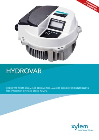
  • 1. HYDROVAR FROM XYLEM HAS BECOME THE NAME OF CHOICE FOR CONTROLLING THE EFFICIENCY OF FIXED SPEED PUMPS. HYDROVAR WELCOMETHE 5TH GENERATION
  • 2. 02 In 1993 HYDROVAR was as the world’s first pump Now the 5th generation h setting a new standard. HYDROVAR 1st generation HYDROVAR 5th generation
  • 3. 03 Typical applications. Domestic/ Industrial Water S upply Fire Fighting Food & Beverage Geothermal Irrigati on / Agricultural Mining / Drainag e /Dewatering W ater Displays / Fou ntains/Features HV AC Municip alWaterSupply established controller. has arrived and is
  • 4. 04 HYDROVAR is an intelligent controller that matches pump performance to demand. It controls the speed of a standard IEC motor by converting the fixed voltage and frequency from the power supply line. It can be fitted easily to any new pump system or retrofitted to existing pumps using the fast and easy “clip and play” mounting clamps. Pump systems are very often oversized for the application and therefore using much more energy than needed. With energy savings of up to 70% at partial loads alone, the typical investment payback period is less than 2 years, depending on energy costs and pump operating times. A motor running at 80% of its maximum speed uses 48% less energy and slashes carbon emissions. The controls available include constant pressure, system curve, constant flow or via an external signal. In addition to these functions HYDROVAR can do things that are normally only performed by the most advanced computerized control systems such as: stopping the pump or pumps at zero demand; stopping the pump or pumps in case of water failure; allowing protection against dry running; a standard feature of a 2nd required input value that allows change over between two different pressure settings via an external switch; sensor failure and over temperature of inverter and motor which protects the pump and motor from under or overvoltage. Other features include: automatic test starts; auto cyclic change of lead and lag pump units; a memory for any inverter fault signals; an operating hours run counter; two levels of password protection if required. What is HYDROVAR capable of? Control for constant pressure Control to match a system curve Control for constant flow Control according to an external signal
  • 5. 05 Available from 1.5 to 22 kW in single or three phase, pump or wall mounted. Pump mounted version will fit on any standard IEC motor. Optismised cooling of the HYDROVAR depending on the power and the speed of the pump is guaranteed by the motor fan. Easy to commission, easy to setup and operate with the easy start up menu allowing you to walk through every step. New features include a larger screen display. No external control panel needed. No water hammer. The steady operation of the pump in partial loads also prevents water hammer, which normally arises in the start/stop operation of full speed pumps. Lower starting current. High current peaks are prevented by adjusting the start ramp times as you can in a soft starter. Multi-pump capability comes as standard which allows control from 1 to 8 pumps. Communicating with a central control system is also possible via an RS485 interface, and each HYDROVAR contains an individual microprocessor which operates independently if a failure occurs. Modbus and BACnet protocol fitted as standard. Lower noise from the pump because of lower speeds during operation. There is less noise in the pipeline and valves because of pump performance to the actual demand, and control along the system curve. Less wear and less mechanical stress because of lower speed of the pumps during operation and no additional load in the starting moment because of the soft start feature. HYDROVAR product overview. Can link up to 8 pumps using HYDROVAR. Multi controller, cascade relay: This is where you can fit one HYDROVAR and up to five slave fixed speed pumps which are switched to on/off on demand. Using this type of system requires a premium card and an external control panel. Inverter InverterInverter Inverter InverterInverter Inverter InverterInverter
  • 6. 06 The 5th generation takes H of robustness, safety, secu Easy and safe accessibility for the wiring harness • Separate wiring chamber with a dedicated cover • All internal electronic components are protected Advanced motor control • Reduced heating of the motor • Extended lifetime of the motor • Due to built-in selectable software protection, motor PTC can be optional • Minimised drive losses Additional features of HYDROVAR: • HYDROVAR can be fitted on any standard IEC motor up to 22 kW. Wall mounting kits are available on request • No separate microprocessor is needed • No separate control panels are needed • No large pressure vessels are needed • No anti-con heaters are needed as these are built in as standard • IP55 • Error logs and real time and date calendar • Quality aluminum body Range extension • The new models are: 1.5kW 3ph 380-460V 1.5kW to 11kW 3ph 208- 240V 3 kW and 4 kW 1ph 208-240V
  • 7. 07 HYDROVARtoanewlevel urity and performance. Easier to commission and to operate • Quick start-up menu allowing faster set-up • Larger LCD display with additional control parameters • 28 languages within the software • Pre-programmed parameter for standard motors HYDROVAR built in protection • Over/under voltage • Overcurrent/output short protection • Low water protection (by using pressure/ flow/float switch) • Sensor failure • Motor over temperature • Inverter over temperature • Minimum threshold/conveyer limit Extended communication capabilities • BACnet and Modbus as standard • Wi-Fi card as an option THDi filter embedded • Will extend the lifetime of equipment • No need for line reactor filters • Better quality of the grid power • Reduced heating of the cables Control offering • Multi-pump capability come as standard from 1-8 pumps • Constant pressure • Constant flow • System curve • Via an 4-20ma or 0-10V external signal • Automatic test and auto change over • It stops at zero demand • Integrated soft start/stop • Complete set of analog and digital input/output • The premium card also allows an additional 2 x inputs and 2 x outputs
  • 8. 08 EcoDesign EN50598-1-2 EN 50598 The Ecodesign directive has been in place since 2011 and introduced minimum requirements for the efficiency of AC motors. These requirements have been gradually intensified. The EN 50598 standard defines efficiency classes for motor systems. EN 50598-1 Integration of the frequency converter and motor into an “extended product” IE – a pump. EN 50598-2 Similar to the IE classification of motors (where all Lowara motors are IE3), EN50598-2 introduces IE classes for frequency converters and IES classes for frequency converters plus motor systems (known as power drive systems). This new regulation was published in early 2015. Classes IE0 – IE2 for frequency converters. Classes IES0 – IES2 for power drive systems (frequency converter plus motor). The EN 50598-2 standard defines efficiency classes from IE0 – IE2 for frequency converters. If a frequency converter has 25% greater losses than the reference value of IE1 then it is classified as IE0; if it has 25% lower losses than the reference value of IE1 then it is classified as IE2. This new standard covers frequency converters that meet the following criteria: - Power rating from 0.12 kW to 1000kW. - Voltage range from 100V to 1000V. Legal requirements In Europe the minimum efficiency performance standards (MEPS) are expected to be at IE1 level in 2018. HYDROVAR is classified as IE2 which is the most efficient in class; this efficiency measure includes the losses due to the built in RFI filters and DC chokes which come as standard up to 22kW in size. When HYDROVAR is connected to a Lowara IE3 motor then the system will achieve the highest IES class – IES2. Ecodesign directive. IE1 IE0 EN 50598-2 IE-classes for frequency converter IE1 = Reference IE2 +25% Reduction -25% Reduction IES1 IES0 EN 50598-2 IES classes for motor-frequency converter systems IES1 = Reference IES2 +20% Reduction -20% Reduction IE1 IE0 EN 50598-2 IE-classes for frequency converter IE1 = Reference IE2 +25% Reduction -25% Reduction IES1 IES0 EN 50598-2 IES classes for motor-frequency converter systems IES1 = Reference IES2 +20% Reduction -20% Reduction
  • 9. 09 Hydrovar fulfills the product standard EN61000-3-2 for single phase and EN61000-3-12 for three phase. Harmonics. HYDROVAR comes with built in Total Harmonic Distortion current filters (THDi) to reduce harmonic interference. In most cases this is sufficient to avoid voltage pollution. Additional harmonic suppression may be required due to grid conditions or when multiple drives are installed. Harmonics are associated with any load that uses a rectifier-based power supply such as radio or TV, computers and lighting ballasts – and other domestic white goods such as washing machines, microwaves and ovens which draw current in a non-sinusoidal fashion. The level of harmonics reflected back to the supply network is usually regulated by the electricity supply utility. Harmonics are voltages and currents in the electrical system at frequencies that are multiples of the fundamental frequency. Generally the greater the amount of installed electronic power switching equipment on site, the greater degree of harmonic distortion. Put simply, harmonics reduce reliability, affect product quality and increase operating costs. EMC. HYDROVAR fulfills the product standard EN61800-3:2004 + A1: 2012 under the 1st Environment which includes domestic premises and buildings/facilities which are directly connected to a low voltage (e.g. 230/400V) mains supply which also supplies buildings used for domestic purposes. HYDROVAR Vector Control (HVC). The HVC automatically and continuously adjusts the output frequency and voltage to optimize the motor operation over a broad range of speeds and loads. For variable torque pump applications, there is no need to de-rate the motor for any operational speed. HVC is superior to the traditional PWM control schemes in the following ways: Full rated motor voltage is provided at rated frequency. The output current wave shape is an almost a perfect sine wave. Automatically chooses motor control for the operating conditions: The low speed switching pattern ensures reliable starts and smooth low speed operation. The high speed switching pattern minimizes switching losses and maximizes drive efficiency. The HVC maximizes the performance and the efficiency of the system while minimized the heating of the motor which results in a longer life. HYDROVAR harmonics and EMC.
  • 10. 10 Automatic Motor Parameter Identification (AMPI). AMPI is an algorithm to measure the electrical motor parameters on a motor at rest. This means that AMPI itself does not supply any torque. AMPI is useful when commissioning systems and optimising the adjustment of the frequency converter to the applied motor. Lowara 2 pole high efficiency IE3 50Hz surface motors have parameters already preset as default.  This feature is particularly used where the default setting does not apply to the connected motor. The benefit of this feature is to maximize the control and efficiency of the HYDROVAR for any given standard asynchronous motor. Motor thermal protection. HYDROVAR has built in software thermal control (STC) so no need for fitting motor PTCs. The STC function is initialized at 1.125 x rated motor current and rated motor frequency. The STC function provides class 20 motor overload protection in accordance with the NEC. Motor thermal protection prevents the motor from overheating. The STC function is an electronic feature that simulates a bimetal relay that is based on internal measurements. The characteristic is shown in the following figure.
  • 11. 11 Optional components. Premium card Card which will allow up to 5 slave pumps and additional analog and 2 x inputs and 2 x outputs Wi-Fi card To connect HYDROVAR via wireless connection Sensors Different sensors are available from pressure, differential, temperature, flow indicator or level sensor Wall mounting kit Stainless steel wall mounting kit fitted with external cooling fan and connection box Fan cowl mounting ring Used for plastic fan cowls, 140mm or 155mm in diameter Motor filters - Motor cables Cable that is ready to connect to the unit and motor
  • 12. 12 Single-speed drives start motors abruptly, subjecting the motor to high torque and current surges up to 10 times the full-load current. In contrast, variable-frequency drives offer a "soft start" capability, gradually ramping up a motor to operating speed. This lessens mechanical and electrical stress on the motor system and can reduce maintenance and repair costs and extend motor life. Other advantages of frequency controllers Lower starting current Reduced mechanical stress Flexibility of operation Reduced noise levels Payback costs in energy and payback Reduced hardware requirements – starters, power factor correction, metering/ monitoring,PI control,etc.no longer required Water consumption in a hotel is not uniform during the day. The pumping system should be able to match the real needs of the users. Benefits. H 0.00 Hours H 24.00H 12.00 H 18.00H 6.00 25 % % of Flow 50 % 75 % 100 % Water usage
  • 13. 13 15% INSTALLATION 10% PURCHASE COST 30% MAINTENANCE 45% OPERATING COSTS << This picture shows the typical LCC of a 15 year life cycle of a pump. Life Cycle Cost (LCC) calculation. As a general guide these figures are realistic, but the percentages could change from job to job, depending on the size / type / and complexity of the installation. The idea here is to give the consultant the perspective that if you save on the energy cost – this makes up a huge part of the LCC, and therefore saving energy will save money. Calculation of LCC = Life Cycle Costs LCC = Cic + Cin + Ce + Co + Cm + Cs + Cd + Cenv Cic Initial costs, purchase price (pump, pipe, valves, auxiliary) Cin Installation and commissioning Ce Energy costs Co Operating costs Cm Maintenance costs Cs Downtime, loss of production Cd Decommissioning Cenv Environmental It’s also important to look at Life Cycle Costs (LCC). Pumping systems account for nearly 20% of the world’s electrical energy usage. Some studies show that between 30 and 50% of energy consumed by a pump could be saved through the use of fitting a VSD. The main economic reasons for using LCC is because companies are becoming increasingly aware of the environmental impacts and looking at energy efficiency as one way of reducing emissions and preserving natural resources. Existing pumping systems provide a greater opportunity for saving money not just by fitting VSDs but looking at installing new pumps which have higher hydraulic efficiencies and also motors which have changed over the years to become more efficient. This is due to the strict EU regulations which have been adopted over the past and coming years to save energy usage.
  • 14. 14 The graph below is an indication of the benefits of fitting HYDROVAR to each fixed speed motor. Please check with your local country government efficiency project schemes; grants may be available towards installing inverter technology on electric motors to achieve substantial energy savings by reducing motor speeds. Energy efficiency funding schemes. Notes: we have based some assumptions on the examples of fitting HYDROVAR onto fixed speed motors: 1. The cost of energy, we have assumed 0.22 euros per kW. 2. We have used two % of the full flow rate being 60% and 80%. 3. We have used 48 weeks per year, 5 days per week, 12 hours per day. 4. We have based an average cost of the HYDROVAR. 5. We have assumed an average installation fitting cost. With all this information we can use an estimated payback for fitting a HYDROVAR VSD in terms of time, money and power saved. HYDROVAR cost savings examples Size of motor for pump unit 3 kW 3 kW 5.5 kW 5.5 kW 11 kW 11 kW 22 kW 22 kW Cost of energy (€) 0.22 0.22 0.22 0.22 0.22 0.22 0.22 0.22 Flow in % of full rated flow 60 80 60 80 60 80 60 80 Weeks per year 48 48 48 48 48 48 48 48 Days per week running 5 5 5 5 5 5 5 5 Hours per day running 12 12 12 12 12 12 12 12 Cost of single HYDROVAR (€) 1,400 1,400 1,700 1,700 2,500 2,500 2,800 2,800 Cost of installation (€) 300 300 300 300 300 300 300 300 Interest rate (%) 3 3 3 3 3 3 3 3 Power used 0.65 kW 1.54 kW 1.19 kW 2.82 kW 2.38 kW 5.63 kW 4.75 kW 11.26 kW Power saved 1.53 kW 1.24 kW 2.80 kW 2.28 kW 5.61 kW 5.56 kW 11.21 kW 9.13kW Money saved in euros per year 968.65 euro's 788.45 euro's 1,775.85 euro's 1,445.50 uro's 3,551.71 euro's 2,890.99 euro's 7,103.42 euro's 5,781.98 euro's Energy saved 4,402.94 kWh 3,583.87 kWh 8,072.06 kWh 6,570.43 kWh 16,144.13 kWh 13.140,86 kWh 32,288.26 kWh 26,281.73 kWh Payback 1.83 years 2.26 years 1.28 years 1.58 years 0.81 years 1 years 0.45 years 0.55 years
  • 15. 15 HYDROVAR start-up screen Start-up menu. START LANGUAGE: SELECTION MOTOR POWER MOTOR SUPPLY PRESET MOTOR PUMP ADDRESS SOFTWARE THERMAL CONTROL (STC OF THE MOTOR) OPERATING MODE: E.G. SERIAL OR SYNCHRONOUS CONSTANT PRESSURE OR CONSTANT DIFFERENTIAL PRESSURE COMMENT: BY DEFAULT SOME PARAMETERS WILL CHANGE (RAMPS, SENSORS, HYSTERESIS ETC…) AFTER 10 MINUTES IF THE START UP IS NOT COMPLETED THE HV WILL DISPLAY A WARNING SHOWING THE CUSTOMER TO COMPLETE IT. DIMENSION UNIT: (BAR, PSI, M3 /H, G/MIN, MH2O, FT,…, %) COMPLETED START UP ? REQUIRED VALUE START VALUE MIN. THRESHOLD DELAY TIME AUTO - START COMPLETED START UP ? SENSOR RANGE PRESSURE TRANSMITER RANGE DATE - TIME (REAL TIME CLOCK / CALENDAR)
  • 16. 16 Energy savings in HVAC systems. Energy is the largest cost of running any pump, with the biggest potential savings. HYDROVAR works with your system to make it efficient. This intelligent variable speed drive controls the pump exactly according to the current requirements of the user. Compared to an unregulated system, HYDROVAR saves up to 70% of the energy consumption (as tested by TÜV Austria, vogw0312-PIR-ZR). The smooth regulation at optimal operation increases not only the efficiency but also the life of the system’s components and reduces maintenance costs.
  • 17. 17 Dimension and weight. Model A Model Type Model Size Maximum Weight 2.015 A 5,6 kg (12.31 lbs) 2.022 A 5,6 kg (12.31 lbs) 3.015 A 5,6 kg (12.31 lbs) 3.022 A 5,6 kg (12.31 lbs) 4.015 A 5,6 kg (12.31 lbs) 4.022 A 5,6 kg (12.31 lbs) 4.030 A 5,6 kg (12.31 lbs) 4.040 A 5,6 kg (12.31 lbs) Model B Model Type Model Size Maximum Weight 2.030 B 10,5 kg (23.14 lbs) 2.040 B 10,5 kg (23.14 lbs) 3.030 B 10,5 kg (23.14 lbs) 3.040 B 10,5 kg (23.14 lbs) 3.055 B 10,5 kg (23.14 lbs) 4.055 B 10,5 kg (23.14 lbs) 4.075 B 10,5 kg (23.14 lbs) 4.110 B 10,5 kg (23.14 lbs) Model C Model Type Model Size Maximum Weight 3.075 C 15,6 kg (34.39 lbs) 3.110 C 15,6 kg (34.39 lbs) 4.150 C 15,6 kg (34.39 lbs) 4.185 C 15,6 kg (34.39 lbs) 4.220 C 15,6 kg (34.39 lbs)
  • 18. 18 Electrical Data. Model Type Rated output Nominal input voltage Model Size Max Input current (A) Efficiency Rated (%) typical Output voltage (V) Max output current (A) Output frequency (Hz) 2.015 1.5 kW 208-240±10% (Single phase) A 11.6 A 94% 0-240 (Three phase) 7.5 A 15-70 (Hz) 2.022 2.2 kW 208-240±10% (Single phase) A 15.1 A 93.5% 0-240 (Three phase) 10 A 15-70 (Hz) 2.030 3 kW 208-240±10% (Single phase) B 22.3 A 93.5% 0-240 (Three phase) 14.3 A 15-70 (Hz) 2.040 4 kW 208-240±10% (Single phase) B 27.6 A 93.5% 0-240 (Three phase) 16.7 A 15-70 (Hz) 3.015 1.5 kW 208-240±10% (Three phase) A 7 A 96% 0-100% of supply voltage 7.5 A 15-70 (Hz) 3.022 2.2 kW 208-240±10% (Three phase) A 9.1 A 96% 0-100% of supply voltage 10 A 15-70 (Hz) 3.030 3 kW 208-240±10% (Three phase) B 13.3 A 96% 0-100% of supply voltage 14.3 A 15-70 (Hz) 3.040 4 kW 208-240±10% (Three phase) B 16.5 A 96% 0-100% of supply voltage 16.7 A 15-70 (Hz) 3.055 5.5 kW 208-240±10% (Three phase) B 23.5 A 96% 0-100% of supply voltage 24.2 A 15-70 (Hz) 3.075 7.5 kW 208-240±10% (Three phase) C 29.6 A 96% 0-100% of supply voltage 31 A 15-70 (Hz) 3.110 11 kW 208-240±10% (Three phase) C 43.9 A 96% 0-100% of supply voltage 44 A 15-70 (Hz) 4.015 1.5 kW 380-460±15% (Three phase) A 3.9 A 96% 0-100% of supply voltage 4.1 A 15-70 (Hz) 4.022 2.2 kW 380-460±15% (Three phase) A 5.3 A 96.5% 0-100% of supply voltage 5.7 A 15-70 (Hz) 4.030 3 kW 380-460±15% (Three phase) A 7.2 A 96.5% 0-100% of supply voltage 7.3 A 15-70 (Hz) 4.040 4 kW 380-460±15% (Three phase) A 10.1 A 96.5% 0-100% of supply voltage 10 A 15-70 (Hz) 4.055 5.5 kW 380-460±15% (Three phase) B 12.8 A 97% 0-100% of supply voltage 13.5 A 15-70 (Hz) 4.075 7.5 kW 380-460±15% (Three phase) B 16.9 A 97% 0-100% of supply voltage 17 A 15-70 (Hz) 4.110 11 kW 380-460±15% (Three phase) B 24.2 A 97% 0-100% of supply voltage 24 A 15-70 (Hz) 4.150 15 kW 380-460±15% (Three phase) C 33.3 A 97% 0-100% of supply voltage 32 A 15-70 (Hz) 4.185 18.5 kW 380-460±15% (Three phase) C 38.1 A 97% 0-100% of supply voltage 38 A 15-70 (Hz) 4.220 22 kW 380-460±15% (Three phase) C 44.7 A 97% 0-100% of supply voltage 44 A 15-70 (Hz)
  • 19. 19 Halve the cost of running a booster set in five steps. Retrofitting. Retrofiitting the ‘plug and play’ HYDROVAR units to a fixed speed booster set not only eliminates the need for a control panel but also introduces a soft start function, that when combined with the benefits of running a pump at a variable speed, can prolong the life of the pump and the water system. By reducing the in-rush current when the pump is turned on, parts such as motor bearings and pipe fittings are protected from hydraulic shock that can cause cavitation and breakdown.
  • 20. 2 Step Two: Clamping the HYDROVAR into place. The HYDROVAR sits directly onto the pump and utilises the cool air emitted from the fan vents to prevent overheating. This means that there is no need for an additional cooling unit, keeping the footprint of the HYDROVAR to a minimum and not utilising valuable wall space. Fixings are located on the outer casing so no need to remove the casing of the HYDROVAR as previous models. Use the four mounting clamps provided together with the central post pin and secure it to the metal fan cowl of the pump unit. The clamps are designed to fit all IEC motors. Stainless steel ring supports are available for motors fitted with plastic fan cowls. Wall mounted versions are available as an option. 1 A E B F C G D H Step One: Assessment of the installation site and the current pump activity. Before any HYDROVAR installation,the site and its current equipment should be assessed to determine the current level of energy being consumed and the kW of the motor.From here,the installer can calculate how much the booster set or heating pump is costing on an annual basis by calculating 0.22 Euros per hour for each kilowatt of energy consumed. An 11kW single pump will therefore cost €2.42 per hour to run at full speed.Once this cost has been multiplied by the number of pumps that are in use,the installer can explain in monetary terms what an average 50 per cent reduction in energy consumption would save the end user. Connecting a HYDROVAR couldn’t be simpler; here we demonstrate an installation in just five steps:
  • 21. 3 Step Three: Pump Terminal Wiring. After attaching the cable glands to the exposed gland plate on the left hand side of the HYDROVAR, unscrew and remove the front of the pump motor terminal box. Take the HYDROVAR connection cables (purchased separately or made using standard wires and connections) and feed the motor terminal end of the cable through the cable entry points, connecting it to the relevant terminals. If you are retrofitting the unit to an existing booster set then the power supply needs to be rerouted directly into the HYDROVAR. No PCT is required and this is now done by the internal software of the HYDROVAR. Once this is done, reattach the terminal front cover, ensuring that the water seal is correctly in place. 4 Step Four: HYDROVAR wiring. Remove the wiring chamber cover and pass the other end of the connection cable through the cable inlet on the left hand side of the HYDROVAR, connecting it to the relevant power supply and signal wires. Once this is done, connect the transducer cable (also called the sensor or pressure transmitter) to the HYDROVAR through the same gland plate. The loose end of the transducer must then be connected to the pipe as close to the pump as possible. 5 Step Five: Completion and programming. After replacing the terminal cover lid of the HYDROVAR unit, programme the required bar pressure using the buttons and the screen. Depending on the number of pumps in the booster set, some very simple programming may be required. This is detailed clearly in the operating instructions manual. The first screen after powering up the unit will be the quick start guide after setting these parameters; the HYDROVAR will automatically begin its soft start and work to the system requirements. 21
  • 23.
  • 24. cod.191007781-P10/16 1) The tissue in plants that brings water upward from the roots; 2) a leading global water technology company. We’re a global team unified in a common purpose: creating innovative solutions to meet our world’s water needs. Developing new technologies that will improve the way water is used, conserved, and re-used in the future is central to our work. We move, treat, analyze, and return water to the environment, and we help people use water efficiently, in their homes, buildings, factories and farms. In more than 150 countries, we have strong, long-standing relationships with customers who know us for our powerful combination of leading product brands and applications expertise, backed by a legacy of innovation. For more information on how Xylem can help you, go to www.xyleminc.com For information and technical support Xylem Service Italia Srl Via Dottor Vittorio Lombardi 14 36075 - Montecchio Maggiore (VI) - Italy Tel. (+39) 0444 707111 Fax (+39) 0444 491043 www.lowara.com Lowara, HYDROVAR, Xylect are trademarks or registered trademarks of Xylem Inc. or one of its subsidiaries. All other trademarks or registered trademarks are property of their respective owners. Xylem Service Italia Srl reserves the right to make modification without prior notice. © 2016 Xylem, Inc. Xylem |’zīl m|e