1. www.nfphampden.com electrical advice transformer theory
1
Transformer Theory
High voltage DC, (Direct Current), transmission lines are the most efficient way to deliver
electrical power over long distances with a minimum of loss to heat. However, before this electricity
can be used, it must be inverted to AC, (Alternating Current), so that it can be transformed to a
manageable voltage. Consequently, most distribution lines are AC voltages.
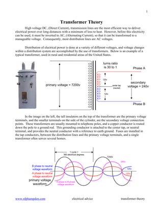
Distribution of electrical power is done at a variety of different voltages, and voltage changes
within a distribution system are accomplished by the use of transformers. Below is an example of a
typical transformer, used in rural and residential areas of the United States.
In the image on the left, the tall insulators on the top of the transformer are the primary voltage
terminals, and the smaller terminals on the side of the cylinder, are the secondary voltage connection
points. These transformers are usually mounted to telephone poles, and a copper conductor is routed
down the pole to a ground rod. This grounding conductor is attached to the center tap, or neutral
terminal, and provides the neutral conductor with a reference to earth ground. Fuses are installed in
the tap conductors, between the distribution lines and the primary voltage terminals, and a single
transformer often serves several homes.
primary voltage = 7200v
secondary
voltage = 240vcenter tap
(neutral)
120v
120v
turns ratio
is 30 to 1 Phase A
Phase B
primary voltage
waveform
A phase to neutral
voltage waveform
B phase to neutral
voltage waveform
A phase to B phase
voltage waveform
1 cycle =
360 electrical degrees
7200v
240v
120v
120v
2. www.nfphampden.com electrical advice transformer theory
2
Neutral (X0)
Typical Delta/Wye
Three Phase Power
Transformer
480v to 120/208v
primary voltage = 480v
secondary
voltage = 120v
turns ratio
is 4 to 1
phase C (X3)
Terminal X0
phase C (H3)
phase B (H2)
primary voltage = 480v
secondary
voltage = 120v
turns ratio
is 4 to 1
phase B (X2)
Terminal X0
phase C (H3)
phase A (H1)
primary voltage = 480v
secondary
voltage = 120v
turns ratio
is 4 to 1
phase A (X1)
Terminal X0
phase B (H2)
phase A (H1)
H3H2
H1
X1
X0
X3 X2
A
B
C
480v
Primary
A B C
N
120/208v
Secondary
3. www.nfphampden.com electrical advice transformer theory
3
The voltage waveforms for the output of the transformer on the previous page look like this;
Industrial and commercial electrical systems differ from residential in a rather significant way.
Three phase power is considerable more complex than single phase, but more efficient in motor
applications, and large area uses. The higher voltages of 277/480v distribution systems are more
efficient, but considerably more dangerous, and should only be maintained and modified by trained
and qualified electricians.
The seemingly odd voltage relationships of 277/480, and 120/208, result from the timing of the
individual output waveforms of the three transformers. In a single phase transformer that is center
tapped and referenced to earth ground to produce a neutral, the line-to-neutral voltages are 180 degrees
out of phase to each other. Therefore, the line-to-line voltage is exactly twice the line-to-neutral value.
Since the line-to-neutral voltage waveforms of a three phase system are 120 degrees out of phase, they
never cross the 0 voltage line at the same time. When two of the waveforms intersect above and below
the 0 voltage line, they are at the exact same potential, and there is no voltage between them.
The B phase to C phase waveform shown in purple is a single phase, 208 volt relationship that
exists in the output from the transformer on the previous page. The waveform produced by the
relationship between A phase and C phase, is very similar to this one, except that it occurs 120
electrical degrees away. Likewise, the waveform for A phase and B phase makes up the third “leg” of
this three phase, 208 volt transformer output.
B phase to neutral
voltage waveform
C phase to neutral
voltage waveform
120v
120v
120v
1 cycle =
360 electrical degrees
A phase to neutral
voltage waveform
B phase to neutral
voltage waveform
C phase to neutral
voltage waveform
208v
120v
120v
1 cycle =
360 electrical degreesB phase to C phase
voltage waveform
0 voltage crossings
4. www.nfphampden.com electrical advice transformer theory
4
The common voltages that exist in the majority of large, commercial and industrial buildings in
the United States are 277/480v, and 120/208v, (60hrz, or cycles per second). In parts of Canada and
some European countries, the common voltage relationship is 220/380v, (50hrz). In each case, the
mathematical relationship between voltages is the same; the larger number is 1.73 times the smaller
number. This relationship is a math function derived from the fact that the waveforms are 120
electrical degrees apart. In the following diagram, the 120/208 could be replaced with 277/480, or
220/380. The change in frequency from 60hrz to 50hrz, simply changes the time it takes for each cycle
of 360 electrical degrees to occur.
At 60hrz, voltage changes direction 120 a second, and at 50hrz, it changes 100 times a second.
This means that the magnetic field around the conductors of these AC circuits is constantly and rapidly
changing. The higher the current the stronger the magnetic field. This constant change in magnetic
flux consumes power and produces heat in what is called hysteresis loss. When the current and
resulting magnetic fields are strong enough, conductors of other systems in close proximity, such as
voice and data transfer circuits, can experience induced voltages that can cause errors and electrical
noise.
Motors, lighting ballasts, and switching power supplies, (typical to computer equipment), all
produce electrical characteristics that can distort the AC waveform. Electrical circuits and devices are
always logical, but sometimes they can be unpredictable, and therefore dangerous, even to qualified
electricians. The best tools are knowledge and understanding.
Whether troubleshooting electrical problems, or making a
new installation, Safety should be the number one concern.
The right tools and test instruments, and the knowledge
to complete the task, are the ingredients for success.
There are countless sources of information that are
available at little or no cost. Safeguard yourself and
everyone that will use the electrical system you install,
by being properly equipped before you begin an electrical
project.
B phase to neutral
voltage waveform
C phase to neutral
voltage waveform
120v
120v
120v
1 cycle =
360 electrical degrees
A phase to neutral
voltage waveform
A phase to C phase
voltage waveform
B phase to C phase
voltage waveform
A phase to B phase
voltage waveform
208v
208v
208v