
Recommended
More Related Content
Similar to Mini Project Report on Gear/Bearing Puller
Similar to Mini Project Report on Gear/Bearing Puller (20)
Recently uploaded
Recently uploaded (20)
Mini Project Report on Gear/Bearing Puller
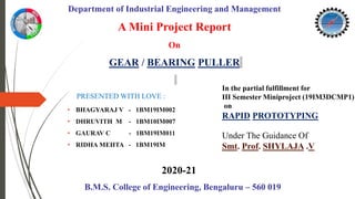
- 1. A Mini Project Report On GEAR / BEARING PULLER PRESENTED WITH LOVE : • BHAGYARAJ V - 1BM19IM002 • DHRUVITH M - 1BM10IM007 • GAURAV C - 1BM19IM011 • RIDHA MEHTA - 1BM19IM In the partial fulfillment for III Semester Miniproject (19IM3DCMP1) on RAPID PROTOTYPING Under The Guidance Of Smt. Prof. SHYLAJA .V Department of Industrial Engineering and Management B.M.S. College of Engineering, Bengaluru – 560 019 2020-21
- 2. RAPID PROTOTYPING - - - Rapid prototyping (RP) is the fabrication of prototype parts directly from a computer solid model without the need for an expensive tool or die set. Rapid prototyping (RP) is the fabrication of prototype parts directly from a computer solid model without the need for an expensive tool or die set. Where the design closely matches the proposed finished product it is said to be a high fidelity prototype, as opposed to a low fidelity prototype, where there is a marked difference between the prototype and the final product.
- 3. Rapid prototyping (RP) includes a variety of manufacturing technologies, although most utilise layered additive manufacturing. However, other technologies used for RP include high-speed machining, casting, moulding and extruding. While additive manufacturing is the most common rapid prototyping process, other more conventional processes can also be used to create prototypes.
- 4. Process include : • Subtractive - whereby a block of material is carved to produce the desired shape using milling, grinding or turning. • Compressive - whereby a semi-solid or liquid material is forced into the desired shape before being solidified, such as with casting, compressive sintering or moulding.
- 5. Different Types of Rapid Prototyping : Stereolithography (SLA) or Vat Photopolymerization - This fast and affordable technique was the first successful method of commercial 3D printing. It uses a bath of photosensitive liquid which is solidified layer-by-layer using a computer-controlled ultra violet (UV) light. Selective Laser Sintering (SLS) - Used for both metal and plastic prototyping, SLS uses a powder bed to build a prototype one layer at a time using a laser to heat and sinter the powdered material. However, the strength of the parts is not as good as with SLA, while the surface of the finished product is usually rough and may require secondary work to finish it.
- 6. Fused Deposition Modelling (FDM) or Material Jetting - This inexpensive, easy-to-use process can be found in most non-industrial desktop 3D printers. It uses a spool of thermoplastic filament which is melted inside a printing nozzle barrel before the resulting liquid plastic is laid down layer-by-layer according to a computer deposition program. Selective Laser Melting (SLM) or Powder Bed Fusion - Often known as powder bed fusion, this process is favoured for making high-strength, complex parts. Selective Laser Melting is frequently used by the aerospace, automotive, defence and medical industries.
- 7. Laminated Object Manufacturing (LOM) or Sheet Lamination - This inexpensive process is less sophisticated than SLM or SLS, but it does not require specially controlled conditions. LOM builds up a series of thin laminates that have been accurately cut with laser beams or another cutting device to create the CAD pattern design. Digital Light Processing (DLP) - Similar to SLA, this technique also uses the polymerisation of resins which are cured using a more conventional light source than with SLA. While faster and cheaper than SLA, DLP often requires the use of support structures and post-build curing.
- 8. Binder Jetting - This technique allows for one or many parts to be printed at one time, although the parts produced are not as strong as those created using SLS. Binder Jetting uses a powder bed onto which nozzles spray micro-fine droplets of a liquid to bond the powder particles together to form a layer of the part.
- 9. Rapid Prototyping Method Used For This Project FDM : (Fused Deposition Modeling) • Fused Deposition Modeling (FDM), or Fused Filament Fabrication (FFF), is an additive manufacturing process that belongs to the material extrusion family. • In FDM, an object is built by selectively depositing melted material in a pre-determined path layer-by-layer. • The materials used are thermoplastic polymers and come in a filament form.
- 10. FDM fabrication process working • A spool of thermoplastic filament is first loaded into the printer • Once the nozzle has reached the desired temperature, the filament is fed to the extrusion head and in the nozzle where it melts. • The extrusion head is attached to a 3-axis system that allows it to move in the X, Y and Z directions. • The melted material is extruded in thin strands and is deposited layer-by-layer in predetermined locations, where it cools and solidifies. • Sometimes the cooling of the material is accelerated through the use of cooling fans attached on the extrusion head.
- 11. • To fill an area, multiple passes are required (similar to coloring a rectangle with a marker). • When a layer is finished, the build platform moves down (or in other machine setups, the extrusion head moves up) and a new layer is deposited. • This process is repeated until the part is complete.
- 12. THE PARAMETERS ARE: • Pressure: 448kPa • Temperature: 190-240 degrees centigrade • Filament Thickness: 1.75 mm(PLA) • Surface Finish: Rough • Build Speed: Low • Material used: ABS, Poly Lactic Acid, Elastomers • Nozzle Size: 0.4mm • Speed in the 1st layer is 40-50mm/s, 80-100mm/s in the second layer and the fastest is 150mm/s
- 13. • Product designers use this process for rapid manufacturing of representative prototype parts. This can aid visualisation, design and development of the manufacturing process ahead of mass production. • Originally, rapid prototyping was used to create parts and scale models for the automotive industry although it has since been taken up by a wide range applications, across multiple industries such as medical and aerospace. • Rapid tooling is another application of RP, whereby a part, such as an injection mould plug or ultrasound sensor wedge, is made and used as a tool in another process. Applications
- 14. • Rapid Prototyping is a very cost effective way to prototype products as it is an automated process, requiring less staff to operate. • This process is also extremely precise, being able to use computer aided design (CAD) to help reduce the amount of material wastage and does not require special tools for prototyping each new product. • Being able to act quickly and solve ay problems also reduces the risk of costly errors during the manufacturing stage. Advantages of Rapid Prototype :-
- 15. Moving to our Mini Project BEARING / GEAR PULLER
- 16. Bearing Pullers Bearing pullers are used to remove parts such as bearings, gears or pulleys from a shaft. They have legs which circle around the back or inside of a part, and a forcing screw which centres up against the end of the shaft.
- 17. As the forcing screw is tightened, the arms pull the part towards the end of the shaft. A bearing puller is used to remove bearings, gears or pulleys, which are components that are in almost constant use. Because of this, they become worn or even damaged and need to be replaced.
- 18. • A bearing is a part of a machine (such as an engine) that compels relative motion. Put simply, this means that a bearing rotates at the same speed as the rotating component; this helps to reduce friction between the moving parts. BEARING • A gear is a wheel containing teeth that work with others to alter the relation between the speed of a driving mechanism (such as the engine of a vehicle) and the speed of the driven parts (the wheels). GEAR
- 19. This is a two legged bearing puller removing a pulley from a shaft.
- 20. BEARING / GEAR PULLER ASSEMBLED VIEW
- 21. VIEW OF EACH PART PULLER JAW
- 22. ROD
- 23. HANDLE
- 24. SPINDER WHEEL
- 25. CARRIER ARM WHEEL
- 26. RIVET
- 28. Why do we need a puller ? If a part, such as a gear, bearing or ball bearing, is so tight that you cannot loosen it with your own strength, you need a tool to help you do so. In a situation where a stuck part is installed on a machine, for example, leading to a standstill, disassembly must be fast as well as efficient, safe and gentle. Only a puller can give you that.
- 29. Pulling with an external puller is the most common type of application and is required when – the part to be pulled off is freely gripped and removed from the outside. A classic external puller consists of a crossbar through which a spindle runs and to which either two or three arms are attached. When pulling, the arms of the external puller grip the part to be pulled off from the outside. By tightening the spindle, the part to be pulled off is released from the shaft. External puller
- 31. Top view
- 33. (any questions ?) • Bhagyaraj V • Dhruvith M • Gaurav C • Ridha Mehta Quick revise : • Rapid prototyping • Fused deposition model • Bearing puller Definition Uses 3d & 2d drawing Applications Printed model • Reference P R E S E N T E D B Y