1. 1. Basic concept for structures with damping devices
Damping devices are intended to consume a portion of the seismic energy input into a
structure. These effects can be explained by the equivalent viscous damping ratio which is
calculated from area of hysteresis loop of dampers.
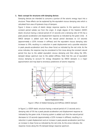
Figure 1 shows a series of elastic design response spectra. In this spectrum, lines of
constant period radiate out from the origin. A single degree of the freedom (SDOF)
elastic structure having a natural period of 1.5 seconds and a damping ratio of 5% has a
peak pseudo-acceleration and displacement response as indicated by the green circle. A
SMCD damper is added such that the natural period decreases to 1.0 seconds
(approximately a 125% increase in stiffness) and the equivalent viscous damping ratio
increases to 30%, resulting in a reduction in peak displacement and a possible reduction
in peak pseudo-acceleration (and thus shear force) as indicated by the red circle. As the
arrow indicates, the response may be considered to first move along the constant natural
period line due to the added equivalent viscous damping and then along the 30%-
damped design spectrum due to the added stiffness. Note that the use of equivalent
viscous damping to account for energy dissipation by SMCD dampers is a major
approximation and may lead to erroneous predictions of seismic response.
Figure 1 Effect of Added Damping and Stiffness (SMCD damper)
In figure 2, a SDOF elastic structure having a natural period of 1.5 seconds and a
damping ratio of 5% has a peak pseudo-acceleration and displacement response as
indicated by the green circle. A bracing system is added such that the natural period
decreases to 1.0 seconds (approximately a 125% increase in stiffness), resulting in a
reduction in peak displacement and an increase in peak pseudo-acceleration (and thus
an increase in shear force) as indicated by the red circle. As the arrow indicates, the
response moves along the 5%-damped design response spectrum.
2. Figure
(a) Deform Shape and Von Mises Stress of SMCD Damper (FEM analysis)
Figure 3 Relation between Shear Force and Deformation
2. Restoring force characteristics and cyclic deformation performance
Figure 3 shows the relation between
section obtained as a result of the
-40
-30
-20
-10
0
10
20
30
40
-15 -10 -5 0 5 10 15
Displacement (mm)
Shearforce(ton)
Figure 2 Effect of Added Stiffness (Traditional Method)
Deform Shape and Von Mises Stress of SMCD Damper (FEM analysis)
(b) Hysteresis Loop of SMCD Damper
Figure 3 Relation between Shear Force and Deformation
Restoring force characteristics and cyclic deformation performance
shows the relation between shear force and lateral deformation
section obtained as a result of the cyclic loading test conducted using
-40
-30
-20
-10
0
10
20
30
40
-15 -10 -5 0 5 10 15
Displacement (mm)
Shearforce(ton)
2 Effect of Added Stiffness (Traditional Method)
Deform Shape and Von Mises Stress of SMCD Damper (FEM analysis)
Figure 3 Relation between Shear Force and Deformation
Restoring force characteristics and cyclic deformation performance of SMCD damper
lateral deformation at the damper
cyclic loading test conducted using wall type SMCD
3. specimen. From this figure, it can be understood that this device shows such stable
elastoplastic behaviors under shear force. It was also confirmed from the experiment that
stable restoring force characteristics can be obtained within the lateral deformation range
of approximately ±10 mm, and that under cyclic loading in constant strain, this damper
allows cyclic deformation performance of more than 20 times.
SMCD damper has a sufficient energy dissipation capacity. After severe earthquake,
SMCD damper should be replaced if necessary.