

More Related Content
Viewers also liked
SSB
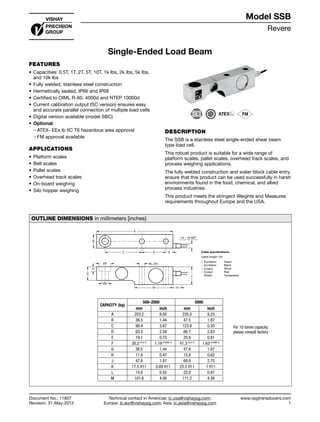
- 1. Revere www.vpgtransducers.com 1 Model SSB Technical contact in Americas: lc.usa@vishaypg.com; Europe: lc.eur@vishaypg.com; Asia: lc.asia@vishaypg.com Document No.: 11807 Revision: 31-May-2012 Single-Ended Load Beam FEATURES • Capacities: 0.5T, 1T, 2T, 5T, 10T, 1k lbs, 2k lbs, 5k lbs, and 10k lbs • Fully welded, stainless steel construction • Hermetically sealed, IP66 and IP68 • Certified to OIML R-60, 4000d and NTEP 10000d • Current calibration output (SC version) ensures easy and accurate parallel connection of multiple load cells • Digital version available (model SBC) • Optional ❍❍ ATEX- EEx ib IIC T6 hazardous area approval ❍❍ FM approval available APPLICATIONS • Platform scales • Belt scales • Pallet scales • Overhead track scales • On-board weighing • Silo hopper weighing DESCRIPTION The SSB is a stainless steel single-ended shear beam type load cell. This robust product is suitable for a wide range of platform scales, pallet scales, overhead track scales, and process weighing applications. The fully welded construction and water block cable entry ensure that this product can be used successfully in harsh environments found in the food, chemical, and allied process industries. This product meets the stringent Weights and Measures requirements throughout Europe and the USA. OUTLINE DIMENSIONS in millimeters [inches} B A C D E 1/4 - 18 NPT J 15M ØK ØL (2x)ØF G H + Excitation Green – Excitation Black + Output White – Output Red Shield Transparent Cable specifications: Cable length: 5m CAPACITY (kg) 500–2000 5000 mm inch mm inch A 203.2 8.00 235.0 9.25 B 36.5 1.44 47.5 1.87 C 98.4 3.87 123.8 0.50 D 63.5 2.50 66.7 2.63 E 19.1 0.75 20.6 0.81 F 30.2+0.2/-0 1.19+0.008/-0 41.3+0.2/-0 1.63+0.008/-0 G 36.5 1.44 47.6 1.87 H 11.9 0.47 15.8 0.62 J 47.6 1.87 69.9 2.75 K 17.5 H11 0.69 H11 25.5 H11 1 H11 L 14.0 0.55 22.0 0.87 M 101.6 4.00 111.2 4.38 Single-Ended Load Beam Document No.: 11807 Revision: 31-May-2012 Model SSB For 10 tonne capacity, please consult factory
- 2. Revere www.vpgtransducers.com 2 Model SSB Technical contact in Americas: lc.usa@vishaypg.com; Europe: lc.eur@vishaypg.com; Asia: lc.asia@vishaypg.com Document No.: 11807 Revision: 31-May-2012 Single-Ended Load Beam SPECIFICATIONS PARAMETER VALUE UNIT Standard capacities (Emax) 0.5, 1, 2, 5 (1) 2, 5 (1) T Accuracy class according to OIML R-60 NTEP III Non- Approved C3 C3MI8 C4 Max. no. of verfication intervals 10000 3000 3000 4000 Min. verification interval (Vmin=Emax/Y) Emax/10000 Emax/15,000 Emax/10000 MDLOR (Z=Emax/2*DR) – 8000 – Min. verification interval, type MR Emax/20000 Emax/20000 Rated output (=S) 2 mV/V Rated output tolerance 0.02 ±mV/V Zero balance 1.0 ±% FSO Combined error 0.0200 0.0500 0.0200 0.0200 0.0170 ±% FSO Non-repeatability 0.0100 0.0200 0.0100 0.0100 0.0090 ±% FSO Minimum dead load output return 0.0250 0.0500 0.0167 0.0063 0.0125 ±% applied load Creep error (30 minutes) 0.0600 0.0245 0.0245 0.0184 ±% applied load Creep error (20 minutes) 0.030 0.0200 0.0053 0.0053 0.0039 ±% applied load Temp. effect on min. dead load output (0.001) 0.0250 0.0070 0.0050 0.0070 ±% FSO/5°C (/°F) Temp. effect on min. dead load output, type MR 0.0035 0.0035 ±% FSO/5°C Temperature effect on sensitivity (0.0008) 0.0250 0.0050 0.0050 0.0045 ±% applied load/ 5°C(/°F) Minimum dead load 0 % Emax Maximum safe over load 150 % Emax Ultimate over load 300 % Emax Maximum safe side load 100 % Emax Deflection at Emax 0.5 max. mm Excitation voltage 5 to 15 V Maximum excitation voltage 18 V Input resistance 350±3.5 Ω Output resistance 350±3 Ω Insulation resistance ≥5000 MΩ Compensated temperature range –10 to +40 °C Operating temperature range –40 to +80 °C Storage temperature range –40 to +90 °C Element material Stainless steel 1.4542 Sealing (DIN 40.050 / EN60.529) IP66 & IP68 SC-Version (current calibration) Standard Recommended torque on fixation bolts 0.5-2T: 110 / 5T: 540 N*m (1) For 10T capacity please consult factory FSO—Full Scale Output SC-version: The rated output and the output resistance are balanced in such a way that the output current is calibrated to within 0.05% of a reference value. This allows easy parallel connection of the load cells. All specifications subject to change without notice.
- 3. Vishay Precision Group Document No.: 63999 Revision: 27-Apr-2011 www.vishaypg.com 1 Legal Disclaimer Notice Disclaimer Legal Disclaimer Notice Disclaimer Document No.: 63999 Revision: 27-Apr-2011 ALL PRODUCTS, PRODUCT SPECIFICATIONS AND DATA ARE SUBJECT TO CHANGE WITHOUT NOTICE. Vishay Precision Group, Inc., its affiliates, agents, and employees, and all persons acting on its or their behalf (collectively, “Vishay Precision Group”), disclaim any and all liability for any errors, inaccuracies or incompleteness contained herein or in any other disclosure relating to any product. The product specifications do not expand or otherwise modify Vishay Precision Group’s terms and conditions of purchase, including but not limited to, the warranty expressed therein. Vishay Precision Group makes no warranty, representation or guarantee other than as set forth in the terms and conditions of purchase. To the maximum extent permitted by applicable law, Vishay Precision Group disclaims (i) any and all liability arising out of the application or use of any product, (ii) any and all liability, including without limitation special, consequential or incidental damages, and (iii) any and all implied warranties, including warranties of fitness for particular purpose, non-infringement and merchantability. Information provided in datasheets and/or specifications may vary from actual results in different applications and performance may vary over time. Statements regarding the suitability of products for certain types of applications are based on Vishay Precision Group’s knowledge of typical requirements that are often placed on Vishay Precision Group products. It is the customer’s responsibility to validate that a particular product with the properties described in the product specification is suitable for use in a particular application. No license, express, implied, or otherwise, to any intellectual property rights is granted by this document, or by any conduct of Vishay Precision Group. The products shown herein are not designed for use in life-saving or life-sustaining applications unless otherwise expressly indicated. Customers using or selling Vishay Precision Group products not expressly indicated for use in such applications do so entirely at their own risk and agree to fully indemnify Vishay Precision Group for any damages arising or resulting from such use or sale. Please contact authorized Vishay Precision Group personnel to obtain written terms and conditions regarding products designed for such applications. Product names and markings noted herein may be trademarks of their respective owners.