

More Related Content
Viewers also liked
Recently uploaded
Recently uploaded (9)
KSR
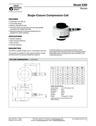
- 1. Revere www.vpgtransducers.com 1 Model KSR Technical contact in Americas: lc.usa@vishaypg.com; Europe: lc.eur@vishaypg.com; Asia: lc.asia@vishaypg.com Document No.: 11840 Revision: 04-Jun-2012 Single-Column Compression Cell FEATURES • Capacities: 6 to 280 ton • Low profile design • Sealing: IP66 (EN 60.529) • Trimmed output ensures easy and accurate parallel connection of multiple load cells • Specially designed mounting arrangements are available for vessel weighing APPLICATIONS • Vessels weighing • High capacity platforms • Tank and silo • Process weighing DESCRIPTION The KSR is a sealed, single column, compression load cell. This product is suitable for high capacity platform scales and level control or process weighing in general. A reliable sealing and mechanical protection of the strain gage area is ensured by the use of stainless steel diaphragms and a housing which are cemented to the measuring element. OUTLINE DIMENSIONS in millimeters F E Ø18 ØD ØC B A B R(2x) 20 Emax 6 13 28 60 130 280 A 56 68 74 90 116 170 B 8 12 14 20 26 45 C 16.7 24.5 36.0 52.7 77.5 114 D 45 55 64 90 121 165 E 52.5 57.5 62.0 75.0 90.5 112.5 F 71.5 76.5 81 94 109.5 131.5 R 50 66 72 100 125 183 Cable specifications Cable length: 10 m (6T version: 5m) Excitation + Red Excitation – White Output + Black Output – Blue Shield Transparent / Yellow Cable screen is not connected to the load cell body. Single-Column Compression Cell Document No.: 11840 Revision: 04-Jun-2012 Model KSR
- 2. Revere www.vpgtransducers.com 2 Model KSR Technical contact in Americas: lc.usa@vishaypg.com; Europe: lc.eur@vishaypg.com; Asia: lc.asia@vishaypg.com Document No.: 11840 Revision: 04-Jun-2012 Single-Column Compression Cell SPECIFICATIONS PARAMETER VALUE UNIT Standard capacities (Emax) 6, 13, 28, 60, 130, 280 ton Accuracy class according to type designation Non-Approved—R2 Non-Approved—R1 Rated output (FSO) 1.5 mV/V Rated output tolerance 0.008 ±mV/V Zero balance 1.5 ±% FSO Combined error 0.200 0.1000 ±% FSO Minimum dead load output return 0.0700 0.0500 ±% FSO Creep error (30 minutes) 0.0800 0.0600 ±% FSO Creep error (20 - 30 minutes) 0.0200 0.0150 ±% FSO Temperature effect on minimum dead load output 0.025 0.025 ±% FSO/5°C Temperature effect on sensitivity 0.2500 0.2500 ±% FSO/5°C Minimum dead load 0 % Emax Maximum safe overload 120 % Emax Ultimate overload 300 % Emax Maximum safe side load 10 % Emax Deflection at Emax 0.35 / 0.53 / 0.80 / 1.22 / 1.85 / 2.67 mm Excitation voltage 5 to 12 V Maximum excitation voltage 15 V Input resistance 275±30 Ω Output resistance 245±0.2 Ω Insulation resistance ≥50 MΩ Compensated temperature range –10 to +40 °C Operating temperature range –20 to +70 °C Storage temperature range –30 to +80 °C Element material (DIN) Tool steel Finish Epoxy painting Sealing (DIN 40.050 / EN60.529) IP66 FSO—Full Scale Output Mounting: Correct mounting of the load cells is essential to ensure optimum accuracy and performance. Further information is available upon request. All specifications subject to change without notice.
- 3. Vishay Precision Group Document No.: 63999 Revision: 27-Apr-2011 www.vishaypg.com 1 Legal Disclaimer Notice Disclaimer Legal Disclaimer Notice Disclaimer Document No.: 63999 Revision: 27-Apr-2011 ALL PRODUCTS, PRODUCT SPECIFICATIONS AND DATA ARE SUBJECT TO CHANGE WITHOUT NOTICE. Vishay Precision Group, Inc., its affiliates, agents, and employees, and all persons acting on its or their behalf (collectively, “Vishay Precision Group”), disclaim any and all liability for any errors, inaccuracies or incompleteness contained herein or in any other disclosure relating to any product. The product specifications do not expand or otherwise modify Vishay Precision Group’s terms and conditions of purchase, including but not limited to, the warranty expressed therein. Vishay Precision Group makes no warranty, representation or guarantee other than as set forth in the terms and conditions of purchase. To the maximum extent permitted by applicable law, Vishay Precision Group disclaims (i) any and all liability arising out of the application or use of any product, (ii) any and all liability, including without limitation special, consequential or incidental damages, and (iii) any and all implied warranties, including warranties of fitness for particular purpose, non-infringement and merchantability. Information provided in datasheets and/or specifications may vary from actual results in different applications and performance may vary over time. Statements regarding the suitability of products for certain types of applications are based on Vishay Precision Group’s knowledge of typical requirements that are often placed on Vishay Precision Group products. It is the customer’s responsibility to validate that a particular product with the properties described in the product specification is suitable for use in a particular application. No license, express, implied, or otherwise, to any intellectual property rights is granted by this document, or by any conduct of Vishay Precision Group. The products shown herein are not designed for use in life-saving or life-sustaining applications unless otherwise expressly indicated. Customers using or selling Vishay Precision Group products not expressly indicated for use in such applications do so entirely at their own risk and agree to fully indemnify Vishay Precision Group for any damages arising or resulting from such use or sale. Please contact authorized Vishay Precision Group personnel to obtain written terms and conditions regarding products designed for such applications. Product names and markings noted herein may be trademarks of their respective owners.