Load Cell Technical Specifications
•
0 likes•133 views

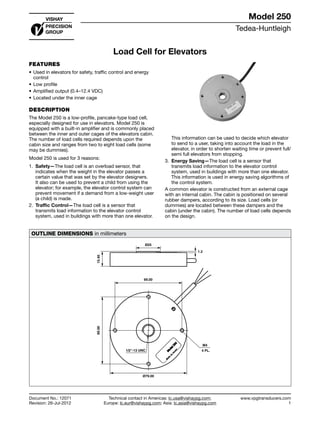
The document describes the Tedea-Huntleigh Model 250 load cell, which is used in elevators for safety, traffic control, and energy saving purposes. It is a low-profile, pancake-type load cell with a built-in amplifier that is commonly placed between the inner and outer elevator cages. The load cell senses the weight in the elevator and transmits this information to the control system. It is used as an overload sensor for safety, to determine which elevator to send for traffic control, and to provide information to energy saving algorithms in the control system.

More Related Content
What's hot
Viewers also liked
Load Cell Technical Specifications
- 1. Tedea-Huntleigh www.vpgtransducers.com 1 Model 250 Technical contact in Americas: lc.usa@vishaypg.com; Europe: lc.eur@vishaypg.com; Asia: lc.asia@vishaypg.com Document No.: 12071 Revision: 26-Jul-2012 Load Cell for Elevators FEATURES • Used in elevators for safety, traffic control and energy control • Low profile • Amplified output (0.4–12.4 VDC) • Located under the inner cage DESCRIPTION The Model 250 is a low-profile, pancake-type load cell, especially designed for use in elevators. Model 250 is equipped with a built-in amplifier and is commonly placed between the inner and outer cages of the elevators cabin. The number of load cells required depends upon the cabin size and ranges from two to eight load cells (some may be dummies). Model 250 is used for 3 reasons: 1. Safety—The load cell is an overload sensor, that indicates when the weight in the elevator passes a certain value that was set by the elevator designers. It also can be used to prevent a child from using the elevator; for example, the elevator control system can prevent movement if a demand from a low-weight user (a child) is made. 2. Traffic Control—The load cell is a sensor that transmits load information to the elevator control system, used in buildings with more than one elevator. This information can be used to decide which elevator to send to a user, taking into account the load in the elevator, in order to shorten waiting time or prevent full/ semi full elevators from stopping. 3. Energy Saving—The load cell is a sensor that transmits load information to the elevator control system, used in buildings with more than one elevator. This information is used in energy saving algorithms of the control system. A common elevator is constructed from an external cage with an internal cabin. The cabin is positioned on several rubber dampers, according to its size. Load cells (or dummies) are located between these dampers and the cabin (under the cabin). The number of load cells depends on the design. OUTLINE DIMENSIONS in millimeters Ø79.00 69.00 69.00 1/2"-13 UNC M4 15.40 4 PL. Ø25 1.2 Load Cell for Elevators Document No.: 12071 Revision: 26-Jul-2012 Model 250
- 2. Tedea-Huntleigh www.vpgtransducers.com 2 Model 250 Technical contact in Americas: lc.usa@vishaypg.com; Europe: lc.eur@vishaypg.com; Asia: lc.asia@vishaypg.com Document No.: 12071 Revision: 26-Jul-2012 Load Cell for Elevators SPECIFICATIONS PARAMETER VALUE UNIT Rated capacity—R.C. 500 kg Rated output—R.O. 24 mV/kg Rated output tolerance 0.24 ±mV/kg Zero balance 0–0.5 V Total error 5 ±% of R.O. Temperature range, safe –30 to +70 °C Maximum safe static overload 200* % of R.C. Ultimate static overload 300 % of R.C. Excitation, recommended 24 VDC regulated Excitation, minimum 8 VDC Excitation, maximum 28 VDC Current consumption 30 mA Insulation resistance >2000 MΩ Construction Alloy steel yellow zinc plated Environmental protection IP65 Color code Red: +Exc, Black: Com, White: Out Cable length 5 m * Amplifier is saturated at 500 kg All specifications subject to change without notice.
- 3. Vishay Precision Group, Inc. www.vpgsensors.com 1 Legal Disclaimer Notice Document No.: 63999 Revision: 15-Jul-2014 Disclaimer ALL PRODUCTS, PRODUCT SPECIFICATIONS AND DATA ARE SUBJECT TO CHANGE WITHOUT NOTICE. Vishay Precision Group, Inc., its affiliates, agents, and employees, and all persons acting on its or their behalf (collectively, “VPG”), disclaim any and all liability for any errors, inaccuracies or incompleteness contained herein or in any other disclosure relating to any product. The product specifications do not expand or otherwise modify VPG’s terms and conditions of purchase, including but not limited to, the warranty expressed therein. VPG makes no warranty, representation or guarantee other than as set forth in the terms and conditions of purchase. To the maximum extent permitted by applicable law, VPG disclaims (i) any and all liability arising out of the application or use of any product, (ii) any and all liability, including without limitation special, consequential or incidental damages, and (iii) any and all implied warranties, including warranties of fitness for particular purpose, non-infringement and merchantability. Information provided in datasheets and/or specifications may vary from actual results in different applications and performance may vary over time. Statements regarding the suitability of products for certain types of applications are based on VPG’s knowledge of typical requirements that are often placed on VPG products. It is the customer’s responsibility to validate that a particular product with the properties described in the product specification is suitable for use in a particular application. You should ensure you have the current version of the relevant information by contacting VPG prior to performing installation or use of the product, such as on our website at vpgsensors.com. No license, express, implied, or otherwise, to any intellectual property rights is granted by this document, or by any conduct of VPG. The products shown herein are not designed for use in life-saving or life-sustaining applications unless otherwise expressly indicated. Customers using or selling VPG products not expressly indicated for use in such applications do so entirely at their own risk and agree to fully indemnify VPG for any damages arising or resulting from such use or sale. Please contact authorized VPG personnel to obtain written terms and conditions regarding products designed for such applications. Product names and markings noted herein may be trademarks of their respective owners. Copyright Vishay Precision Group, Inc., 2014. All rights reserved. Disclaimer Legal Disclaimer Notice