SlideShare a Scribd company logo
1 of 3
Download to read offline
Technical contact: vpgt.americas@vpgsensors.com,
vpgt.asia@vpgsensors.com, and vpgt.emea@vpgsensors.com
Tedea-Huntleigh
www.vpgtransducers.com
1
Model CellMate
Document No.: 12072
Revision: 20 Dec 2014
Load Cell Mounting Assembly for Models 355, 3410, 3420 and 3510Load Cell Mounting Assembly for Models 355, 3410, 3420 and 3510
A perfect solution to vessel weighing in diaries, chemical,
bottling, and food processing plants, stainless steel
CellMateTM
mounts can be used on tanks, silos, and many
other weighing vessels and applications.
The CellMateTM
family of mountings also provides an
unparalleled degree of protection for load cells and
maintains a permanent load cell safety system, reducing
load cell damage and plant down-time.
CellMateTM
assemblies are available in three models with
weighing capacities from 5 to 5000 kg in stainless steel.
Standard dimensions and hole sizes provide for fast and
easy placement of load cells. Ideal for use with
Tedea-Huntleigh’s line of hermetically sealed shear and
bending beam load cells. CellMateTM
includes an internal
jack which enables users to install the fittings on silos or
tanks with or without load cells.
OUTLINE DIMENSIONS in millimeters
80
VIEW A
A
INJACKEDUPPOSITION
FORLOADCELLREMOVAL
86
2 SLOTS MILLED Ø11 WIDE IN BASE PLATE
FOR M10 UNC FIXING BOLTS
2 HOLES DRILLED Ø11 WIDE IN BASE PLATE
FOR M10 FIXING BOLTS
56
18 1424
96
1313
70
2HOLESTRAPPED
Ø11IN
CAPPLATEFOR
M12BOLTS
ORM10
THROUGHBOLTS
42 76 64
132
25
INWEIGHINGPOSITION
Model 355
(5–500 kg)
78MIN
CLEARANCEFOR
LOADCELLREMOVAL
FEATURES
•	Simplifies load cell installation on tanks, silos, and other
weighing vessels
•	3 models suitable for load cell Models 3510, 3410,
3420, and 355
•	Accepts load cells ranging in capacity from 5 to 5,000 kg
•	Permanent protection against load cell damage
•	Grounding strap provides low resistance path to
minimize electrical potentials
•	Provision for thermal expansion, contraction and lift-off
due to winds or collision
•	Cable gland protector prevents cable damage
•	Stainless steel construction
•	Internal jack for load cell easy installation and replacing
•	Ball and cup version also available
APPLICATIONS
•	Hostile environments applications
•	Process control
•	Batch weighing
•	Silo/hopper weighing
•	Belt scale weighing
DESCRIPTION
The CellMateTM
is a superior load cell mounting assembly
that dramatically simplifies load cell installation.
Technical contact: vpgt.americas@vpgsensors.com,
vpgt.asia@vpgsensors.com, and vpgt.emea@vpgsensors.com
Tedea-Huntleigh
www.vpgtransducers.com
2
Model CellMate
Document No.: 12072
Revision: 20 Dec 2014
Load Cell Mounting Assembly for Models 355, 3410, 3420 and 3510
OUTLINE DIMENSIONS in millimeters
JACKEDUPFOR
LOADCELLREMOVAL
108
100
VIEW A
106MIN
CLEARANCEFOR
3410LOAD
CELLREMOVAL
INWEIGHINGPOSITION
A
3410 3510
111MIN
CLEARANCEFOR
3510LOADCELLREMOVAL
2 X 3/4" - 10 HOLES IN CAP
PLATE FOR 3/4" UNC BOLTS
OR 5/8" THROUGH BOLTS
2 SLOTS MILLED 0.78" WIDE IN BASE
PLATE FOR 3/4" FIXING BOLTS
2 x 0.78" DIA: THRU HOLES IN BASE
PLATE FOR 3/4" FIXING BOLTS
3015
max. 81
110
2020
70
2015 130
165
30
Model 3410/3411
(1,000–4,000 lbs)
(250–2,000 kg)
Model 3510
(300–2,000 kg)
135
INWEIGHINGPOSITION
VIEW A
3420 3510
Model 3420/3421
(5,000–10,000 lbs)
Model 3510
(3000 and 5,000 kg)
A
2 SLOTS MILLED 0.78" WIDE IN BASE
PLATE FOR 3/4" FIXING BOLTS
2 HOLES DRILLED 0.78" BASE
PLATE FOR 3/4" FIXING BOLTS
3520
91
36
153
31.531.5
90
16220 34
216
47
40
140
JACKEDUPFOR
LOADCELLREMOVAL
159MIN
CLEARANCEFOR
3420LOAD
CELLREMOVAL
143
Vishay Precision Group, Inc.
www.vpgsensors.com
1
Legal Disclaimer Notice
Document No.: 63999
Revision: 15-Jul-2014
Disclaimer
ALL PRODUCTS, PRODUCT SPECIFICATIONS AND DATA ARE SUBJECT TO CHANGE WITHOUT NOTICE.
Vishay Precision Group, Inc., its affiliates, agents, and employees, and all persons acting on its or their behalf
(collectively, “VPG”), disclaim any and all liability for any errors, inaccuracies or incompleteness contained herein or in
any other disclosure relating to any product.
The product specifications do not expand or otherwise modify VPG’s terms and conditions of purchase, including but
not limited to, the warranty expressed therein.
VPG makes no warranty, representation or guarantee other than as set forth in the terms and conditions of purchase.
To the maximum extent permitted by applicable law, VPG disclaims (i) any and all liability arising out of the
application or use of any product, (ii) any and all liability, including without limitation special, consequential or
incidental damages, and (iii) any and all implied warranties, including warranties of fitness for particular purpose,
non-infringement and merchantability.
Information provided in datasheets and/or specifications may vary from actual results in different applications and
performance may vary over time. Statements regarding the suitability of products for certain types of applications
are based on VPG’s knowledge of typical requirements that are often placed on VPG products. It is the customer’s
responsibility to validate that a particular product with the properties described in the product specification is suitable for
use in a particular application. You should ensure you have the current version of the relevant information by contacting
VPG prior to performing installation or use of the product, such as on our website at vpgsensors.com.
No license, express, implied, or otherwise, to any intellectual property rights is granted by this document, or by any
conduct of VPG.
The products shown herein are not designed for use in life-saving or life-sustaining applications unless otherwise
expressly indicated. Customers using or selling VPG products not expressly indicated for use in such applications do
so entirely at their own risk and agree to fully indemnify VPG for any damages arising or resulting from such use or sale.
Please contact authorized VPG personnel to obtain written terms and conditions regarding products designed for such
applications.
Product names and markings noted herein may be trademarks of their respective owners.
Copyright Vishay Precision Group, Inc., 2014. All rights reserved.
Disclaimer
Legal Disclaimer Notice

More Related Content

What's hot (20)

65016-TWA
65016-TWA65016-TWA
65016-TWA
 
9123
91239123
9123
 
65058S
65058S65058S
65058S
 
9803
98039803
9803
 
614
614614
614
 
65083
6508365083
65083
 
1142
11421142
1142
 
A new-method-for-testing-electrolytic-capacitors-to-compare-life-expectancy
A new-method-for-testing-electrolytic-capacitors-to-compare-life-expectancyA new-method-for-testing-electrolytic-capacitors-to-compare-life-expectancy
A new-method-for-testing-electrolytic-capacitors-to-compare-life-expectancy
 
CSP-M
CSP-MCSP-M
CSP-M
 
60048
6004860048
60048
 
9303
93039303
9303
 
Testing/Manufacture/Bennewart Flex Tester
Testing/Manufacture/Bennewart Flex TesterTesting/Manufacture/Bennewart Flex Tester
Testing/Manufacture/Bennewart Flex Tester
 
Testing/Manufacture/Bennewert flex tester
Testing/Manufacture/Bennewert flex testerTesting/Manufacture/Bennewert flex tester
Testing/Manufacture/Bennewert flex tester
 
3510
35103510
3510
 
220
220220
220
 
121
121121
121
 
65088
6508865088
65088
 
93006
9300693006
93006
 
250
250250
250
 
60051
6005160051
60051
 

Viewers also liked (16)

CHAFING DISH
CHAFING DISHCHAFING DISH
CHAFING DISH
 
620
620620
620
 
TORCH, BURNER & GAS
TORCH, BURNER & GASTORCH, BURNER & GAS
TORCH, BURNER & GAS
 
1030
10301030
1030
 
65083H
65083H65083H
65083H
 
65040
6504065040
65040
 
65114
6511465114
65114
 
1002
10021002
1002
 
1040 1041
1040 10411040 1041
1040 1041
 
EHP & ZEMIC LEVELING FOOT
EHP & ZEMIC LEVELING FOOTEHP & ZEMIC LEVELING FOOT
EHP & ZEMIC LEVELING FOOT
 
327
327327
327
 
1260
12601260
1260
 
3520
35203520
3520
 
1430
14301430
1430
 
PLASTIC BEVERAGE WARES & BOWL
PLASTIC BEVERAGE WARES & BOWLPLASTIC BEVERAGE WARES & BOWL
PLASTIC BEVERAGE WARES & BOWL
 
1330
13301330
1330
 

Similar to VPG Load Cell Mounting (19)

220-10T WEIGHBRIDGE MOUNT
220-10T WEIGHBRIDGE MOUNT220-10T WEIGHBRIDGE MOUNT
220-10T WEIGHBRIDGE MOUNT
 
220-5T
220-5T220-5T
220-5T
 
220-30-50T WEIGHBRIDGE MOUNT
220-30-50T WEIGHBRIDGE MOUNT220-30-50T WEIGHBRIDGE MOUNT
220-30-50T WEIGHBRIDGE MOUNT
 
3410/3411
3410/34113410/3411
3410/3411
 
4158 SILO MOUNT
4158 SILO MOUNT4158 SILO MOUNT
4158 SILO MOUNT
 
380
380380
380
 
9123/5123 MOUNT
9123/5123 MOUNT9123/5123 MOUNT
9123/5123 MOUNT
 
5303
53035303
5303
 
1006
10061006
1006
 
1033
10331033
1033
 
3310
33103310
3310
 
355
355355
355
 
91002
9100291002
91002
 
MBB
MBBMBB
MBB
 
220 ROCKER PIN MOUNT
220 ROCKER PIN MOUNT220 ROCKER PIN MOUNT
220 ROCKER PIN MOUNT
 
ASC/DSC SELF-ALIGNING SET
ASC/DSC SELF-ALIGNING SETASC/DSC SELF-ALIGNING SET
ASC/DSC SELF-ALIGNING SET
 
220 SILO MOUNT
220 SILO MOUNT 220 SILO MOUNT
220 SILO MOUNT
 
240
240240
240
 
HOC
HOCHOC
HOC
 

VPG Load Cell Mounting

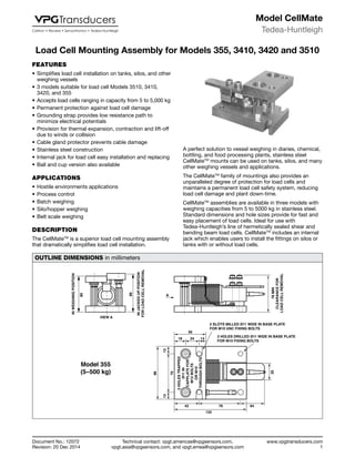
  • 1. Technical contact: vpgt.americas@vpgsensors.com, vpgt.asia@vpgsensors.com, and vpgt.emea@vpgsensors.com Tedea-Huntleigh www.vpgtransducers.com 1 Model CellMate Document No.: 12072 Revision: 20 Dec 2014 Load Cell Mounting Assembly for Models 355, 3410, 3420 and 3510Load Cell Mounting Assembly for Models 355, 3410, 3420 and 3510 A perfect solution to vessel weighing in diaries, chemical, bottling, and food processing plants, stainless steel CellMateTM mounts can be used on tanks, silos, and many other weighing vessels and applications. The CellMateTM family of mountings also provides an unparalleled degree of protection for load cells and maintains a permanent load cell safety system, reducing load cell damage and plant down-time. CellMateTM assemblies are available in three models with weighing capacities from 5 to 5000 kg in stainless steel. Standard dimensions and hole sizes provide for fast and easy placement of load cells. Ideal for use with Tedea-Huntleigh’s line of hermetically sealed shear and bending beam load cells. CellMateTM includes an internal jack which enables users to install the fittings on silos or tanks with or without load cells. OUTLINE DIMENSIONS in millimeters 80 VIEW A A INJACKEDUPPOSITION FORLOADCELLREMOVAL 86 2 SLOTS MILLED Ø11 WIDE IN BASE PLATE FOR M10 UNC FIXING BOLTS 2 HOLES DRILLED Ø11 WIDE IN BASE PLATE FOR M10 FIXING BOLTS 56 18 1424 96 1313 70 2HOLESTRAPPED Ø11IN CAPPLATEFOR M12BOLTS ORM10 THROUGHBOLTS 42 76 64 132 25 INWEIGHINGPOSITION Model 355 (5–500 kg) 78MIN CLEARANCEFOR LOADCELLREMOVAL FEATURES • Simplifies load cell installation on tanks, silos, and other weighing vessels • 3 models suitable for load cell Models 3510, 3410, 3420, and 355 • Accepts load cells ranging in capacity from 5 to 5,000 kg • Permanent protection against load cell damage • Grounding strap provides low resistance path to minimize electrical potentials • Provision for thermal expansion, contraction and lift-off due to winds or collision • Cable gland protector prevents cable damage • Stainless steel construction • Internal jack for load cell easy installation and replacing • Ball and cup version also available APPLICATIONS • Hostile environments applications • Process control • Batch weighing • Silo/hopper weighing • Belt scale weighing DESCRIPTION The CellMateTM is a superior load cell mounting assembly that dramatically simplifies load cell installation.
  • 2. Technical contact: vpgt.americas@vpgsensors.com, vpgt.asia@vpgsensors.com, and vpgt.emea@vpgsensors.com Tedea-Huntleigh www.vpgtransducers.com 2 Model CellMate Document No.: 12072 Revision: 20 Dec 2014 Load Cell Mounting Assembly for Models 355, 3410, 3420 and 3510 OUTLINE DIMENSIONS in millimeters JACKEDUPFOR LOADCELLREMOVAL 108 100 VIEW A 106MIN CLEARANCEFOR 3410LOAD CELLREMOVAL INWEIGHINGPOSITION A 3410 3510 111MIN CLEARANCEFOR 3510LOADCELLREMOVAL 2 X 3/4" - 10 HOLES IN CAP PLATE FOR 3/4" UNC BOLTS OR 5/8" THROUGH BOLTS 2 SLOTS MILLED 0.78" WIDE IN BASE PLATE FOR 3/4" FIXING BOLTS 2 x 0.78" DIA: THRU HOLES IN BASE PLATE FOR 3/4" FIXING BOLTS 3015 max. 81 110 2020 70 2015 130 165 30 Model 3410/3411 (1,000–4,000 lbs) (250–2,000 kg) Model 3510 (300–2,000 kg) 135 INWEIGHINGPOSITION VIEW A 3420 3510 Model 3420/3421 (5,000–10,000 lbs) Model 3510 (3000 and 5,000 kg) A 2 SLOTS MILLED 0.78" WIDE IN BASE PLATE FOR 3/4" FIXING BOLTS 2 HOLES DRILLED 0.78" BASE PLATE FOR 3/4" FIXING BOLTS 3520 91 36 153 31.531.5 90 16220 34 216 47 40 140 JACKEDUPFOR LOADCELLREMOVAL 159MIN CLEARANCEFOR 3420LOAD CELLREMOVAL 143
  • 3. Vishay Precision Group, Inc. www.vpgsensors.com 1 Legal Disclaimer Notice Document No.: 63999 Revision: 15-Jul-2014 Disclaimer ALL PRODUCTS, PRODUCT SPECIFICATIONS AND DATA ARE SUBJECT TO CHANGE WITHOUT NOTICE. Vishay Precision Group, Inc., its affiliates, agents, and employees, and all persons acting on its or their behalf (collectively, “VPG”), disclaim any and all liability for any errors, inaccuracies or incompleteness contained herein or in any other disclosure relating to any product. The product specifications do not expand or otherwise modify VPG’s terms and conditions of purchase, including but not limited to, the warranty expressed therein. VPG makes no warranty, representation or guarantee other than as set forth in the terms and conditions of purchase. To the maximum extent permitted by applicable law, VPG disclaims (i) any and all liability arising out of the application or use of any product, (ii) any and all liability, including without limitation special, consequential or incidental damages, and (iii) any and all implied warranties, including warranties of fitness for particular purpose, non-infringement and merchantability. Information provided in datasheets and/or specifications may vary from actual results in different applications and performance may vary over time. Statements regarding the suitability of products for certain types of applications are based on VPG’s knowledge of typical requirements that are often placed on VPG products. It is the customer’s responsibility to validate that a particular product with the properties described in the product specification is suitable for use in a particular application. You should ensure you have the current version of the relevant information by contacting VPG prior to performing installation or use of the product, such as on our website at vpgsensors.com. No license, express, implied, or otherwise, to any intellectual property rights is granted by this document, or by any conduct of VPG. The products shown herein are not designed for use in life-saving or life-sustaining applications unless otherwise expressly indicated. Customers using or selling VPG products not expressly indicated for use in such applications do so entirely at their own risk and agree to fully indemnify VPG for any damages arising or resulting from such use or sale. Please contact authorized VPG personnel to obtain written terms and conditions regarding products designed for such applications. Product names and markings noted herein may be trademarks of their respective owners. Copyright Vishay Precision Group, Inc., 2014. All rights reserved. Disclaimer Legal Disclaimer Notice