1. 1 Gearheads
CSG-GH Gearhead Series
High-PerformanceGearheadforServomotors
High-PerformanceGearheadforServomotors
CSG-GHSeries
CSG-GHSeries
High-PerformanceGearheadforServomotors
High-PerformanceGearheadforServomotors
CSF-GHSeries
CSF-GHSeries
ØC
Size
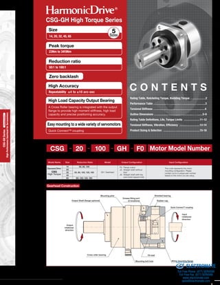
14, 20, 32, 45, 65 Sizes
5
Zero backlash
High Accuracy
Repeatability ±4 to ±10 arc-sec
Quick Connect™ coupling
A Cross Roller bearing is integrated with the output
flange to provide high moment stiffness, high load
capacity and precise positioning accuracy.
Figure 039-1
CSG-GH High Torque Series
cket
: mm) Table 039-1
Gearhead Construction
Figure 066-1
(The figure indicates output shaft type.)
Mounting pilot
Grease filling port
(2 locations)Output Shaft (flange optional)
Output
rotational
direction
Oil sealCross roller bearing
Mounting bolt hole Motor mounting flange
Input
rotational
direction
Shielded bearing
Rubber cap
Quick Connect™ coupling
C O N T E N T S
Rating Table, Ratcheting Torque, Buckling Torque …..............2
Performance Table …............…............…............….........3
Torsional Stiffness …............…........................................4
Outline Dimensions …..........................…............….......5-9
Rating Table Definitions, Life, Torque Limits ..................11-12
Torsional Stiffness, Vibration, Efficiency .......................13-14
Product Sizing & Selection ............…..........................15-16
e manufacturing
tolerances not
is optional.
CSG
Reduction RatioSizeModel Name
CSG
High Torque
Output Configuration Input Configuration
14
20
32
45
65
50, 80, 100
50, 80, 100, 120, 160
80, 100, 120, 160
Model
GH:Gearhead
20 100 GH F0- - - -
F0: Flange output
J2: Straight shaft (without
key)
J6: Straight shaft (with key
and center tapped hole)
This code represents the motor
mounting configuration. Please
contact us for a unique part number
based on the motor you are using.
Motor Model Number
Peak torque
23Nm to 3419Nm
Reduction ratio
50:1 to 160:1
High Load Capacity Output Bearing
Easy mounting to a wide variety of servomotors
Mass (kg) *2
Shaft
48.0 38.0
Flange
52.0 42.0
n above are not
4-D*3
Table 039-2
50
9
-
(Unit: mm)
kgm2)
ELECTROMATE
Toll Free Phone (877) SERVO98
Toll Free Fax (877) SERV099
www.electromate.com
sales@electromate.com
Sold & Serviced By:
2. 2Gearheads
CSG-GH Gearhead Series
High-PerformanceGearheadforServomotors
High-PerformanceGearheadforServomotors
CSG-GHSeries
CSG-GHSeries
*1: A
m
1
2
3
4
6
θer
Size 14 20 32 45 65
All Ratios 260 800 3500 8900 26600
Rating Table CSG-GH P
Ratcheting Torque CSG-GH
Buckling Torque CSG-GH
Table 067-2
Reduction ratio
Size
14 20 32 45 65
50
80
100
120
160
110
140
100
—
—
280
450
330
310
280
1200
1800
1300
1200
1200
3500
5000
4000
3600
3300
—
14000
12000
10000
10000
(Unit: Nm)
Table 067-3(Unit: Nm)
CSG-GH Gearhead Series
042
High-performanceGearHeadsforServoMotorsseries
HPGPseries
High-performanceGearHeadsforServoMotorsseries
HPGseries
High-performanceGearHeadsforServoMotorsseries
CSG-GHseries
High-performanceGearHeadsforServoMotorsseries
CSF-GHseries
High-performanceGearHeadsforServoMotorsseries
HPGseries(OrthogonalShaftType)
*1: Rated torque is based on L10 life of 7,000 hours when input speed is 2000 rpm
*2: Rated torque is based on L10 life of 7,000 hours when input speed is 3000 rpm, input rotational speed for size 65 is 2800 rpm.
*3: Maximum value of average load torque is based on the load torque pattern. Note that exceeding this value may deteriorate the life or durability of the product.
*4: The limit for torque during start and stop cycles.
*5: The limit for torque during emergency stops or from external shock loads. Always operate below this value. Calculate the number of permissible events to ensure
it meets required operating conditions.
*6: Maximum average input speed is limited by heat generation in the speed reducer assuming a continuous operating speed or the average input speed of a motion
profile. The actual limit for average input speed depends on the operating environment.
*7: Maximum instantaneous input speed.
*8: The mass is for the gearhead only (without input shaft coupling & motor flange). Please contact us for the mass of your specific configuration.
*9: See page 86 for more information about Torque ratings.
S
*2: Th
se
po
ca
Me
va
Table 067-1
14
20
32
45
65
3500
3500
3500
3000
1900
8500
6500
4800
3800
2800
0.62
1.8
4.6
13
32
0.50
1.4
3.2
10
24
50
80
100
50
80
100
120
160
50
80
100
120
160
50
80
100
120
160
80
100
120
160
7.0
10
10
33
44
52
52
52
99
153
178
178
178
229
407
459
523
523
969
1236
1236
1236
23
30
36
73
96
107
113
120
281
395
433
459
484
650
918
982
1070
1147
2743
2990
3263
3419
46
61
70
127
165
191
191
191
497
738
812
812
812
1235
1651
2033
2033
2033
4836
5174
5174
5174
9.0
14
14
44
61
64
64
64
140
217
281
281
281
345
507
650
806
819
1352
1976
2041
2041
6.1
8.7
8.7
29
38
45
45
45
86
134
155
155
155
200
356
401
457
457
846
1080
1080
1080
Nm Nm Nm Nm Nm rpm rpm kg kg
Size
Rated Torque
at 2000 rpm *1
Rated Torque
at 3000 rpm *2
Limit for
Average
Torque *3
Limit for
Repeated
Peak Torque *4
Max. Average
Input Speed *6
Max. Input
Speed *7
Limit for
Momentary
Torque *5
Mass *8
Shaft Flange
Ratio
ELECTROMATE
Toll Free Phone (877) SERVO98
Toll Free Fax (877) SERV099
www.electromate.com
sales@electromate.com
Sold & Serviced By:
3. 3 Gearheads
CSG-GH Gearhead Series
High-PerformanceGearheadforServomotors
High-PerformanceGearheadforServomotors
CSG-GHSeries
CSG-GHSeries
High-PerformanceGearheadforServomotors
High-PerformanceGearheadforServomotors
CSF-GHSeries
CSF-GHSeries
*1: Accuracy values represent the difference between the theoretical angle and the actual angle of output for any given input. The values in the table are
maximum values.
arc min
1.5
1.0
1.0
1.0
1.0
1.0
1.0
arc sec
±10
±8
±8
±6
±6
±5
±4
x10-4
rad
4.4
2.9
2.9
2.9
2.9
2.9
2.9
All
Type I
Type II
Type I &II
Type III
All
All
Ncm
8.5
7.1
6.8
14
10
10
9.4
8.9
21
17
16
16
15
61
48
47
43
42
53
40
39
35
34
129
99
93
88
82
197
176
165
147
kgfcm
0.9
0.7
0.7
1.4
1.1
1.0
1.0
0.9
2.1
1.8
1.7
1.7
1.6
6.2
4.9
4.8
4.4
4.3
5.4
4.1
4.0
3.6
3.5
13
10
9.5
9.0
8.4
20
18
17
15
Nm
3.0
4.0
4.9
8
10
13
14
18
12
16
20
24
30
37
46
56
63
81
32
39
47
51
66
78
96
111
128
158
191
213
240
285
kgfm
0.3
0.4
0.5
0.8
1.0
1.3
1.4
1.8
1.3
1.7
2.0
2.4
3.0
3.8
4.7
5.7
6.4
8.3
3.3
4.0
4.8
5.2
6.7
8.0
9.8
11
13
16
19
22
24
29
Ncm
5.6
5.1
4.6
11
10
10
9.8
9.6
11
10
10
9.8
9.6
47
42
41
40
40
47
42
41
40
40
120
109
107
105
103
297
289
285
278
kgfcm
0.6
0.5
0.5
1.2
1.0
1.0
1.0
1.0
1.2
1.0
1.0
1.0
1.0
4.8
4.3
4.2
4.1
4.1
4.8
4.3
4.2
4.1
4.1
12
11
11
11
11
30
30
29
28
14
20
32
45
65
50
80
100
50
80
100
120
160
50
80
100
120
160
50
80
100
120
160
50
80
100
120
160
50
80
100
120
160
80
100
120
160
θer = θ2−
R
θ1
θer
Figure 068-1
X
2
X
2
X
X
2
1
2
7
Table 068-2
Table 068-3
Table 068-4
Performance Table CSG-GH
67-2
67-3
*3: Starting torque is the torque value applied to the input side at which the
output first starts to rotate. The values in the table are maximum values.
*4: Backdriving torque is the torque value applied to the output side at
which the input first starts to rotate. The values in the table are
maximum values.
*5: No-load running torque is the torque required at the input to operate the
gearhead at a given speed under a no-load condition. The values in the
table are average values.
Input speed
Load
Speed reducer surface temperature
2000 rpm
No load
25°C
Load
Speed reducer surface temperature
No load
25°C
No load
25°C
Load
Speed reducer surface temperature
CSG-GH Gearhead Series
043
High-performanceGearHeadsforServoMotorsseries
HPGPseries
High-performanceGearHeadsforServoMotorsseries
HPGseries
High-performanceGearHeadsforServoMotorsseries
CSG-GHseries
High-performanceGearHeadsforServoMotorsseries
CSF-GHseries
High-performanceGearHeadsforServoMotorsseries
HPGseries(OrthogonalShaftType)
.
sure
tion
Size RatioFlange Type
Accuracy *1 Repeatability *2
Starting torque *3
Backdriving torque *4
No-load running torque *5
θer :
θ1 :
θ2 :
R :
Accuracy
Input angle
Actual output angle
Gear reduction ratio
Repeatability = ±
*2: The repeatability is measured by moving to a given theoretical position
seven times, each time approaching from the same direction. The actual
position of the output shaft is measured each time and repeatability is
calculated as the 1/2 of the maximum difference of the seven data points.
Measured values are indicated in angles (arc-sec) prefixed with "±". The
values in the table are maximum values.
067-1
Table 068-1
Figure 068-2
Note: Never rely on these values as a margin in a system that must hold
an external load. A brake must be used where back driving is not permissible.
ELECTROMATE
Toll Free Phone (877) SERVO98
Toll Free Fax (877) SERV099
www.electromate.com
sales@electromate.com
Sold & Serviced By:
4. 4Gearheads
CSG-GH Gearhead Series
High-PerformanceGearheadforServomotors
High-PerformanceGearheadforServomotors
CSG-GHSeries
CSG-GHSeries
Reduction ratio 50: Approx. 5.8X10
-4
rad(2arc min)
Reduction ratio 80 or more: Approx. 2.9X10⁻⁴
rad(1arc min)
Only
Symbol
Size
14 20 32 45 65
Reduction
ratio
50
Reduction
ratio
80 or
more
T1
T2
K1
K2
K3
θ1
θ2
K1
K2
K3
θ1
θ2
2.0
0.2
6.9
0.7
0.34
0.1
0.47
0.14
0.57
0.17
5.8
2.0
16
5.6
0.47
0.14
0.61
0.18
0.71
0.21
4.1
1.4
12
4.2
7.0
0.7
25
2.5
1.3
0.38
1.8
0.52
2.3
0.67
5.2
1.8
15.4
5.3
1.6
0.47
2.5
0.75
2.9
0.85
4.4
1.5
11.3
3.9
29
3.0
108
11
5.4
1.6
7.8
2.3
9.8
2.9
5.5
1.9
15.7
5.4
6.7
2.0
11
3.2
12
3.7
4.4
1.5
11.6
4.0
76
7.8
275
28
15
4.3
20
6.0
26
7.6
5.2
1.8
15.1
5.2
18
5.4
29
8.5
33
9.7
4.1
1.4
11.1
3.8
235
24
843
86
—
—
—
—
—
—
—
—
—
—
54
16
88
26
98
29
4.4
1.5
11.3
3.9
Nm
kgfm
Nm
kgfm
×104
Nm/rad
kgfm/arc min
×104
Nm/rad
kgfm/arc min
×104
Nm/rad
kgfm/arc min
×10-4
rad
arc min
×10-4
rad
arc min
×104
Nm/rad
kgfm/arc min
×104
Nm/rad
kgfm/arc min
×104
Nm/rad
kgfm/arc min
×10-4
rad
arc min
×10-4
rad
arc min
Torsional Stiffness CSG-GH and CSF-GH C
D
Table 013-1
* The values in this table are average values. See page 88 for more information about torsional stiffness.
Hysteresis Loss CSG-GH
Fla
Fla
Ou
Refer
Dimen
partic
*1 Ma
*2 Th
*3 Ta
CSG-GH Gearhead Series
044
High-performanceGearHeadsforServoMotorsseries
HPGPseries
High-performanceGearHeadsforServoMotorsseries
HPGseries
High-performanceGearHeadsforServoMotorsseries
CSG-GHseries
High-performanceGearHeadsforServoMotorsseries
CSF-GHseries
High-performanceGearHeadsforServoMotorsseries
HPGseries(OrthogonalShaftType)
(Note
meth
show
Flan
Type
Type
ELECTROMATE
Toll Free Phone (877) SERVO98
Toll Free Fax (877) SERV099
www.electromate.com
sales@electromate.com
Sold & Serviced By:
5. 5 Gearheads
CSG-GH Gearhead Series
High-PerformanceGearheadforServomotors
High-PerformanceGearheadforServomotors
CSG-GHSeries
CSG-GHSeries
High-PerformanceGearheadforServomotors
High-PerformanceGearheadforServomotors
CSF-GHSeries
CSF-GHSeries
Only primary dimensions are shown in the drawings below. Refer to the confirmation drawing for detailed dimensions.
CSG-GH-14 Outline Dimensions
Dimension Table
e 013-1
Table 070-1(Unit: mm)
Flange Type Ⅰ
Flange Type Ⅱ
Output shaft shape: J2 (Straight shaft, without key)
J6 (Straight shaft, with key, with center
tapped hole)
Figure 070-1
(Unit: mm)
H
4-Ø5.5
□60±0.5
1-Ø3H7×5
8-M4×7
Ø70
Ø30
22.5°
Ø56h7
C0.5
Ø14h7
Ø55.8
Ø40
47821
1 20
3
C0.5
B
Ø80
Ø19
ØA
(9.5)
G
R0.4
5
45°
□60±1
C
F
F
H
□ 60±0.5
22.5°
Ø70
Ø30
1-Ø3H7×5
8-M4×7
4-Ø5.5
C0.5
Ø56h7
Ø14h7
Ø55.8
Ø40
3
8 47
M6 P=1
Rubber cap
20
21
1
B
Ø19
ØA
Ø60
C.05
(9.5)
G
R0.4
5
45°
C
M4×8
5
513
Ø56h7
C0.5
Ø16h7
Ø55.8
Ø40
R0.4
R0.4
25
Ø20
58
28 9 21
3
8
M3 Hexagon
socket head bolt
Grease filling port
2 locations (symmetrical locations)
M6 P=1 Rubber cap
M3 Hexagon
socket head bolt
Grease filling port
2 locations (symmetrical locations)
4-D*3
4-D*3
Refer to the confirmation drawing for detailed dimensions.
Dimensions of typical products are shown. Please contact us for other mounting options if the configurations shown above are not suitable for your
particular motor.
*1 May vary depending on motor interface dimensions.
*2 The mass will vary slightly depending on the ratio and on the inside diameter of the input shaft coupling.
*3 Tapped hole for motor mounting screw.
High-performanceGearHeadsforServoMotorsseries
CSF-GHseries
CSG-GH Gearhead Series
045
High-performanceGearHeadsforServoMotorsseries
HPGPseries
High-performanceGearHeadsforServoMotorsseries
HPGseries
High-performanceGearHeadsforServoMotorsseries
CSG-GHseries
High-performanceGearHeadsforServoMotorsseries
CSF-GHseries
High-performanceGearHeadsforServoMotorsseries
HPGseries(OrthogonalShaftType)
(Note) The dimension tolerances that are not specified vary depending on the manufacturing
method. Please check the confirmation drawing or contact us for dimension tolerances not
shown on the drawing above.
Shaft
B
1 50 58 7 58 72 5.0 7.8 21.5 32.5 0.88 0.76
A (H7) C GF (H7)
FlangeMin. Max. Max. Min. Max. Min. Max. Min. Max.
76
Flange
Type I
1 30 45 6.5 36 54 5.0 7.8 21.5 32.5 0.90 0.7876Type II
Coupling
Mass (kg) *2
H *1
Typical
0.07
0.07
Moment of Inertia
(10-4kgm2)
ELECTROMATE
Toll Free Phone (877) SERVO98
Toll Free Fax (877) SERV099
www.electromate.com
sales@electromate.com
Sold & Serviced By:
6. 6Gearheads
CSG-GH Gearhead Series
High-PerformanceGearheadforServomotors
High-PerformanceGearheadforServomotors
CSG-GHSeries
CSG-GHSeries
CSG-GH-20 Outline Dimensions C
Dimension Table
DTable 071-1(Unit: mm)
Only primary dimensions are shown in the drawings below. Refer to the confirmation drawing for detailed dimensions.
Figure 071-1
(Unit: mm)
* Output part dimension is the same as the flange type III.* Output part dimension is the same as the flange type III.
Ø32
8
721
M6×12
Ø85H7
Ø25H7
Ø84
Ø59
C1
36
80
42 11 1027
8
R0.4
R0.4
B
10 62
Ø89
C0.5
ØA
Ø29
F
(11)
G
ØC
45°
H
Ø105
1-Ø5H7×8
22.5°
□90±0.56
4-Ø9
Ø45
8-M6×10
5
C0.5
Ø85h7
Ø24H7
Ø84
Ø59
621027
1
8
26
Ø110
ØA
Ø29
F
C0.5
B
R0.4
G
(11)
ØC
45°
10 55
26.5 28.5
C0.5
(11)
G
Ø19
ØA
Ø55
Ø89
F
B
ØC
45°
Only
Output shaft shape: J2 (Straight shaft, without key)
J6 (Straight shaft, with key, with center
tapped hole)
Rubber cap
M6 P=1
Grease filling port
2 locations (symmetrical locations)
M3 Hexagon
socket head bolt
Rubber capM6 P=1
Grease filling port
2 locations (symmetrical locations)
M4 Hexagon
socket head bolt
Rubber capM6 P=1
Grease filling port
2 locations (symmetrical locations)
M4 Hexagon
socket head bolt
Refer
Dime
partic
*1 M
*2 Th
*3 Ta
*4 E
Refer to the confirmation drawing for detailed dimensions.
Dimensions of typical products are shown. Please contact us for other mounting options if the configurations shown above are not suitable for your
particular motor.
*1 May vary depending on motor interface dimensions.
*2 The mass will vary slightly depending on the ratio and on the inside diameter of the input shaft coupling.
*3 Tapped hole for motor mounting screw.
4-D*3
4-D*3
4-D*3
HH
CSG-GH Gearhead Series
046
High-performanceGearHeadsforServoMotorsseries
HPGPseries
High-performanceGearHeadsforServoMotorsseries
HPGseries
High-performanceGearHeadsforServoMotorsseries
CSG-GHseries
High-performanceGearHeadsforServoMotorsseries
CSF-GHseries
High-performanceGearHeadsforServoMotorsseries
HPGseries(OrthogonalShaftType)
Flange Type Ⅰ
Flange Type IIⅠ
Flange Type Ⅱ
(Note) The dimension tolerances that are not specified vary depending on the manufacturing
method. Please check the confirmation drawing or contact us for dimension tolerances not
shown on the drawing above.
(N
me
sh
Shaft
B
1 30 45 5 36 48 7.0 7.8 23.0 33.0 2.3 1.9
A (H7) C GF (H7)
FlangeMin. Max. Max. Min. Max. Min. Max. Min. Max.
92.0
Flange
Type I
2 50 70 10 60 80 8.0 14.6 25.0 32.0 2.6 2.299.0
2 50 80 10 60 100 8.0 14.6 25.0 32.0 2.8 2.499.0
Type II
Type III
Coupling
Typical
Mass (kg) *2
H *1
0.28
0.42
0.42
Moment of Inertia
(10-4kgm2)
Flan
Typ
Type
Type
ELECTROMATE
Toll Free Phone (877) SERVO98
Toll Free Fax (877) SERV099
www.electromate.com
sales@electromate.com
Sold & Serviced By:
7. 7 Gearheads
CSG-GH Gearhead Series
High-PerformanceGearheadforServomotors
High-PerformanceGearheadforServomotors
CSG-GHSeries
CSG-GHSeries
High-PerformanceGearheadforServomotors
High-PerformanceGearheadforServomotors
CSF-GHSeries
CSF-GHSeries
CSG-GH-32 Outline Dimensions
Dimension Table071-1
re 071-1
mm)
Flange Type Ⅲ
(Unit: mm)
Only primary dimensions are shown in the drawings below. Refer to the confirmation drawing for detailed dimensions.
* Output part dimension is the same as the flange type III. * Output part dimension is the same as the flange type III.
12
358
13
35 131682
133
M10×20
C1
Ø115h7
Ø40h7
Ø114
Ø84
70
Ø44
R0.4
R0.4
1-Ø5H7×8
□120±0.62
4-Ø1110-M8×12
Ø135
18°
Ø60
R0.4
(26)
(37)
5
C0.5
Ø115h7
Ø32H7
Ø114
Ø84
B
ØF
Ø42
ØA
45°
E*4
36
92.5
55.5
25
37
13
35 13
105.5
H
C0.5
Ø
C
75
20
13
C0.5
(14)
(25)
G
G
G
B
Ø116
ØA
Ø35
ØF
ØC
45°
13 83
46
28
12
ØF
B
C0.5
(22)
(33)
Ø35
ØA
Ø140
ØC
45°
Rubber cap
Rubber cap
Rubber cap
M6 P=1
Grease filling port
2 locations (symmetrical locations)
M6 P=1
Grease filling port
2 locations (symmetrical locations)
M6 P=1
Grease filling port
2 locations (symmetrical locations)
M4 Hexagon socket head bolt
M4 Hexagon
socket head bolt
M4 Hexagon
socket head bolt
(Unit: mm) Table 072-1
Figure 072-1
Refer to the confirmation drawing for detailed dimensions.
Dimensions of typical products are shown. Please contact us for other mounting options if the configurations shown above are not suitable for your
particular motor.
*1 May vary depending on motor interface dimensions.
*2 The mass will vary slightly depending on the ratio and on the inside diameter of the input shaft coupling.
*3 Tapped hole for motor mounting screw.
*4 E dimension is dependent on motor selection.
4-D*3
4-D*3
H H
High-performanceGearHeadsforServoMotorsseries
CSF-GHseries
CSG-GH Gearhead Series
047
High-performanceGearHeadsforServoMotorsseries
HPGPseries
High-performanceGearHeadsforServoMotorsseries
HPGseries
High-performanceGearHeadsforServoMotorsseries
CSG-GHseries
High-performanceGearHeadsforServoMotorsseries
CSF-GHseries
High-performanceGearHeadsforServoMotorsseries
HPGseries(OrthogonalShaftType)
Flange Type Ⅰ Flange Type Ⅱ
Output shaft shape: J2 (Straight shaft, without key)
J6 (Straight shaft, with key, with center
tapped hole)
(Note) The dimension tolerances that are not specified vary depending on the manufacturing
method. Please check the confirmation drawing or contact us for dimension tolerances not
shown on the drawing above.
4-D*3
.9
ange
.2
.4
*2
Shaft
B
3 50 85 10 58 105 9.0 19.6 28.0 6.4 5.0
A (H7) C GF (H7)
FlangeMin. Max. Max. Min. Max. Min. Max. Min. Max.
133
Flange
Type I
2 70 95 5 85 115 16.0 25.8 35.0 6.6 5.2145.5
1 95 130 7 115 165 11.0 19.6 36.0
57
67
65 7.9 6.5141
Type II
Type III
Coupling
Max.
Mass (kg) *2
H*1
2.7
2.7
2.0
Moment of Inertia
(10-4kgm2)
ELECTROMATE
Toll Free Phone (877) SERVO98
Toll Free Fax (877) SERV099
www.electromate.com
sales@electromate.com
Sold & Serviced By:
8. 8Gearheads
CSG-GH Gearhead Series
High-PerformanceGearheadforServomotors
High-PerformanceGearheadforServomotors
CSG-GHSeries
CSG-GHSeries
(Note)
If using size 45 or 65 gearheads with
a shaft output and require torques as
high as the "Limit for Momentary
Peak Torque" you must use a J2
shaft configuration (straight shaft, no
key) with a friction / compression
coupling to the output load. This is
due to the limited strength of the
connection using a keyed shaft.
□170±2
4-Ø14
10-M12×18
1-Ø6H7×9
Ø190Ø92
C0.5
10
Ø165h8
Ø47H7
Ø163
Ø122
R0.4
2
53
51
13
16 87 25
H
45 42
B
C0.5
(28.5)
G
G
ØF
Ø58
ØA
Ø165
ØC
45°
14
944.5
M10×20
Ø165h8
Ø50h7
Ø163
Ø122
C1 R0.4
R0.4
70
156
82 21 53 16
13
Ø56
□170±2
4-Ø14
Ø92 Ø190
1-Ø6H7×9
10-M12×18
C0.5
R0.4
10
Ø165h8
Ø47H7
Ø167
ØA
Ø50
ØF
Ø163
Ø122
53
512
16
H
13
98
58
B
C0.5
(14.5)
(17)
ØC
(62)
45°
CSG-GH-45 Outline Dimensions
Dimension Table
C
DTable 073-1(Unit: mm)
Only primary dimensions are shown in the drawings below. Refer to the confirmation drawing for detailed dimensions. Only
Flange Type Ⅰ F
Flange Type Ⅱ F
Output shaft shape: J2 (Straight shaft, without key)
J6 (Straight shaft, with key,
with center tapped hole)
O
Figure 073-1
(Unit: mm)
E*4
4-D*3
4-D*3
Refer
Dime
partic
*1 M
*2 Th
*3 Ta
*4 E
Refer to the confirmation drawing for detailed dimensions.
Dimensions of typical products are shown. Please contact us for other mounting options if the configurations shown above are not suitable for your particular motor.
*1 May vary depending on motor interface dimensions.
*2 The mass will vary slightly depending on the ratio and on the inside diameter of the input shaft coupling.
*3 Tapped hole for motor mounting screw.
*4 E dimension is dependent on motor selection.
CSG-GH Gearhead Series
048
High-performanceGearHeadsforServoMotorsseries
HPGPseries
High-performanceGearHeadsforServoMotorsseries
HPGseries
High-performanceGearHeadsforServoMotorsseries
CSG-GHseries
High-performanceGearHeadsforServoMotorsseries
CSF-GHseries
High-performanceGearHeadsforServoMotorsseries
HPGseries(OrthogonalShaftType)
Rubber cap
Rubber cap
M6 P=1
Grease filling port
2 locations (symmetrical locations)
M6 P=1
Grease filling port
2 locations (symmetrical locations)
M6 Hexagon
socket head bolt
M6 Hexagon
socket head bolt
(Note) The dimension tolerances that are not specified vary depending on the manufacturing
method. Please check the confirmation drawing or contact us for dimension tolerances not
shown on the drawing above.
(Not
met
sho
Fla
Typ
Typ
Shaft
B
1 70 110 7 80 150 14.0 29.4 31.5 72 17.3 14.3
A (H7) C GF (H7)
FlangeMin. Max. Max. Min. Max. Min. Max. Min. Max.
167
Flange
Type I
2 70 110 7 80 150 19.0 41 40.5 77 17.3 14.3167
1 110 130 6.5 145 200 14.0 29.4 31.5 72 16.7 13.7176
2 110 130 6.5 145 200 19.0 41 40.5 77 17.7 14.7176
Type I
Type II
Type II
Coupling
Typical
Mass (kg) *2
H *1
11
11
11
11
Moment of Inertia
(10-4kgm2)
ELECTROMATE
Toll Free Phone (877) SERVO98
Toll Free Fax (877) SERV099
www.electromate.com
sales@electromate.com
Sold & Serviced By:
9. 9 Gearheads
CSG-GH Gearhead Series
High-PerformanceGearheadforServomotors
High-PerformanceGearheadforServomotors
CSG-GHSeries
CSG-GHSeries
High-PerformanceGearheadforServomotors
High-PerformanceGearheadforServomotors
CSF-GHSeries
CSF-GHSeries
Figure 074-1
(Unit: mm)
(Note)
If using size 45 or 65 gearheads with a
shaft output and required torques are as
high as the "Limit for Momentary Peak
Torque," you must use a J2 shaft
configuration (straight shaft, no key) with a
friction / compression coupling to the
output load. This is due to the limited
strength of the connection using a keyed
shaft.
62.5
M16×35
20
12
R0.4
R0.4
C1
Ø220h8
Ø70h7
Ø80
Ø214
Ø168
192
100
85
25
12.5
13
5735
Ø8H7×12
2-M10×20
□230±2
65 65
4-Ø18
Ø120 Ø260
10-M16×24
R0.4
C0.5
10
Ø220h8
Ø214
Ø60H7
Ø168
H
1322557
2 55 65.5
12.5
Ø58
C0.5
(28.5)
ØA
Ø225
ØC
45°
ØF
13
B
□230±2
4-Ø18 10-M16×24
2-M10×20
Ø8H7×12
Ø260Ø 120
65 65
C0.5
10
R0.4
2 55
13
12.5
H
57
5465.5
25 119.5
C0.5
ØC
45°(16)
ØF
Ø58
Ø225
Ø137
ØA
(23)
(58)
Ø220h8
Ø60H7
Ø168
Ø214
h
as
no
CSG-GH-65 Outline Dimensions
Dimension Tablee 073-1
Table 074-1(Unit: mm)
Only primary dimensions are shown in the drawings below. Refer to the confirmation drawing for detailed dimensions.
Flange Type Ⅰ
Flange Type Ⅱ
Output shaft shape: J2 (Straight shaft, without key)
J6 (Straight shaft, with key, with
center tapped hole)
re 073-1
mm)
E*4
B
G
G
4-D*3
4-D*3
Refer to the confirmation drawing for detailed dimensions.
Dimensions of typical products are shown. Please contact us for other mounting options if the configurations shown above are not suitable for your
particular motor.
*1 May vary depending on motor interface dimensions.
*2 The mass will vary slightly depending on the ratio and on the inside diameter of the input shaft coupling.
*3 Tapped hole for motor mounting screw.
*4 E dimension is dependent on motor selection.
motor.
High-performanceGearHeadsforServoMotorsseries
CSF-GHseries
CSG-GH Gearhead Series
049
High-performanceGearHeadsforServoMotorsseries
HPGPseries
High-performanceGearHeadsforServoMotorsseries
HPGseries
High-performanceGearHeadsforServoMotorsseries
CSG-GHseries
High-performanceGearHeadsforServoMotorsseries
CSF-GHseries
High-performanceGearHeadsforServoMotorsseries
HPGseries(OrthogonalShaftType)
Rubber cap
Rubber cap
M6 P=1
Grease filling port
2 locations (symmetrical locations)
M6 P=1
Grease filling port
2 locations (symmetrical locations)
M6 Hexagon
socket head bolt
M6 Hexagon
socket head bolt
(Note) The dimension tolerances that are not specified vary depending on the manufacturing
method. Please check the confirmation drawing or contact us for dimension tolerances not
shown on the drawing above.
Shaft
B
1 95 95 10 110 125 19.0 39.3 33.0 72 36.2 27.6
A (H7) C GF (H7)
FlangeMin. Max. Max. Min. Max. Min. Max. Min. Max.
201.5 51
51
Flange
Type I
1 110 200 6.5 145 235 19.0 39.3 40.5 79.5 38.3 29.7209Type II
Coupling
Mass (kg) *2
H *1 Moment of Inertia
Max. (10-4kgm2)4.3
ange
4.3
3.7
4.7
) *2
ELECTROMATE
Toll Free Phone (877) SERVO98
Toll Free Fax (877) SERV099
www.electromate.com
sales@electromate.com
Sold & Serviced By:
11. 11 Gearheads
CSG-GH/CSF-GH Gearhead Series
High-PerformanceGearheadforServomotors
High-PerformanceGearheadforServomotors
CSG-GHSeries
CSG-GHSeries
High-PerformanceGearheadforServomotors
High-PerformanceGearheadforServomotors
High-PerformanceGearheadforServomotors
High-PerformanceGearheadforServomotors
CSF-GHSeries
CSF-GHSeries
High-PerformanceGearheadforServomotors
High-PerformanceGearheadforServomotors
CSF-GHSeries
CSF-GHSeries
HPGRightAngle
HPGRightAngleLife
+
ー
+
ー
Graph 086-1
Life
Calculation formula for Rated Lifetime
Lh=Ln・ ・
Tav
Tr
3
Nav
Nr
Formula 086-1
Table 086-1
Table 086-2
Ln
Tr
Nr
Tav
Nav
105 106 107 108 109 10
10
0
1
2
3
4
5
6
7
8
9
10
16
17
Graph 086-2
CSG-GH/CSF-GH Gearhead Series
036
High-performanceGearHeadsforServoMotorsseries
HPGPseries
High-performanceGearHeadsforServoMotorsseries
HPGseries
High-performanceGearHeadsforServoMotorsseries
CSG-GHseries
High-performanceGearHeadsforServoMotorsseries
CSF-GHseries
High-performanceGearHeadsforServoMotorsseries
HPGseries(OrthogonalShaftType)
Rating Table Definitions
See the corresponding pages of each series for values from the ratings.
Example of load torque pattern
Start
(Speed cycle)
Loadtorque
Start
Stop
Steady
Time
Time
WaveGenerator
rotationalspeed
Max.momentarytorque
Torqueatsteadystate
Peaktorqueatstart/stop
Abnormal impact torque
■ Rated torque
Rated torque indicates allowable continuous load torque at input
speed.
■ Inertia
The rating indicates the moment of inertia reflected to the gear
input.
■ Maximum Average Input Speed
Maximum Input Speed
Do not exceed the allowable rating. (calculation formula of the
average input speed: Page 91).
■ Limit for Repeated Peak Torque
(see Graph 086-1)
During acceleration and deceleration the Harmonic Drive® gear
experiences a peak torque as a result of the moment of inertia of the
output load. The table indicates the limit for repeated peak torque.
■ Limit for Momentary Torque
(see Graph 086-1)
The gear may be subjected to momentary peak torques in the
event of a collision or emergency stop. The magnitude and
frequency of occurrence of such peak torques must be kept to a
minimum and they should, under no circumstance, occur during
normal operating cycle. The allowable number of occurrences of
the momentary peak torque may be calculated by using formula
073-1.
■ Limit for Average Torque
In cases where load torque and input speed vary, it is necessary
to calculate an average value of load torque. The table indicates
the limit for average torque. The average torque calculated must
not exceed this limit. (calculation formula: Page 91)
■ Life of the wave generator
The life of a gear is determined by the life of the wave
generator bearing. The life may be calculated by using the
input speed and the output load torque.
CSF-GH
7,000 hours
35,000 hours
CSG-GH
10,000 hours
50,000 hours
Series name
L10
L50 (average life)
Life of L10 or L50c
Rated torque
Rated input speed
Average load torque on the output side (calculation formula: Page 91)
Average input speed (calculation formula: Page 91)
* Life is based on the input speed and output load torque from the ratings.
Buckling torque
Racheting torque
Fatigue strength of the flexspline
Repeated peak torque
Rated torque
Life of wave generator (L10)
Momentary peak torque
Loadtorque(whentheratedtorqueis1)
Relative torque rating
Total number of input rotations
* Lubricant life not taken into consideration in the graph described above.
* Use the graph above as reference values.
ELECTROMATE
Toll Free Phone (877) SERVO98
Toll Free Fax (877) SERV099
www.electromate.com
sales@electromate.com
Sold & Serviced By:
12. 12Gearheads
CSG-GH/CSF-GH Gearhead Series
HPGSeries
High-PerformanceGearheadforServomotors
HPGSeries
High-PerformanceGearheadforServomotors
High-PerformanceGearheadforServomotors
High-PerformanceGearheadforServomotors
HPGPSeries
HPGPSeries
High-PerformanceGearheadforServomotors
High-PerformanceGearheadforServomotors
CSG-GHSeries
CSG-GHSeries
High-PerformanceGearheadforServomotors
High-PerformanceGearheadforServomotors
CSF-GHSeries
CSF-GHSeries
Torque Limits
Formula 087-1
Figure 087-1
N=
1.0×10⁴
2× ×t
n
60
Caution
N occurances
t sec
n rpm
Permissible occurances
Time that impact torque is applied
Rotational speed of the wave generator
The flexspline bends two times per one revolution of the wave generator.
If the number of occurances is exceeded, the Flexspline
may experience a fatigue failure.
Calculation formula
Warning
When the flexspline buckles, early failure of the
HarmonicDrive® gear may occur.
When a highly excessive torque (16 to 17 times rated torque) is
applied to the output with the input stationary, the flexspline may
experience plastic deformation. This is defined as buckling torque.
■ Buckling torque
* See the corresponding pages of each series for buckling torque values.
CSG-GH/CSF-GH Gearhead Series
037
High-performanceGearHeadsforServoMotorsseries
HPGPseries
High-performanceGearHeadsforServoMotorsseries
HPGseries
High-performanceGearHeadsforServoMotorsseries
CSG-GHseries
High-performanceGearHeadsforServoMotorsseries
CSF-GHseries
High-performanceGearHeadsforServoMotorsseries
HPGseries(OrthogonalShaftType)
The Flexspline is subjected to repeated deflections, and its strength
determines the torque capacity of the Harmonic Drive® gear. The
values given for Rated Torque at Rated Speed and for the allowable
Repeated Peak Torque are based on an infinite fatigue
life for the Flexspline.
The torque that occurs during a collision must be below the
momentary peak torque (impact torque). The maximum number of
occurrences is given by the equation below.
■ Strength of flexspline
Allowable limit of the bending cycles of the flexspline during
rotation of the wave generator while the impact torque is
applied: 1.0 x 10⁴ (cycles)
The torque that occurs during a collision must be below the
momentary peak torque (impact torque). The maximum number
of occurrences is given by the equation below.
When excessive torque (8 to 9 times rated torque) is applied
while the gear is in motion, the teeth between the Circular Spline
and Flexspline may not engage properly.
This phenomenon is called ratcheting and the torque at which
this occurs is called ratcheting torque. Ratcheting may cause the
Flexspline to become non-concentric with the Circular Spline.
Operating in this condition may result in shortened life and a
Flexspline fatigue failure.
* See the corresponding pages of each series for ratcheting torque values.
* Ratcheting torque is affected by the stiffness of the housing to be used when
installing the circular spline. Contact us for details of the ratcheting torque.
■ Ratcheting torque
Caution
Caution
When ratcheting occurs, the teeth may not be correctly
engaged and become out of alignment as shown in
Figure 087-1. Operating the drive in this condition will
cause vibration and damage the flexspline.
Once ratcheting occurs, the teeth wear excessively
and the ratcheting torque may be lowered.
Circular Spline
"Dedoidal" condition.
Flexspline
ELECTROMATE
Toll Free Phone (877) SERVO98
Toll Free Fax (877) SERV099
www.electromate.com
sales@electromate.com
Sold & Serviced By:
13. 13 Gearheads
CSG-GH/CSF-GH Gearhead Series
High-PerformanceGearheadforServomotors
High-PerformanceGearheadforServomotors
CSG-GHSeries
CSG-GHSeries
High-PerformanceGearheadforServomotors
High-PerformanceGearheadforServomotors
High-PerformanceGearheadforServomotors
High-PerformanceGearheadforServomotors
CSF-GHSeries
CSF-GHSeries
High-PerformanceGearheadforServomotors
High-PerformanceGearheadforServomotors
CSF-GHSeries
CSF-GHSeries
HPGRightAngle
HPGRightAngle
Torsional Stiffness
θ
1
K
1
T
1 T
2
θ
2
K
2
K
3
0
−T
0 +T
00
A
A'
B
B'
Figure 088-1
Figure 088-2
Stiffness and backlash of the drive system greatly affects the
performance of the servo system. Please perform a detailed
review of these items before designing your equipment and
selecting a model number.
Fixing the input side (wave generator) and applying torque to the
output side (flexspline) generates torsion almost proportional to
the torque on the output side. Figure 088-1 shows the torsional
angle at the output side when the torque applied on the output
side starts from zero, increases up to +T0 and decreases down to
–T0. This is called the “Torque – torsion angle diagram,” which
normally draws a loop of 0 – A – B – Aʼ – Bʼ – A. The slope
described in the “Torque – torsion angle diagram” is represented
as the spring constant for the stiffness of the HarmonicDrive®
gear (unit: Nm/rad).
As shown in Figure 074-2, this “Torque – torsional angle diagram”
is divided into 3 regions, and the spring constants in the area are
represented by K1, K2 and K3.
■ Stiffness
■ See the corresponding pages of each series for values of the
spring constants (K1, K2, K3) and the torque-torsional angles
(T1, T2, - θ1, θ2).
K1 ···· The spring constant when the torque changes from [zero] to [T1]
K2 ···· The spring constant when the torque changes from [T1] to [T2]
K3 ···· The spring constant when the torque changes from [T2] to [T3]
■ Hysteresis loss
■ See the appropriate page for each model series for the
hysteresis loss value.
As shown in Figure 088-1, when the applied torque is increased to
the rated torque and is brought back to [zero], the torsional angle
does not return exactly back to the zero point This small difference
(B – B') is called hysteresis loss.
■ Backlash
Hysteresis loss is primarily caused by internal friction. It is a very
small value and will vary roughly in proportion to the applied load.
Because HarmonicDrive® gearheads have zero backlash, the only
true backlash is due to the clearance in the Oldham coupling, a
self-aligning mechanism used on the wave generator. Since the
Oldham coupling is used on the input, the backlash measured at
the output is extremely small (arc-seconds) since it is divided by
the gear reduction ratio.
CSG-GH/CSF-GH Gearhead Series
038
High-performanceGearHeadsforServoMotorsseries
HPGPseries
High-performanceGearHeadsforServoMotorsseries
HPGseries
High-performanceGearHeadsforServoMotorsseries
CSG-GHseries
High-performanceGearHeadsforServoMotorsseries
CSF-GHseries
High-performanceGearHeadsforServoMotorsseries
HPGseries(OrthogonalShaftType)
■ Example for calculating the torsion angle
The torsion angle (θ) is calculated here using CSG-32-100-GH
as an example.
T1 = 29 Nm
T2 = 108 Nm
K1 = 6.7 x 10⁴
Nm/rad
K2 = 6.7 x 10⁴
Nm/rad
K3 = 6.7 x 10⁴
Nm/rad
θ1=4.4 x 10⁻⁴ rad
θ2=11.6 x 10⁻⁴ rad
When the applied torque is T1 or less, the torsion angle θL1
is calculated as follows:
When the load torque TL1=6.0 Nm
θL1 =TL1/K1
=6.0/6.7×104
=9.0×10⁻⁵
rad(0.31 arc min)
When the applied torque is between T1 and T2, the torsion
angle θL2 is calculated as follows:
When the load torque is TL2=50 Nm
θL2 =θ1+(TL2−T1)/K2
=4.4×10⁻⁴ +(50−6)/11.0×104
=4.4×10⁻⁴ +40.0×10-5
=8.4×10⁻⁴ rad(2.89 arc min)
When the applied torque is greater than T2, the torsion
angle θL3 is calculated as follows:
When the load torque is TL3=178 Nm
θL3 =θ1+θ2+(TL3−T2)/K3
=4.4×10⁻⁴ +11.6×10⁻⁴+(178−108)/12.0×104
=4.4×10⁻⁴ +11.6×10⁻⁴+5.8×10-4
=2.18×10⁻³ rad(7.5 arc min)
When a bidirectional load is applied, the total torsion angle will
be 2 x θLX plus hysteresis loss.
* The torsion angle calculation is for the gear component set only and does
not include any torsional windup of the output shaft.
Torque - torsion angle diagram
Torsion angle
Hysteresis loss
Torque
Spring constant diagram
Torsion angle
Torque
ELECTROMATE
Toll Free Phone (877) SERVO98
Toll Free Fax (877) SERV099
www.electromate.com
sales@electromate.com
Sold & Serviced By:
14. 14Gearheads
CSG-GH/CSF-GH Gearhead Series
HPGSeries
High-PerformanceGearheadforServomotors
HPGSeries
High-PerformanceGearheadforServomotors
High-PerformanceGearheadforServomotors
High-PerformanceGearheadforServomotors
HPGPSeries
HPGPSeries
High-PerformanceGearheadforServomotors
High-PerformanceGearheadforServomotors
CSG-GHSeries
CSG-GHSeries
High-PerformanceGearheadforServomotors
High-PerformanceGearheadforServomotors
CSF-GHSeries
CSF-GHSeries
Vibration
Efficiency
Table 089-1
Formula 089-2
Formula 089-1
N = −−− ・ 60 = 450 rpm
2
15
1
2π
K
J
f =
f Hz
K
J
Nm/rad
kgm2
The efficiency will vary depending on the following factors:
■ Reduction ratio
■ Input speed
■ Load torque
■ Temperature
■ Lubrication condition (Type of lubricant and the quantity)
CSG-GH/CSF-GH Gearhead Series
039
High-performanceGearHeadsforServoMotorsseries
HPGPseries
High-performanceGearHeadsforServoMotorsseries
HPGseries
High-performanceGearHeadsforServoMotorsseries
CSG-GHseries
High-performanceGearHeadsforServoMotorsseries
CSF-GHseries
High-performanceGearHeadsforServoMotorsseries
HPGseries(OrthogonalShaftType)
The primary frequency of the transmission error of the
HarmonicDrive® gear may rarely cause a vibration of the load
inertia. This can occur when the driving frequency of the servo
system including the HarmonicDrive® gear is at, or close to the
resonant frequency of the system. Refer to the design guide of each
series.
The primary component of the transmission error occurs twice per
input revolution of the input. Therefore, the frequency generated by
the transmission error is 2x the input frequency (rev / sec).
If the resonant frequency of the entire system, including the
HarmonicDrive® gear, is F=15 Hz, then the input speed (N) which
would generate that frequency could be calculated with the formula
below.
The resonant frequency is generated at an input speed of 450 rpm.
How to the calculate resonant frequency of the
system
Formula variables
The resonant frequency of the
system
Spring constant of the HarmonicDrive®
gear
Load inertia
See pages of each series.
ELECTROMATE
Toll Free Phone (877) SERVO98
Toll Free Fax (877) SERV099
www.electromate.com
sales@electromate.com
Sold & Serviced By:
15. 15 Gearheads
CSG-GH/CSF-GH Gearhead Series
High-PerformanceGearheadforServomotors
High-PerformanceGearheadforServomotors
CSG-GHSeries
CSG-GHSeries
High-PerformanceGearheadforServomotors
High-PerformanceGearheadforServomotors
High-PerformanceGearheadforServomotors
High-PerformanceGearheadforServomotors
CSF-GHSeries
CSF-GHSeries
High-PerformanceGearheadforServomotors
High-PerformanceGearheadforServomotors
CSF-GHSeries
CSF-GHSeries
HPGRightAngle
HPGRightAngle
Product Sizing & Selection
NG
NG
NG
NG
NG
OK
OK
OK
OK
OK
In general, a servo system rarely operates at a continuous load
and speed. The input rotational speed, load torque change and
comparatively large torque are applied at start and stop.
Unexpected impact torque may be applied.
These fluctuating load torques should be converted to the
average load torque when selecting a model number.
As an accurate cross roller bearing is built in the direct external
load support (output flange), the maximum moment load, life of
the cross roller bearing and the static safety coefficient should
also be checked.
(Note) If HarmonicDrive®
CSG-GH series is installed with the
output shaft facing downward (motor faces upward) and
continuously operated in one direction under the constant load
state, lubrication failure may occur. In this case, please contact
us for details.
+
ー
T
1
T
2
T
3
T
4
T
n
t
1 t
2 t
3 t
4 t
n
n
1
n
2
n
3
n
4
n
n
Graph 090-1
Review the load torque pattern. Check the specifications shown
in the figure below.
■ Checking the load torque pattern
Time
Time* n1, n2 and nn indicate the average values.
Loadtorque
Outputrotational
speed
Obtain the value of each load torque pattern.
Load torque Tn (Nm)
Time tn (sec)
Output rotational speed nn (rpm)
<Maximum rotational speed>
Max. output speed no max
Max. input rotational speed ni max
(Restricted by motors)
<Impact torque>
When impact torque is applied Ts, ts, ns
<Required life>
L10 = L (hours)
<Normal operation pattern>
Starting T1, t1, n1
Steady operation T2, t2, n2
Stopping (slowing) T3, t3, n3
Idle T4, t4, n4
Calculate the average load torque applied on the output side from the
load torque pattern: Tav (Nm).
Make a preliminary model selection with the following conditions.
Tav ≦ Limit for average torque torque
(See the ratings of each series).
n
1 ・t
1 +n
2 ・t
2 +・・・n
n ・t
n
t
1 + t
2 +・・・ t
n
no av = ————————————————
ni max
no max
——————≧ R
ni av = no av・R
ni max = no max・R
Calculate the average output
speed: no av (rpm)
Obtain the reduction ratio (R).
A limit is placed on “ni max” by
motors.
Calculate the average input rotational
speed from the average output
rotational speed (no av) and the
reduction ratio (R): ni av (rpm)
Calculate the maximum input
rotational speed from the max. output
rotational speed (no max) and the
reduction ratio (R): ni max (rpm)
Tav =
3 n
1 ・t
1 ・|T
1 |3+n
2 ・t
2 ・|T
2 |3+・・・n
n ・t
n ・|T
n |3
n
1 ・t
1 +n
2 ・t
2 +・・・n
n ・t
n
Check whether the preliminary
model number satisfies the
following condition from the
ratings.
Ni av ≦ Limit for average speed (rpm)
Ni max ≦ Limit for maximum speed (rpm)
104
n
S ・R
N
S =————— ・・・・・・N
S ≦ 1.0×10⁴
2・————・t
60
L10 = 7000・(——— )・ (——— )(hours)
Tav ni av
Tr nr3
Check whether T1 and T3 are equal to or less than the repeated peak
torque specification.
Check whether Ts is equal to or less than the the momentary peak
torque specification.
Check whether the calculated lifetime is equal to or more than the life
of the wave generator (see Page 086).
Calculate (Ns) the allowable
number of rotations during
impact torque.
Calculate the lifetime.
The model number is confirmed.
CSG-GH/CSF-GH Gearhead Series
040
High-performanceGearHeadsforServoMotorsseries
HPGPseries
High-performanceGearHeadsforServoMotorsseries
HPGseries
High-performanceGearHeadsforServoMotorsseries
CSG-GHseries
High-performanceGearHeadsforServoMotorsseries
CSF-GHseries
High-performanceGearHeadsforServoMotorsseries
HPGseries(OrthogonalShaftType)
Please use the flowchart shown below for selecting a size.
Operating conditions must not exceed the performance
ratings.
■ Flowchart for selecting a size
Reviewtheoperationconditionsandmodelnumber
ELECTROMATE
Toll Free Phone (877) SERVO98
Toll Free Fax (877) SERV099
www.electromate.com
sales@electromate.com
Sold & Serviced By:
16. 16Gearheads
CSG-GH/CSF-GH Gearhead Series
HPGSeries
High-PerformanceGearheadforServomotors
HPGSeries
High-PerformanceGearheadforServomotors
High-PerformanceGearheadforServomotors
High-PerformanceGearheadforServomotors
HPGPSeries
HPGPSeries
High-PerformanceGearheadforServomotors
High-PerformanceGearheadforServomotors
CSG-GHSeries
CSG-GHSeries
High-PerformanceGearheadforServomotors
High-PerformanceGearheadforServomotors
CSF-GHSeries
CSF-GHSeries
OK
OK
OK
OK
OK
NG
NG
NG
NG
NG
■ Example of model number selection
<Maximum rotational speed>
Max. output speed no max = 14 rpm
Max. input speed ni max = 1800 rpm
(Restricted by motors)
<Impact torque>
When impact torque is applied Ts = 500 Nm, ts = 0.15 sec,
ns = 14 rpm
<Required life>
L10 = 7000 (hours)
Value of each load torque pattern.
Load torque
Time
Output speed
<Normal operation pattern>
Starting T1 = 400 Nm, t1 = 0.3 sec, n1 = 7 rpm
Steady operation T2 = 320 Nm, t2 = 3 sec, n2 = 14 rpm
Stopping (slowing) T3 = 200 Nm, t3 = 0.4 sec, n3 = 7 rpm
Idle T4 = 0 Nm, t4 = 0.2 sec, n4 = 0 rpm
Tn
(Nm)
tn(sec)
nn(rpm)
Reviewtheoperationconditionsandmodelnumber
CSG-GH/CSF-GH Gearhead Series
041
High-performanceGearHeadsforServoMotorsseries
HPGPseries
High-performanceGearHeadsforServoMotorsseries
HPGseries
High-performanceGearHeadsforServoMotorsseries
CSG-GHseries
High-performanceGearHeadsforServoMotorsseries
CSF-GHseries
High-performanceGearHeadsforServoMotorsseries
HPGseries(OrthogonalShaftType)
Calculate the average load torque applied on the output side of the Harmonic Drive® gear from the load torque pattern: Tav (Nm).
7 rpm・0.3 sec・|400Nm|3+14 rpm・3 sec・|320Nm|3+7 rpm・0.4 sec・|200Nm|3 3
Tav =
7 rpm・0.3 sec+14 rpm・3 sec+7 rpm・0.4 sec
7 rpm・0.3 sec+14 rpm・3 sec+7 rpm・0.4 sec
0.3 sec + 3 sec + 0.4 sec + 0.2 sec
no av = ————————————————————————————= 12 rpm
1800 rpm
14 rpm
———————= 128.6 ≧ 120
ni av = 12 rpm・120 = 1440 rpm
ni max = 14 rpm・120 = 1680 rpm
Calculate the average output rotational speed: no av (rpm)
Calculate the average input rotational speed from the
average output rotational speed (no av) and the reduction
ratio (R): ni av (rpm)
Calculate the maximum input rotational speed from the
maximum output rotational speed (no max) and the
reduction ratio (R): ni max (rpm)
Obtain the reduction ratio (R).
Check whether the preliminary selected model
number satisfies the following condition from the
ratings.
Ni av = 1440 rpm ≦ 3000 rpm (Max average input speed of size 45)
Ni max = 1680 rpm ≦ 3800 rpm (Max input speed of size 45)
Make a preliminary model selection with the following conditions. Tav = 319 Nm ≦ 620 Nm
(Limit for average torque for model number CSF-45-120-GH: See the ratings on Page 77.)
Thus, CSF-45-120-GH is tentatively selected.
104
14 rpm・120
N
S =————————= 1190 ≦ 1.0×10⁴
2・————————・0.15 sec
60
L10 = 7000・(—————— )・ (————————— )(hours)
319 Nm 1440 rpm
402 Nm 2000 rpm3
Check whether T1 and T3 are equal to or less
than the repeated peak torque specification.
T1 = 400 Nm ≦ 823 Nm (Limit of repeated peak torque of size 45)
T3 = 200 Nm ≦ 823 Nm (Limit of repeated peak torque of size 45)
Check whether Ts is equal to or less than the
momentary peak torque specification. Ts = 500 Nm ≦ 1760 Nm (Limit for momentary torque of size 45)
Calculate the allowable number (Ns) rotation during impact
torque and confirm ≦ 1.0×10⁴
Check whether the calculated life is equal to or more than the life of the wave generator (see Page 86).
L10 =19,457 hours ≧ 7000 (life of the wave generator: L10)
The selection of model number CSF-45-120-GH is confirmed from the above calculations.
Calculate the lifetime.
ELECTROMATE
Toll Free Phone (877) SERVO98
Toll Free Fax (877) SERV099
www.electromate.com
sales@electromate.com
Sold & Serviced By:
17. 17 Gearheads2
The greatest benefit of HarmonicDrive® gearing is the weight and space savings compared
to other gearheads because it consists of only three basic parts. Since many teeth are
engaged simultaneously, it can transmit higher torque and provides high accuracy. A unique
S tooth profile significantly improves torque capacity, life and torsional stiffness of the gear.
◆ Zero-backlash
◆ High Reduction ratios, 50:1 to 160:1 in a single stage
◆ High precision positioning (repeatability ±4 to ±10 arc-sec)
◆ High capacity cross roller output bearing
◆ High torque capacity
The Wave Generator is a
thin raced ball bearing fitted onto
an elliptical shaped hub. The
inner race of the bearing is fixed
to the cam and the outer race is
elastically deformed into an
ellipse via the balls. The Wave
Generator is usually mounted
onto the input shaft.
Wave Generator
The Flexspline is
a non-rigid, thin cylindrical
cup with external teeth.
The Flexspline fits over the
Wave Generator and takes
on its elliptical shape. The
Flexspline is generally
used as the output of the
gear.
Flexspline
The Circular Spline is a
rigid ring with internal teeth,
engaging the teeth of the
Flexspline across the major
axis of the Wave Generator.
The Circular Spline has two
more teeth than the Flexspline
and is generally mounted to
the housing.
Circular Spline
CSG/CSF-GH Series
HarmonicDrive® gearing has a unique operating principle which utilizes the elastic
mechanics of metals. This precision gear reducer consists of only 3 basic parts and
provides high accuracy and repeatability.
ELECTROMATE
Toll Free Phone (877) SERVO98
Toll Free Fax (877) SERV099
www.electromate.com
sales@electromate.com
Sold & Serviced By:
18. 18Gearheads
3
Motor mounting flange
Shielded bearing
Circular Spline
Wave Generator
Robust cross roller bearing is integrated
with the output flange to provide high moment
stiffness, high load capacity and precise
positioning accuracy.
Flexspline
Quick Connect™ coupling for
easy mounting of any servomotor
ELECTROMATE
Toll Free Phone (877) SERVO98
Toll Free Fax (877) SERV099
www.electromate.com
sales@electromate.com
Sold & Serviced By:
19. 19 Gearheads
Technical DataTechnical DataTechnicalInformation/HandlingExplanation
Calculate:
Maximum load moment load (Mi max)
Maximum load axial load (Fai max)
Maximum load radial load (Fri max)
Calculate:
Average moment load (Mi av)
Average axial load (Fai av)
Average input speed (Ni av)
Maximum load moment load (Mi max) ≦ Permissible moment load (Mc)
Maximum load axial load (Fai max) ≦ Permissible axial load (Fac)
Maximum load radial load (Fri max) ≦ Permissible radial load (Frc)
Calculate the life and check it.
(2) Checking the life
(1) Checking maximum load
11
14
20
32
50
65
11
14
20
32
50
65
25
32
25
32
*1 The allowable axial load is the tolerance of an axial load applied to the shaft center.
*2 The allowable radial load of HPG series is the tolerance of a radial load applied to the shaft length center.
*3 The allowable radial load of HPG series is the tolerance of a radial load applied to the point of 20 mm from the shaft edge (input flange edge).
Check the maximum load and life of the bearing on the input side if the reducer is an HPG input shaft unit or an HPF hollow
shaft unit.
The specification of the input side main bearing of the input shaft unit is shown below.
Specification of input shaft bearing
Specification of input shaft bearing
Table 133-1
Table 133-2
Table 133-3
Table 133-4
〔Note:Table 133-2 and 133-4〕
HPG HPF
HPG
HPF
N
2700
5800
9700
22500
35500
51000
kgf
275
590
990
2300
3600
5200
N
1270
3150
5600
14800
25100
39500
kgf
129
320
570
1510
2560
4050
Nm
0.16
6.3
13.5
44.4
96.9
210
kgfm
0.016
0.64
1.38
4.53
9.88
21.4
N
245
657
1206
3285
5540
8600
kgf
25
67
123
335
565
878
N
20.6
500
902
1970
3226
5267
kgf
2.1
51
92
201
329
537
N
14500
29700
kgf
1480
3030
N
10100
20100
kgf
1030
2050
Nm
10
19
kgfm
1.02
1.93
N
1538
3263
kgf
157
333
N
522
966
kgf
53.2
98.5
Checking procedure
Specification of input shaft bearing
Size
Basic rated load
Basic dynamic rated load Cr Basic static rated load Cor
Size
Allowable moment load Mc Allowable axial load Fac*1
Allowable radial load Frc *2
Size
Basic rated load
Basic dynamic rated load Cr Basic static rated load Cor
Size
Allowable moment load Mc Allowable axial load Fac*1
Allowable radial load Frc *3
Input Bearing Specifications and Checking Procedure
226
TechnicalInformation/HandlingExplanation
1093
2267
4385
8899
17454
732
1519
2938
5962
11693
0.89
5.0
12
30
96
3.0
17
42
100
323
2.76
14.8
26.3
81.3
220
27
145
258
797
2156
720
1765
3347
7755
15204
7060
17300
32800
76000
149000
521
1082
2092
4245
8327
5110
10600
20500
41600
81600
0.011
0.0115
0.014
0.019
0.0225
0.0405
0.064
0.085
0.123
0.170
14
20
32
45
65
A precision cross roller bearing supports the external load (output flange).
Check the maximum load, moment load, life of the bearing and static safety coefficient to maximize performance.
Output Bearing Specifications and Checking Procedure
Table 130-1 indicates the specifications for cross roller bearing.
Checking procedure
Specification of output bearing
Table 130-1
CSG-GH/CSF-GH Series
Technical Data
Size
Basic load rating
Allowable
moment load Mc*3
Allowable
radial load*5
Allowable
axial load*5
Moment stiffness Km*4
Basic dynamic
load rating C*1
Basic static
load rating Co*2
Offset
amount
Pitch circle
m
dp
m
R
Nm kgfmkgf N N
×104
Nm/radNkgfN
kgfm/
arc min
(1) Checking the maximum load moment load (M )max
(2) Checking the life
(3) Checking the static safety coefficient
Obtain the maximum load moment load (M ).
Obtain the static equivalent radial load
coefficient (Po).
Check the static safety coefficient. (fs)
Calculate the life and check it.
Obtain the radial load coefficient (X) and
the axial load coefficient (Y).
Maximum load moment load (M ) ≦ Permissible moment (Mc)max max
Obtain the average radial load (Fr ) and
the average axial load (Fa ).av
av
*1 The basic dynamic load rating means a certain static radial load so that the basic dynamic rated life of the roller bearing is a million rotations.
*2 The basic static load rating means a static load that gives a certain level of contact stress (4kN/mm2
) in the center of the contact area
between rolling element receiving the maximum load and orbit.
*3 The allowable moment load is a maximum moment load applied to the bearing. Within the allowable range, basic performance is maintained
and the bearing is operable. Check the bearing life based on the calculations shown on the next page.
*4 The value of the moment stiffness is the average value.
*5 The allowable radial load and allowable axial load are the values that satisfy the life of a speed reducer when a pure radial load or an axial
load applies to the main bearing. (Lr + R = 0 mm for radial load and La = 0 mm for axial load) If a compound load applies, refer to the
calculations shown on the next page.
ELECTROMATE
Toll Free Phone (877) SERVO98
Toll Free Fax (877) SERV099
www.electromate.com
sales@electromate.com
Sold & Serviced By:
20. 20 Gearheads
Technical DataTechnical DataTechnicalInformation/HandlingExplanation
Calculate:
Maximum load moment load (Mi max)
Maximum load axial load (Fai max)
Maximum load radial load (Fri max)
Calculate:
Average moment load (Mi av)
Average axial load (Fai av)
Average input speed (Ni av)
Maximum load moment load (Mi max) ≦ Permissible moment load (Mc)
Maximum load axial load (Fai max) ≦ Permissible axial load (Fac)
Maximum load radial load (Fri max) ≦ Permissible radial load (Frc)
Calculate the life and check it.
(2) Checking the life
(1) Checking maximum load
11
14
20
32
50
65
11
14
20
32
50
65
25
32
25
32
*1 The allowable axial load is the tolerance of an axial load applied to the shaft center.
*2 The allowable radial load of HPG series is the tolerance of a radial load applied to the shaft length center.
*3 The allowable radial load of HPG series is the tolerance of a radial load applied to the point of 20 mm from the shaft edge (input flange edge).
Check the maximum load and life of the bearing on the input side if the reducer is an HPG input shaft unit or an HPF hollow
shaft unit.
The specification of the input side main bearing of the input shaft unit is shown below.
Specification of input shaft bearing
Specification of input shaft bearing
Table 133-1
Table 133-2
Table 133-3
Table 133-4
〔Note:Table 133-2 and 133-4〕
HPG HPF
HPG
HPF
N
2700
5800
9700
22500
35500
51000
kgf
275
590
990
2300
3600
5200
N
1270
3150
5600
14800
25100
39500
kgf
129
320
570
1510
2560
4050
Nm
0.16
6.3
13.5
44.4
96.9
210
kgfm
0.016
0.64
1.38
4.53
9.88
21.4
N
245
657
1206
3285
5540
8600
kgf
25
67
123
335
565
878
N
20.6
500
902
1970
3226
5267
kgf
2.1
51
92
201
329
537
N
14500
29700
kgf
1480
3030
N
10100
20100
kgf
1030
2050
Nm
10
19
kgfm
1.02
1.93
N
1538
3263
kgf
157
333
N
522
966
kgf
53.2
98.5
Checking procedure
Specification of input shaft bearing
Size
Basic rated load
Basic dynamic rated load Cr Basic static rated load Cor
Size
Allowable moment load Mc Allowable axial load Fac*1
Allowable radial load Frc *2
Size
Basic rated load
Basic dynamic rated load Cr Basic static rated load Cor
Size
Allowable moment load Mc Allowable axial load Fac*1
Allowable radial load Frc *3
Input Bearing Specifications and Checking Procedure
228
TechnicalInformation/HandlingExplanation
Technical Data
How to calculate the maximum load moment load
How to calculate the radial load coefficient and
the axial load coefficient
The radial load coefficient (X) and the axial load coefficient (Y)
HPG
HPF
CSG-GH
CSF-GH
HPG HPFCSG-GH CSF-GH
HPGP
HPG
HPF
CSG-GH
CSF-GH
HPGP
HPGP
Formula 131-1
Formula 131-3
Formula 131-4
Formula 131-5
Formula 131-2
Figure 131-1
Note that the maximum axial load within the t1 section is Fr1 and the maximum axial load
within the t3 section is Fr3.
Note that the maximum axial load within the t1 section is Fr1 and the maximum axial load
within the t3 section is Fr3.
Fr1
Fr2
Fr4
Fa1
Fa2
Fa4
Fa3
t1 t2 t3 t4
n1
n2
n4
n3
Fr3
Time
Time
Time
N (kgf)
N (kgf)
m
m
M =Fr (Lr+R)+Fa ・Lamax max max
N (kgf)
N (kgf)
m
m
m
Fr
Fa
Lr, La
R
dp
av
av
1
0.67 0.67
0.45≦1.5
Fa
Fr +2(Fr (Lr+R)+Fa ・La)/dpavav av
av
>1.5
Fa
Fr +2(Fr (Lr+R)+Fa ・La)/dpavav av
av
See “Specification of main bearing” of each series
See “Output Shaft Bearing Specifications” of each series.
How to obtain the average radial load (Fr )av
How to obtain the average axial load (Fa )av
How to obtain the average output rotational frequency (N )av
Fr
Fa
Lr, La
R
max
max
X Y
If the radial load and the axial load fluctuate, they should be converted into the average load to check the life of the cross
roller bearing.
Formula
dp
RLr
Fa
La
Fr
max
max
Max. radial load
Max. axial load
Offset amount
See Fig. 131-1.
See Fig. 131-1.
See Fig. 131-1.
See Fig. 131-1.
Average radial load
Average axial load
Offset amount
Circlar pitch of roller
See “How to obtain the average load.”
See “How to obtain the average load.”
See Fig. 131-1.
See Fig. 131-1.
See “Output Shaft Bearing Specifications” of each series.
See Fig. 131-1.
How to calculate the average load (Average radial load, average axial load, average output rotational frequency)
RadialloadAxialload
Outputrotational
frequency
Load
Radial load
Axial load
ELECTROMATE
Toll Free Phone (877) SERVO98
Toll Free Fax (877) SERV099
www.electromate.com
sales@electromate.com
Sold & Serviced By:
21. 21 Gearheads
Technical DataTechnical DataTechnicalInformation/HandlingExplanation
Calculate:
Maximum load moment load (Mi max)
Maximum load axial load (Fai max)
Maximum load radial load (Fri max)
Calculate:
Average moment load (Mi av)
Average axial load (Fai av)
Average input speed (Ni av)
Maximum load moment load (Mi max) ≦ Permissible moment load (Mc)
Maximum load axial load (Fai max) ≦ Permissible axial load (Fac)
Maximum load radial load (Fri max) ≦ Permissible radial load (Frc)
Calculate the life and check it.
(2) Checking the life
(1) Checking maximum load
11
14
20
32
50
65
11
14
20
32
50
65
25
32
25
32
*1 The allowable axial load is the tolerance of an axial load applied to the shaft center.
*2 The allowable radial load of HPG series is the tolerance of a radial load applied to the shaft length center.
*3 The allowable radial load of HPG series is the tolerance of a radial load applied to the point of 20 mm from the shaft edge (input flange edge).
Check the maximum load and life of the bearing on the input side if the reducer is an HPG input shaft unit or an HPF hollow
shaft unit.
The specification of the input side main bearing of the input shaft unit is shown below.
Specification of input shaft bearing
Specification of input shaft bearing
Table 133-1
Table 133-2
Table 133-3
Table 133-4
〔Note:Table 133-2 and 133-4〕
HPG HPF
HPG
HPF
N
2700
5800
9700
22500
35500
51000
kgf
275
590
990
2300
3600
5200
N
1270
3150
5600
14800
25100
39500
kgf
129
320
570
1510
2560
4050
Nm
0.16
6.3
13.5
44.4
96.9
210
kgfm
0.016
0.64
1.38
4.53
9.88
21.4
N
245
657
1206
3285
5540
8600
kgf
25
67
123
335
565
878
N
20.6
500
902
1970
3226
5267
kgf
2.1
51
92
201
329
537
N
14500
29700
kgf
1480
3030
N
10100
20100
kgf
1030
2050
Nm
10
19
kgfm
1.02
1.93
N
1538
3263
kgf
157
333
N
522
966
kgf
53.2
98.5
Checking procedure
Specification of input shaft bearing
Size
Basic rated load
Basic dynamic rated load Cr Basic static rated load Cor
Size
Allowable moment load Mc Allowable axial load Fac*1
Allowable radial load Frc *2
Size
Basic rated load
Basic dynamic rated load Cr Basic static rated load Cor
Size
Allowable moment load Mc Allowable axial load Fac*1
Allowable radial load Frc *3
Input Bearing Specifications and Checking Procedure
229
TechnicalInformation/HandlingExplanation
Technical Data
HPG HPFCSG-GH CSF-GHHPGP
HPG HPFCSG-GH CSF-GHHPGP
HPG HPFCSG-GH CSF-GHHPGP
-3
-4
-5
e 131-1
Load coefficient
Static safety coefficient
Formula 132-1
Table 132-1
Table 132-2
Formula 132-3
Figure 132-1
Formula 132-4 Formula 132-5
Formula 132-2
Note
hour
rpm
N (kgf)
N (kgf)
N (kgf)
N (kgf)
m
–
–
m
Fr
Fa
dp
X
Y
Lr, La
av
av
Loc
n1
C
Pc
fw
θ
Rated life under oscillating movement
No. of reciprocating oscillation per min.
Basic dynamic rated load
Dynamic equivalent radial load
Load coefficient
Oscillating angle /2
hour
cpm
N (kgf)
N (kgf)
—
Deg.
−
−
See “Output Bearing Specs.”
See Formula 132-2.
See Table 132-1.
See Figure 132-1.
Basic static rated load
Static equivalent radial load
N (kgf)
N (kgf)
See “Output Bearing Specs.”
See Formula 132-5.
Fr
Fa
M
N (kgf)
N (kgf)
Nm (kgfm)
See “Output Bearing
Specs” of each series.
mdp
max
max
max
When it is used for a long time while the rotation speed of the output shaft is in the ultra-low operation range (0.02rpm or less), the lubrication of the bearing
becomes insufficient, resulting in deterioration of the bearing or increased load in the driving side. When using it in the ultra-low operation range, contact us.
During smooth operation without impact or vibration
During normal operation
During operation with impact or vibration
When high rotation precision is required
When impact or vibration is expected
Under normal operating condition
≧3
≧2
≧1.5
Calculate the life of the cross roller bearing during oscillating movement by Formula 132-3.
ss
L10
Nav
C
Pc
fw
See “How to calculate the ave. load.”
See “Output Bearing Specs.”
See Formula 132-2.
See Table 132-1.
Life
Ave. output speed
Basic dynamic rated load
Dynamic equi. radial load
Load coefficient
Load status fw
1 to 1.2
1.2 to 1.5
1.5 to 3
fs
Co
Po
θ
Oscillating angle
Note:
ency)
Calculate the life of the cross roller bearing using Formula 132-1. You can obtain the dynamic equivalent radial load (Pc)
using Formula 132-2.
How to calculate the life
How to calculate the life during oscillating movement
How to calculate the static safety coefficient
Average radial load
Average axial load
Circlar pitch of roller
Radial load coefficient
Axial load coefficient
Offset amount mR
See "How to calculate the ave. load."
See “Output Bearing Specs.”
See “How to calculate the radial load
coefficient and the axial load coefficient.”
See Figure 131-1.
See “External load influence diagram.”
See Figure 131-1.
See “External load influence diagram” and
“Output Bearing Specs” of each series.
When the oscillating angle is small
(5˚ or less), it is difficult to generate
an oil film on the contact surface of
the orbit ring, and the rolling
element and fretting may be
generated. Contact us if this
happens.
In general, the basic static rated load (Co) is considered to be the permissible limit of the static equivalent load. However,
obtain the limit based on the operating and required conditions. Calculate the static safety coefficient (fs) of the cross roller
bearing using Formula 132-4.
General values under the operating condition are shown in Table 132-2. You can calculate the static equivalent radial load
(Po) using Formula 132-5.
Load status
Max. radial load
Max. axial load See “How to calculate
the max. load moment
load.”Max. load moment load
Circlar pitch of roller
ELECTROMATE
Toll Free Phone (877) SERVO98
Toll Free Fax (877) SERV099
www.electromate.com
sales@electromate.com
Sold & Serviced By:
22. 22 Gearheads
Rev 02-15
Group Companies
Harmonic Drive Systems, Inc.
6-25-3 Minami-Ohi, Shinagawa-ku
Tokyo 141-0013, Japan
Harmonic Drive AG
Hoenbergstrasse, 14, D-6555
Limburg/Lahn Germany
Harmonic Drive® and HarmonicPlanetary® are
registered trademarks and Quick Connect is a
trademark of Harmonic Drive LLC. All other trade-
marks are property of their respective owners.
Harmonic Drive LLC
Boston US Headquarters
247 Lynnfield Street
Peabody, MA 01960
New York Sales Office
100 Motor Parkway
Suite 116
Hauppauge, NY 11788
California Sales Office
333 W. San Carlos Street
Suite 1070
San Jose, CA 95110
Chicago Sales Office
137 N. Oak Park Ave., Suite 410
Oak Park, IL 60301
T: 800.921.3332
T: 978.532.1800
F: 978.532.9406
www.HarmonicDrive.net ELECTROMATE
Toll Free Phone (877) SERVO98
Toll Free Fax (877) SERV099
www.electromate.com
sales@electromate.com
Sold & Serviced By: