1. Some of the work I did at Sky...
Antenna for Sky Router
The department I worked for at Sky made the Sky set top box which you see in their advertisements
and 10 million homes in the UK. I worked on some aspects of this and also on the Sky router which
you get when you buy their internet service.
One of my contributions was the antenna in the router. A requirement was that the antenna had to be
inside the box. So dipoles and monopoles were out. I chose a PIFA design.
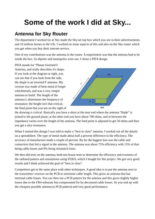
PIFA stands for “Planar Inverted F
Antenna, and really describes it's shape.
If you look at the diagram at right, you
can see that if you look from the side,
the shape is an inverted F antenna. My
version was made of bent metal (I forget
whichmetal), and was a very simple
antenna to build. The length of the
antenna L determines the frequency of
resonance; the height isn't that critical;
the feed point that you see on the right of
the drawing is critical. Basically you have a short at the near end where the antenna “blade” is
joined to the ground plane; at the other end you have about 700 ohms, and in between the
impedance varies over the length of the antenna. The feed point is adjusted to get 50 ohms and then
you get a nice resonance.
When I started this design I was told to make a “best in class” antenna. I worked out all the details
on a spreadsheet. The type of metal made about half a percent difference to the efficiency. The
accuracy of manufacture made a couple of percent. By far the biggest loss was the cable and
connectors that fed a signal to the antenna. The antenna was about 75% efficiency with 15% of that
being cable losses and 8% being mismatch loses.
We then did tests on the antenna; both test house tests to determine the efficiency and evenness of
the radiated pattern and simulations using FEKO, which I bought for this project. We got very good
results and I think achieved the goal of “best in class”.
Competitors get to the same place with other techniques. A good idea is to put the antenna next to
the transmitter/ receiver on the PCB to minimise cable length. This gives an antenna that has
minimal cable losses. You can then use a PCB pattern for the antenna and this gives slightly higher
losses due to the FR4 substrate but compensated for by decreased cable losses. So you end up with
the cheapest possible antenna (a PCB pattern) and very good performance.
2. Testing the Sky Router
The Sky router uses a Broadcom test set and with appropriate scripts you can test the receiver and
the transmitter of the router separately. I bought a Rohde and Schwarz wifi test set for testing the
router performance which turned out to be an excellent piece of apparatus.
An interesting thing on WiFi is that you have many, many modulation schemes; I could list them all
here and how they work, but that's a bit beyond the scope of this summary. But wifi is an expansive
standard with 11 wireless n modulation modes and all the a, b, and g modes also supported. The
sensitivity of the receiver changes between modes due to the effective bandwidth of the receiver.
Then you also have to test how the chipset switches between modulation modes; this can be very
relevant to the performance. And then you have MIMO (Multiple in, multiple out) and this also is
something that needs testing. It's quite an extensive bit of work, and automation using a scripting
language or Labview is important to get enough data.
A 5GHz antenna
This antenna was never made into a
product but I still think it's an idea
that could find it's place in the
world. The bottom layer is a PCB
with a ground plane and stripline
feed on the back. At the top is a
piece of metal tape forming the
patch antenna. In between is
transparent polycarbonate which is
glued to the PCB. It works really
well as polycarbonate is a low loss
dielectric (see Microwaves101.com
for a listing of materials). The case
of the router was made out of
polycarbonate and so with careful engineering it could have been an almost free 5GHz antenna.
Maybe one day it will find it's place in the world! Of course, polycarbonate melts easily and so you
can't solder anywhere near it.