
Recommended
Recommended
More Related Content
Similar to Documentation transmission remove & install
Similar to Documentation transmission remove & install (20)
Recently uploaded
Recently uploaded (20)
Documentation transmission remove & install
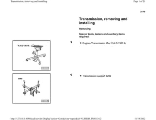
- 1. 34-18 Transmission, removing and installing Removing Special tools, testers and auxiliary items required: Engine-/Transmission lifter V.A.G 1383 A Transmission support 3282 Page 1 of 21Transmission, removing and installing 11/19/2002http://127.0.0.1:8080/audi/servlet/Display?action=Goto&type=repair&id=AUDI.B5.TM03.34.2
- 2. 34-19 3282/12 Adjustment plate VAG1306 Drip tray Page 2 of 21Transmission, removing and installing 11/19/2002http://127.0.0.1:8080/audi/servlet/Display?action=Goto&type=repair&id=AUDI.B5.TM03.34.2
- 3. 34-20 - Obtain radio code on vehicles with coded radio. - With ignition switched off disconnect battery Ground strap. - Loosen bolts (arrows) and remove engine cover panels (arrows -A- through -C-). - Detach air intake duct. To do this, pull off retainer catch -1-, loosen clamps -2- and unscrew bolts -3-. Page 3 of 21Transmission, removing and installing 11/19/2002http://127.0.0.1:8080/audi/servlet/Display?action=Goto&type=repair&id=AUDI.B5.TM03.34.2
- 4. 34-21 - Remove coolant system expansion reservoir and lay to one side. - Unplug connector for oxygen sensor on left (arrow -2-) and move wire for oxygen sensor clear. - Unplug connector for oxygen sensor on right -1- and move wire for oxygen sensor clear. Page 4 of 21Transmission, removing and installing 11/19/2002http://127.0.0.1:8080/audi/servlet/Display?action=Goto&type=repair&id=AUDI.B5.TM03.34.2
- 5. 34-22 - Unscrew two bolts securing heat shield -2- on exhaust pipe (right and left). - Unscrew nuts -3- on exhaust pipe (right and left). - Unscrew engine/transmission securing bolts accessible from above. - Remove noise insulation (arrows). Page 5 of 21Transmission, removing and installing 11/19/2002http://127.0.0.1:8080/audi/servlet/Display?action=Goto&type=repair&id=AUDI.B5.TM03.34.2
- 6. 34-23 - Unbolt bracket for noise insulation (arrow). Note: Take care not to damage protective coating on drive axles. - Unbolt heat shields from transmission above left and right drive axles (arrows). - Unbolt left and right drive axles -1- from transmission, lift clear and tie in position. Page 6 of 21Transmission, removing and installing 11/19/2002http://127.0.0.1:8080/audi/servlet/Display?action=Goto&type=repair&id=AUDI.B5.TM03.34.2
- 7. 34-24 - Loosen exhaust system clamps and push clamps towards rear. - Remove heat shield for driveshaft from cover for Torsen differential (arrows). - Unbolt driveshaft -1- from transmission and rest it on heat shield -2-. - Secure driveshaft to fuel pipe bracket -3- with wire (arrow). Page 7 of 21Transmission, removing and installing 11/19/2002http://127.0.0.1:8080/audi/servlet/Display?action=Goto&type=repair&id=AUDI.B5.TM03.34.2
- 8. 34-25 - Remove bolts (arrows) and remove transverse mount -A-. - Completely remove brackets -B- at right and left exhaust pipe. To do this, bolts -2- and -3- must be removed. - Unscrew and remove bolts -1- and -2- on right and left and remove support -A-. Page 8 of 21Transmission, removing and installing 11/19/2002http://127.0.0.1:8080/audi/servlet/Display?action=Goto&type=repair&id=AUDI.B5.TM03.34.2
- 9. 34-26 - Lower subframe at rear and place spacer (e.g. wedge of wood) in gap. -a- = max. 50 mm - Unscrew bolts -1- and -2- and remove right and left transmission supports from transmission and subframe together with bonded rubber mountings. Page 9 of 21Transmission, removing and installing 11/19/2002http://127.0.0.1:8080/audi/servlet/Display?action=Goto&type=repair&id=AUDI.B5.TM03.34.2
- 10. 34-27 Note: Avoid excessive bending of the flexible pipe connection (decoupling element) on the front exhaust pipe. The angle between the catalytic converter and the front exhaust pipe must not exceed 10 , otherwise the flexible connection will be damaged. - Loosen clamp -3-, lift heat shield -2- slightly and unscrew remaining nuts -5-. - Lift heat shield -2- and pull out front exhaust pipe together with catalytic converter -4-. - Note that oxygen sensor -1- and oxygen sensor wire have to be guided through opening in heat shield -2-. A - Axle stand B - V.A.G 1383A - Lift the transmission for access to the two lower bolts securing engine to transmission ( A34-0173 below). Page 10 of 21Transmission, removing and installing 11/19/2002http://127.0.0.1:8080/audi/servlet/Display?action=Goto&type=repair&id=AUDI.B5.TM03.34.2
- 11. 34-28 Note: The two hex socket head bolts M 10 x 60 must be replaced by new hex bolts M 10 x 55 (Part No. N 104 684 01) so that the two bolts (arrows) can be tightened with a torque wrench after installing the transmission. - Unscrew two bolts securing transmission to engine (arrows). - Lower transmission again slowly. Note: Do not disconnect cables at starter. - Remove engine speed sender -G28 from left-hand side of transmission (arrow) and place to one side. - Pull connector off sender for speedometer. - Pull off connector on reversing light switch. - Unbolt the starter and push it as far as it will go towards the front. Page 11 of 21Transmission, removing and installing 11/19/2002http://127.0.0.1:8080/audi/servlet/Display?action=Goto&type=repair&id=AUDI.B5.TM03.34.2
- 12. 34-29 - Unbolt connecting rod -2- for selector rod on right-hand side of transmission. - Remove hex socket head bolt from push rod -1-. - Unscrew nut -1- and pull selector rod lever -2- off transmission selector shaft. Page 12 of 21Transmission, removing and installing 11/19/2002http://127.0.0.1:8080/audi/servlet/Display?action=Goto&type=repair&id=AUDI.B5.TM03.34.2
- 13. 34-30 Notes: - Set up transmission support 3282 with adjustment plate 3282/12 for removal of manual transmission 01E (all-wheel drive) and place on transmission jack V.A.G 1383 A. A - Attachments The positions for the attachments are indicated by symbols (-A-). Arrow -B- points in the direction of travel. Adjustment plate 3282/12 can only be installed in one position. Page 13 of 21Transmission, removing and installing 11/19/2002http://127.0.0.1:8080/audi/servlet/Display?action=Goto&type=repair&id=AUDI.B5.TM03.34.2
- 14. 34-31 - Remove all but one of the engine/transmission securing bolts from below (one bolt is left in place to hold engine and transmission together). Note: If transmission support 3282 is not available, the transmission can be removed and installed using transmission jack V.A.G 1383 A. Note: When lowering transmission ensure hydraulic line/hose to slave cylinder is not damaged. - Run transmission jack V.A.G 1383 A with transmission support 3282 in under transmission and take up weight of transmission. - Secure transmission to transmission support 3282. - Remove last remaining engine/transmission securing bolt. - Press transmission off dowel sleeves and lower carefully with transmission jack V.A.G 1383 A just far enough for access to slave cylinder. Page 14 of 21Transmission, removing and installing 11/19/2002http://127.0.0.1:8080/audi/servlet/Display?action=Goto&type=repair&id=AUDI.B5.TM03.34.2
- 15. 34-32 Note: Do not depress clutch pedal after removing slave cylinder. Note: When lowering transmission ensure there is sufficient clearance to drive axles. - Remove bolt (arrow) and take out slave cylinder from the rear. Do not open line/hose system. - Lower transmission completely. Page 15 of 21Transmission, removing and installing 11/19/2002http://127.0.0.1:8080/audi/servlet/Display?action=Goto&type=repair&id=AUDI.B5.TM03.34.2
- 16. 34-33 Installing Installation is carried out in the reverse order, when doing this note the following: - Always replace all seals and gaskets. - Always replace all self-locking nuts. - Check whether dowel sleeves for aligning transmission with engine are in engine flange. Insert if necessary Page 34-36 . - Clean input shaft splines and (in the case of used clutch plates) hub splines. Remove corrosion and apply only a very thin coating of grease G 000 100 to splines. Do not grease guide sleeve. - Check clutch release bearing for wear and replace if necessary. - Coat area -a- of collar with lithium grease G 052 150 A2 before mounting slave cylinder into transmission housing. - Coat contact surface for clutch slave cylinder push rod with a thin layer of copper grease, e.g. Z381 351 TE. Page 16 of 21Transmission, removing and installing 11/19/2002http://127.0.0.1:8080/audi/servlet/Display?action=Goto&type=repair&id=AUDI.B5.TM03.34.2
- 17. 34-34 - On vehicle with V6 bi-turbo engine, fit intermediate plate on dowel sleeves on engine flange. - Two hex socket head bolts M 10 x 60 must be replaced by new hex bolts M 10 x 55 (Part No. N 104 684 01) so that two bolts (arrows) can be tightened with a torque wrench after installing transmission. - Before installing transmission, tie electrical wiring off to one side so that it cannot be trapped between engine and transmission. Repair Manual, 2.7 Liter V6 5V BiTurbo Engine Mechanical, Engine Code(s): APB, Repair Group 26 - Lift transmission until clutch slave cylinder with bracket for line/hose can be installed (arrow). - Align exhaust system free of stress. - Before installing, use a tap to clean threads in drive flange for driveshaft on transmission to remove traces of locking compound. - Replace gaskets on drive axles and on front of driveshaft Page 39- 65 . Page 17 of 21Transmission, removing and installing 11/19/2002http://127.0.0.1:8080/audi/servlet/Display?action=Goto&type=repair&id=AUDI.B5.TM03.34.2
- 18. 34-35 - Bolt on driveshaft Page 39-71 . - Check adjustment of selector rod and push rod; readjust if necessary Page 34-12 . - Check oil level in transmission Page 34-39 . - After connecting battery, enter anti-theft code for radio Radio operating instructions - Close windows fully using electric window switches. - Operate all electric window switches again for at least one second in "close" direction to activate automatic one-touch function. - Set clock to correct time. Page 18 of 21Transmission, removing and installing 11/19/2002http://127.0.0.1:8080/audi/servlet/Display?action=Goto&type=repair&id=AUDI.B5.TM03.34.2
- 19. 34-36 Vehicles with 6-cyl. bi-turbo engine Dowel sleeves -A- for aligning. 1) The two hex socket head bolts M 10 x 60 must be replaced by new hex bolts M 10 x 55 (Part No. N 104 684 01) so that the two bolts -4- can be tightened with a torque wrench after installing the transmission. No. Bolt Qty. Nm 1 M 12 x 90 2 65 2 M 12 x 100 1 65 3 M 10 x 60 1 45 4 M 10 x 60 1) 2 45 5 M 10 x 150 1 65 6 M 12 x 130 1 65 7 M 12 x 80 2 65 Page 19 of 21Transmission, removing and installing 11/19/2002http://127.0.0.1:8080/audi/servlet/Display?action=Goto&type=repair&id=AUDI.B5.TM03.34.2
- 20. 34-37 Component Nm Clutch slave cylinder to transmission 1) 20 Transmission support to transmission 40 Engine speed sender -G28- 10 Drive axle to drive flange M8 M10 40 80 Heat shields above drive axles to transmission 25 Push rod to transmission 40 Selector rod to transmission 23 Connecting rod for selector rod to transmission 23 Catalytic converter to mounting lugs 25 Front exhaust pipe to turbocharger 30 Heat shield to turbocharger/exhaust pipe 10 Clamp for exhaust pipe 40 Bracket for noise insulation to subframe 10 Driveshaft to transmission 1) 55 Heat shield for driveshaft to Torsen differential cover 25 1) Always replace bolts Page 20 of 21Transmission, removing and installing 11/19/2002http://127.0.0.1:8080/audi/servlet/Display?action=Goto&type=repair&id=AUDI.B5.TM03.34.2
- 21. 34-38 Subframe to body 1) Always replace bolts washers Support -A- to body -arrow 1- 75 Subframe to body 1) (arrow -2-) 115 + 90 Transmission mounting to subframe (arrow -3-) 25 For 6-cylinder bi-turbo engine only 1) Install bolts -1- from the bottom. Always replace nuts and bolts. Cross-piece -A- to subframe 1) 40 + 90 Page 21 of 21Transmission, removing and installing 11/19/2002http://127.0.0.1:8080/audi/servlet/Display?action=Goto&type=repair&id=AUDI.B5.TM03.34.2