1. 1
Power Management - a Hardware/Software Approach
Ayan Kumar Halder
Open-Silicon Research Private Limited
Pune, India
Ayan.Halder@open-silicon.com
Abstract
This paper analyses the power consumption of an
embedded system device. It proposes a hardware/software
coupled power management solution which aims to maximize
power saving during system-idle and system-operation phases.
I. INTRODUCTION
The paper begins with a brief description of the two
forms of power consumption for an embedded system device.
It then describes our power management solution, the various
hardware/software components involved and analyzes the
power savings obtained in various scenarios.
II. TWO FORMS OF POWER CONSUMPTION
A typical embedded device would experience two
forms of power consumption. They are as follows:-
1. Dynamic Power Consumption: This is the power
consumption required for the charging/discharging of
capacitances or toggling of flip-flops at a rate
determined by its clock frequency. It is represented
by:-
P = CV2
F where:-
P is power consumption, V is supply voltage and F
stands for clock frequency.
Thus for any IP like CPU, DDR, etc its dynamic
power consumption is directly proportional to its
clock frequency (assuming that the supply voltage is
constant). If we increase the clock frequency, the
dynamic power consumption increases and vice
versa. If the clock frequency drops to zero, the
dynamic power consumption too reduces to zero.
However, the IP still continues to consume a small
amount of power which is known as Leakage Power
Consumption.
2. Leakage Power Consumption: This is caused due to
power leakage of transistors, flip-flops, etc. This is
independent of clock frequency. In today’s systems
(using 40nm technology), this forms a considerable
part of the total system power consumption. The only
way to eliminate this form of power consumption is
to turn off its power supply.
Our system under consideration is a home gateway
solution. It comprises of ARM CPU cores (A9x3),
caches, various memory, Input/output controllers,
Power Management Unit (PMU - custom IP) and
various off-chip components including DDR and
Power Management Integrated Circuit (PMIC).
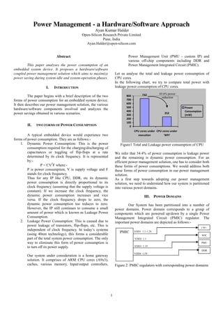
Let us analyse the total and leakage power consumption of
CPU cores.
In the following chart, we try to compare total power with
leakage power consumption of CPU cores.
732
252
0
100
200
300
400
500
600
700
800
CPU cores under
execution
CPU cores under
'WFI'
Power
Consumption
(mW)
Figure1 Total and Leakage power consumption of CPU
We infer that 34.4% of power consumption is leakage power
and the remaining is dynamic power consumption. For an
efficient power management solution, one has to consider both
these forms of power consumptions. We would address both
these forms of power consumption in our power management
solution.
As a first step towards adopting our power management
solution, we need to understand how our system is partitioned
into various power domains.
III. POWER DOMAINS
Our System has been partitioned into a number of
power domains. Power domain corresponds to a group of
components which are powered up/down by a single Power
Management Integrated Circuit (PMIC) regulator. The
important power domains are depicted as follows:-
Figure 2: PMIC regulators with corresponding power domains
PMIC
CPU
SOC
PMU
DDR
VDD1 1.1-1.2V
VDD2 1.1
VDD3 1.1V
VDD4 1.5V
65.6% power
reduction
2. 2
1. CPU Power Domain: This consist of ARM A9x3
cores, L2 cache, Snoop Control Unit(SCU), Generic
Interrupt Controller(GIC) and Accelerator Coherency
port(ACP).
2. System On Chip (SOC) Power domain:- This consist
of all memory and I/O controllers (eg Nand Flash
controller, PCI controller, etc).
3. DDR Power domain :- This consist of DRAM chips
4. PMU Power domain:- This consist of Power
Management Unit. This is the wakeup domain for all
the other power domains and hence is never powered
down. It controls the power to all the other domains.
This leads us to the two important hardware components
involved in power management. They are described as
follows.
IV. HARDWARE COMPONENTS OF POWER MANAGEMENT
The two hardware components that play role in our power
management solution are:-
1. PMIC
2. PMU
Power Management Integrated Circuit (PMIC):
PMIC is a set of power regulators which provides
power to our power domains. This is interfaced to our SOC
via I2C. Thus it helps to independently power up/down and
regulate the voltage/current of the various domains.
Refer Figure 2 for PMIC with its set of regulators (Vdd1,
Vdd2, Vdd3, Vdd4) which provides power to the respective
domains.
Power Management Unit (PMU):
This IP plays a central role in the power management
of our system. The various functions performed are as
follows:-
1. It receives clocks from various PLLs. It generates and
scales clock frequencies for various IPs like CPU,
DDR Controller, PCIE controller etc. It controls
clock gating for these IPs.
2. Supports DVFS (Dynamic Voltage Frequency
Scaling) for CPU.
3. Interfaces the PMIC regulators to control their output
voltage/current or shut-down/power-up them.
4. It has a power control sequence controller and
controls reset of various power domains.
5. It has a APB interface for its register configurations.
6. This is the wakeup domain for all other power
domains and thus is always powered on. It receives
an external interrupt to wake up (ie resume power,
exit idle mode) the other domains.
Shown next is the architectural diagram of a PMU
PMU
Figure 3: Block Diagram of PMU and associated components
Having understood the two forms of power consumption and
the Hardware Components involved in power regulation, let us
try to analyze our power management (PM) solution which
takes into consideration both the forms of power consumption
and uses PMU, PMIC, Power Management Software
Frameworks and various device drivers as its tools for power
management.
Our system has a thermal management mechanism also in
place which reads the SOC temperature from a sensor (who
further obtains it from an on-chip temperature diode). Based
on the temperature, our software decides to reconfigure the
Pulse Width Modulation (PWM) Controller to
increase/decrease the cooling fan’s speed.
Let us begin the understanding of our PM solution by
identifying the various scenarios of power savings.
V. MODES OF POWER MANAGEMENT
Embedded system devices can have two scenarios for saving
power 1. The device is idle and 2. The device is functioning.
In accordance to these scenarios, we have defined the
following two modes of power management.
1. System Power Management. – This saves power
when the system is idle by suspending the system. It
tries to reduce leakage + dynamic (= System) power
consumption.
2. Runtime Power Management – This saves power
when the system is performing its usual functions. It
tries to reduce dynamic power consumption only.
Clock generation for
various IPs
Power Control Sequence
Reset Generation for
various IPs
PMIC Regulator
Controller
PMU Register Controller
Clock for
various IPs
Powers Down/
Wakes up various
power domains
External Interrupt
for wake-up
Reset for various
IPs
PMIC
I2C
APB
Interface
PWM Controller
SOC
Temp
Sensor
Controls Fan’s
speed
Temp
Diode
I2C
Various
PLLs
Xtal
3. 3
System Power Management:
Under System Power Management, the power is
managed at the granularity of power domains ie some of the
power domains (Refer Figure2) are independently powered
down/kept at low power state. Based on the amount of power
saved and wake-up latency, we have defined the following
four sleep states (ordered from lightest to deepest sleep). PMU
is the wake-up domain for all the other power domains and
thus is always powered up. The system wakes-up when PMU
receives an external interrupt.
1. Halt -. Here the CPU cores are put in wait for
interrupt (wfi) mode. Thus most of the CPU
clocks are turned off and its power consumption
drops nearly to its leakage power. Whenever the
CPU receives any interrupt, it resumes the next
instruction from 'wfi'. The other power domains
remain fully powered.
2. Doze – In this mode the CPU power domain is
turned off. Thus its total power consumption
drops to zero. The other domains remain
powered. The CPU saves its context to DDR
before it gets turned off. When the PMU receives
the external interrupt, it powers up the CPU. The
CPU restores its context and resumes its
execution. Thus the power saved and wake-up
latency is more than that of ‘Halt’.
3. Sleep – In this mode, besides the CPU, the SOC
power domain too, gets turned off and DDR
enters into a self-refresh state. Thus the CPU and
the various memory/IO controllers of SOC save
their context to DDR. On PMU receiving the
wake-up interrupt, it powers up the SOC, enables
auto-refresh of DDR and powers up the CPU.
The CPU restores its context and that of the
various controllers in SOC and resumes.
4. Hibernate – This is the deepest sleep state. In this
mode, in addition to CPU and SOC, the DDR,
too is powered down. Thus the context gets
saved to an external flash. PMU (on receiving
wake-up interrupt) wakes up the DDR, SOC and
CPU. The CPU restores the system context and
resumes its execution. Thus in this state we
achieve maximum power savings at the cost of
maximum wake-up latency.
System Power Management is supported by Operating System
Power Management (OSPM) Framework. It is a software
framework which identifies the procedure for entering/exiting
an Idle state. The procedure is briefly described as follows.
The flow for entering a System Idle state is as follows:-
The flow for resuming the system is as follows:-
The system power consumption/savings of the various modes
are depicted in the diagram below:
5160
3720 3648
720
264
0
1000
2000
3000
4000
5000
6000
Normal Halt Doze Sleep Hibernate
Power Consumption (mW)
Figure 4: Power Consumption in various modes
The following table describes the power savings in each sleep
state for each domain (with its power state)
Halt Doze Sleep Hibernate
System Power
Savings
27.9% 29.3% 86.04% 94.8%
CPU Power
Savings
65.6%
(wfi)
100%
(off)
100%
(off)
100%
(off)
SOC Power
Savings
0%
(off)
0%
(on)
100%
(off)
100%
(off)
DDR Power
Savings
0%
(on)
0%
(on)
22%
(self-refresh)
100%
(off)
PMU Power
Savings
0%
(on)
0%
(on)
0%
(on)
0%
(on)
Table 1:- Power Savings in various sleep states
Software receives system suspend notification
All the active processes are frozen
Various device drivers suspend their devices
Interrupts are disabled, System context is saved,
PMU receives wake-up notification
PMU powers up the needed domains
CPU restores context, resume execution. Interrupts
are enabled
Various device drivers resume their devices (and
restore their context if needed)
Unfreeze all processes
PMU powers down the needed domains
4. 4
Run-time Power Management
This plays its role when the device is functioning.
Thus it looks for scope of reducing power when the system
load is less or when some of the IPs stay idle for some
duration. Based on the IPs involved and procedure of saving
runtime power, we have defined the following three software
driven power management mechanisms:
1. CPU Idle management
2. CPU frequency management
3. Devices runtime power management
CPU Idle Management
This involves putting the CPU cores in 'wait for
interrupt (WFI)' state when the CPU is not in use. WFI is the
highest power saving state for the CPU. As soon as CPU
receives an interrupt, it comes out of idle state and moves to
working state. Thus it keeps CPU on a low power mode
during the time it is not used.
If one refers to Table1, one can see that by moving the CPU to
idle state (in case of ‘Halt’), can save 27.9% of the total
system power (when functioning) and 65.6% of CPU power.
While Halt mode is a system based power management
decision, CPUIdle mode is an independent policy of each
CPU, who voluntarily enters into ‘wfi’ state under no load.
Procedure –
When our system was performing the role of router and it was
operating at a bandwidth of 400Mbps for 30 mins, then the
total idle time obtained was 13.5 seconds.
CPU Frequency Management
It involves down-scaling the CPU frequency when
the load is less and up-scaling the CPU frequency when the
load increases. The CPU supply voltage too decreases and
increases correspondingly. This phenomenon is known as
Dynamic Voltage Frequency Scaling (DVFS).
Thus we have set the upper and lower thresholds for
CPU load. If it crosses the upper threshold, the CPU frequency
driver increases the CPU frequency with the help of PMU and
increases CPU power regulator (Vdd1, refer figure2) output
voltage with the help of PMIC’s driver. The opposite happens
when the CPU load reduces below its lower threshold.
Thus CPU frequency scaling procedure can be
diagrammatically described as follows:-
The following table describes the CPU frequency with respect
to System Power Consumption
Freq 100 200 300 400 500
Power 4500 4620 4680 4752 4812
Freq 600 700 800 900 1000
Power 4872 4908 4944 4968 4992
Frequency is in MHz and Power is expressed in mW
Table 2: Current Consumption w.r.t CPU frequency
For our system, the CPU frequency ranges from 100MHz to
1000MHz (in steps of 100MHz) and its supply voltage
correspondingly scales from 1.1V to 1.2V.
CPU Supply Voltage (V)
Min Max
CPU Frequency (MHz)
1.1 1.125 100
1.125 1.1375 200
1.1375 1.150 300
1.150 1.1625 400
1.1625 1.175 500
1.175 1.1875 600
1.1875 1.2 700
1.2 1.2 800
1.2 1.2 900
1.2 1.2 1000
Table 3: Frequency scaling with Voltage
We describe the following two scenarios to demonstrate
power savings due to CPU frequency scaling:-
Scenario1 - Under light system load
Without CPU frequency scaling: It means the CPU is running
at constant frequency of 1000MHz
Supply voltage = 12V
Current = 416mA
Scheduler calls CPUIdle routine when it has no process to
schedule
CPUIdle routine predicts the idle time
Determine the CPU idle state to enter (There can be many
CPUIdle states). If the predicted idle time is greater than a
particular idle state’s resident time (time taken to enter idle
state), enter the idle state. In our case the only idle state is ‘WFI’
Exit Idle state and execute processes
Check the CPU load
Is
Load >
Threshold
Set PMU to configure target CPU frequency
Set I2C commands to set CPU Voltage
Increase CPU frequency
Decrease CPU frequency
Yes
No
5. 5
Power drawn by the system = 12V x 416 mA
Energy consumed in an hour = 4992mWh
With CPU frequency scaling: It means that CPU frequency
varies with system load. Our system is at its lowest frequency
due to light load.
Supply voltage = 12V
Current = 375mA
Power drawn by the system = 12V x 375 mA
Energy consumed in an hour = 4500mWh
Total savings of system energy due to CPU frequency scaling
in an hour is ~10%.
Scenario 2- Our system was functioning as a router for around
12.36hrs. We obtained the following statistics:-
CPU
Frequency(MHz)
Time spent in
seconds (Total =
44521.08)
Energy spent
(mWh) Total =
57369.89
100 2452.57 3065.71
200 23139.26 29695.38
300 18890.38 24557.49
400 38.87 51.31
If we did not have CPU frequency scaling, then our power
consumption (for the same duration) would be 61375.89mWh.
Thus the net power savings is 7.11%.
IP runtime power management:
It involves suspending the IPs (Intellectual Property
eg Memory Controllers, IO Controllers, etc) at runtime when
they are not in use. Runtime suspending involves lowering the
clock frequency, turning off some of the unused logic of the
IP, etc while still keeping it sufficiently powered to receive
interrupts. This is a IP driver driven power management
mechanism.
The procedure is as follows:-
CONCLUSION
Thus we have seen how our PMU collaborates with other
hardware components like PMIC, other IPs, etc and software
frameworks like Operating System Power Management
Framework, CPU-Idle , CPU-Frequency and various device
drivers to ensure maximum power savings during System-Idle
and System-Operational phases.
ACKNOWLEDGEMENT
I would like to thank Mr Shreepad Hardas, Mr Nitin Lahane
and Mr Pradeep Sukumaran for guiding me on this paper.
Further I would like to express my regards to Mr Amit Gupta
and Mr Swapnil Jakhade for their valuable inputs.
REFERENCES
http://www.ti.com/lit/wp/sprt495/sprt495.pdf
http://www.xilinx.com/publications/archives/solution_guides/power_manage
ment.pdf
http://elinux.org/Static_Power_Management_Specification
http://infocenter.arm.com
http://ip.cadence.com/uploads/pdf/hillman_slides.pdf
Device receives interrupt
Driver ‘runtime-resumes’ IP ie scales its clock to
highest frequency with the use of PMU
IP finishes handling interrupt
Driver ‘runtime suspends’ IP ie scale its clock to
lowest frequency with the use of PMU