+971581248768>> SAFE AND ORIGINAL ABORTION PILLS FOR SALE IN DUBAI AND ABUDHA...
4-Turbines.pptx
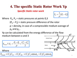
1. 4. The specific Static Rotor Work Yp
Specific Static rotor work
Where P0, P3 = static pressures at points 0,3
(P0 – P3) = static pressure difference of the rotor
ρ = density, in case of a compressible medium average of
ρ0 and ρ3 .
Yp can be calculated from the energy difference of the flow
medium between o and 3
Where
0
3
1
P
P
YP
2
2
0
2
3
0
3 C
C
P
P
Z
Y u
blade
0
0
1
3
3
2
0
1
3
2 cos
cos
C
U
C
U
C
U
C
U
Y U
U
blade
1
3. • Applying the cos-theorem of a triangle
• It follows
C
b a
α
U
C W
α
2
2
2
cos
2 a
c
b
bc
2
2
2
cos
2 W
U
C
CU
2
2
2
2
2
2
2
2
2
2
2
2
3
0
0
3
0
3
0
0
0
3
3
3
2
1
2
1
W
W
U
U
C
C
W
U
C
W
U
C
Yblade
u
u
blade
P Z
W
W
U
U
Z
C
C
Y
Y
2
2
2
2
2
0
2
3
3
0
0
3
2
1
2
3
0
0
1
3
3
2
0
1
3
2 cos
cos
C
U
C
U
C
U
C
U
Y U
U
blade
4. Bernoulli Equation of the Relative Flow
• Neglecting the hydraulic loss, i.e. Zu = 0,
• It follows
• The above formula applies to any points along the flow line
passing the vane channel
2
2
2
2
2
2
2
3
2
2
0
3 1
0
U
W
U
W
P
P
YP
2
2
2
2
2
1
2
0
0
2
2
2
3
3 U
W
P
U
W
P
const
U
W
P
2
2
2
2
Bernoulli Equation of the
Relative Flow
4
5. Impulse and Reaction Type of
Turbomachines
• Considering YP, the turbomachine can be grouped into:
A. “Impulse” type of Turbomachines
B. Reaction type of Turbomachines
5
Yp=0, P3=P0
Po<P3
6. Equal Pressure or Impulse Type of
Turbomachines
• Example A. Single-Stage Steam Turbine 0
0
0
3
P
Y
and
P
P
6
The entirely available pressure difference (P3-P0) is
converted into velocity in the stationary guide vanes
Turbomachines without pressure difference in front of and beyond the rotor.
7. • The velocity existing in the clearance between the stationary
guide vanes and the rotor blades is the highest , i.e. C3 = C3max
attainable
• The absolute velocity is reduced from C3 to C0 ,While the flow
passes through the rotor.
• The specific static rotor work Yp is (for axial flow U1=U2 = U)
u
P Z
W
W
Y
2
3
2
0
2
1
7
Impulse Type
2
2
2
2
2
2
2
3
2
2
0
3 1
0
U
W
U
W
P
P
YP
8. • Neglecting the hydraulic lose Zu of the
rotor, it follows because Yp = 0.
• Considering the loss:
• Where the velocity coefficient φ takes in to account the drop
in kinetic energy due to Zu; Ф<1.
• The condition Wo ≈W3 demands rotor blades of the ‘hook-
form’ type, i.e. β2 >900.
3
0 W
W
3
0 W
W
Blades of a constant-pressure steam
or Gas turbine. ‘a’ is the channel
width at all points approximately
equal
8
Impulse Type
u
P Z
W
W
Y
2
3
2
0
2
1
9. • If blade has uniform thickness, the flow while passing the
channel is first decelerated then accelerated.
• Such change in the flow velocity is undesirable as it leads to
unnecessary losses.
• In order to obtain W≈ const. along the vane channel the
blade be designed with strong profiling; however, such blades
are costly
9
Impulse Type
10. • The specific work Yblade of an impulse steam turbine stage as for a
given velocity U2 proportional to the velocity C3
• Steam turbines are designed with approximately the same angle
α3=15 to 20 degrees.
• As C3 of impulse steam turbines has highest possible value C3max-att.
The spec. work Yblade of these turbines has highest value
• The peripheral velocity U2 will be lowest for a given Yblade if
the turbine is designed as impulse turbine
• Impulse turbines are slow running turbines
.
max
3
3
3
3
2
3
2 cos att
U
blade C
C
C
U
C
U
Y
For α0=900
2
.
.
max
. U
given
a
for
Y
Y att
blade
t
impulse
blade
10
11. Over-Pressure or Reaction Type of
Turbomachine
• Example B: Single-Stage Reaction Steam Turbine
11
•Part of the pressure drop occurs across the guide
vanes and part occurs across the rotor,
Turbomachines with pressure difference in front and
beyond the rotor, i.e. (P3-P0) ≠ 0 Yp> 0
12. • Thus C3<C3max-attainable and, hence, the spec. work Yblade =U2C3U
of the reaction turbine is smaller than that of the impulse
turbine if the same velocity U2 is assumed
• The velocity U of reaction turbines has to be higher than that
of impulse turbines if the same Yblade is to be obtained.
• Reaction turbines may be classified as fast running
turbomachines.
12
Comparison of Impulse and Reaction
Turbines
13. Comparison of Impulse and Reaction
Turbines
• β1 should be small but not too small as leads to strong
whirls in the discharge flow.
• The angle β2 of reaction turbines is β2≤900 and, thus,
differs from that of impulse turbines.
• The blade of reaction turbine does not have the hook
form.
• As the relative velocity increases from W3 to W0, the
channel width decreases and no profile is necessary in
order to obtain equal channel width.
• Reaction turbine has more stages because of the lower
Yblade of its single stage. 13
14. Summary
– Impulse turbines: High-head, low
flow rate devices.
– Moving blade row changes only the
direction of the steam.
– Reaction turbines: Low-head, high-
flow rate devices.
• Moving blade row changes both
the speed and direction of the
steam
14
Comparison of Impulse and Reaction
Turbines
16. Blade Speed Ratio
• The blade speed ratio as defined below is widely used in the
calculation of turbines especially of steam turbines.
• is the velocity which could be obtained if the spec.
work Y is converted without losses completely into velocity.
Y
U
C
U
Ratio
Speed
Blade
Y 2
Y
CY 2
R
C
CY
1
2
Where Ф is velocity coefficient of guide vanes
(referring to velocity losses)
R
C
U h
Y
1
1
cos
2 2
After some derivation
16
17. • Assuming the following data: ηh = 0.85;φ=0.98; α2= 300.
• The blade speed ratio has the value
• The following values of the blade speed ratio re obtained with
actual machines:
1
cos
2 2
h
5
.
0
2
1
0
2
1
5
.
0
0
R
for
C
U
R
for
C
U
R
Y
R
Y
47
.
0
44
.
0
1
47
.
0
35
.
0
1
'
'
47
.
0
35
.
0
0
0
arg
.
0
to
C
U
Turbines
Pelton
R
to
R
k
C
U
turbines
steam
reaction
k
to
C
U
turbines
steam
impuse
R
Y
R
Y
power
e
l
design
quality
high
power
small
Design
Cheap
R
Y
17
18. Influence of the Vane Angle β2,
on the size of the rotor of Turbomachinery
• Three different axial-flow vanes, namely form A, B, C for
which U2, C2m and β1 are the same but the angle β2 differ
18
19. • A similar sketch for three different radial-flow vanes with
β2<900 (form a), β2=900 (form b) and β2>900 (form c) is given
below.
• Vanes form b, c as ‘forward-curved’ vanes
19
Vane form a as ‘backward-curved’ vanes
Influence of the Vane Angle β2,
on the size of the rotor of Turbomachinery
20. The following relation exists between β2 and U2
Case:α0=900
Case:α0≠900
20
blade
m
m
m
blade
m
U
u
u
blade
U
blade
Y
C
C
U
follows
it
and
C
U
U
Y
then
C
U
W
U
C
where
C
U
Y
and
C
U
Y
2
2
2
2
2
2
2
2
2
2
2
2
2
2
2
2
2
2
3
2
tan
2
tan
2
cot
,
cot
,
OU
blade
m
m
C
U
Y
C
C
U 1
2
2
2
2
2
2
tan
2
tan
2
Influence of the Vane Angle β2,
on the size of the rotor of Turbomachinery
21. • The necessary peripheral velocity U2 for a given Yblade∞ can be
determined by these equation if the vane angle β2 is assumed.
• A large β2 , decreases U2 and the size of the rotor decreases,
too, if the speed n is not altered:
21
OU
blade
m
m
C
U
Y
C
C
U 1
2
2
2
2
2
2
tan
2
tan
2
Influence of the Vane Angle β2,
on the size of the rotor of Turbomachinery
22. • The rotor shape is a function of n, V and Y.
• Shape number (Nshape) is a dimensionless number
and is used to define the shape of the rotor by relating n, V
and Y.
• It follows
22
0
0
2
2
3
1
2
2
3
1
1
;
1
,
1
1
s
m
s
m
s
m
s
assume
s
m
Y
s
m
V
s
n
Nshape
4
3
4
/
3
2
/
1
1
1
Y
V
n
Y
V
n
Nshape
4
3
2
3
2
,
2
1
0
2
1
0
2
1
:
0
2
3
:
or
thus
or
S
m Thus,
shape
sh N
n 1000
Shape Number
23. Shape Number
1. Effect of Increase in speed n on the shape of
the rotor (with unchanged β2,V and Y)
The unchanged Y demands the same velocity triangle at 2.
The unchanged velocity triangle can be obtained for
increased speed n but same velocity U as demanded by the
unchanged velocity triangle only at a smaller outer diam.
23
U
blade
blade C
U
Y
Y
Y 2
2
4
3
4
/
3
2
/
1
1
1
Y
V
n
Y
V
n
Nshape
24. 1. Effect of Increase in speed n on the
shape of the rotor
(with unchanged β2,V and Y)
24
4
3
4
/
3
2
/
1
1
1
Y
V
n
Y
V
n
Nshape
25. 2. Effect of Increase in V on the shape of the
slow running rotor
(with unchanged β2,n ,D2,and Y)
The larger volume V can be obtained only by increasing the
channel width (b) and the eye dia. Ds
The meridian component of the velocity must remain
unchanged because of the unchanged Y with same n and D2
Demanding unchanged velocity triangle at 2.
25
4
3
4
/
3
2
/
1
1
1
Y
V
n
Y
V
n
Nshape
m
om C
b
r
C
b
r
V 3
3
3
1
1 2
2
26. • A relation which is based on the head H instead on the spec.
work Y is called Specific Speed.
• Where the values has a unit of n(rpm), V(m3/s) and H(m).
• nq is not dimensionless for metric system nq has the following
unit
• For water turbines a specific speed derived from n, H and N is
often used.
26
4
3
H
V
n
nq
min
.
333
min
1
60
81
.
9
4
3
4
3
2
4
3
s
m
N
N
s
s
m
n shape
shape
q
4
5
H
N
n
ns
Specific Speed
27. Comparison of pump profile
27
Pump selection is done based on the specific speed.
29. • Ns varies from 500 (centrifugal pump) to
10, 000 (propeller pump).
The Ns of a pump is closely related to the maximum
operating efficiency of the pump.
Operating efficiency : ratio of the power imparted by
the impeller to the water compared to the power
supplied to the pump by the motor.
The performance curve indicates that careful attention
must be given to the discharge requirements of the
pump , which determine the specific speed, so the
most suitable pump may be selected.
32. Values of Shape Number and
Specific Speed
Values of Nshape, nq and ns:
1000Nshape nq (water turbine)ns
Slow- running rotor 33 to 120 11 to 38 40 to 140
Medium-running rotor 120 to 250 38 to 82 140 to 300
Fast –running rotor 250 to 500 82 to 164 300 to 600
axial-flow rotor 330 to 1500 110 to 500 400 to 1800
32
33. Example
• The quantity of water available for a hydro
electric power is Q=260 m3/sec under a head of
H=1.73 m. Assuming the speed of the turbine to
be n=50 rpm & there efficiency to be 82.5%.
Find the number of turbines required.
33
Assume for the example , ns = 890 (metric units).
34. Solution
34
4
5
73
.
1
50
890
N
We have:
N = 1247.255MHP = 917356.05W
Ntotal=ηρQY=ηρQgH = .825*1000*260*9.81*1.73
Ntotal=3640343.85 W
Number of turbines = Ntotal/N
= 3640343.85 / 917356.05 =3.9 =4(Answer)
4
5
H
N
n
ns
35. Example
• At a location, the head available was 50 m. The
power estimated is 40,000 kW. The speed
chosen is 600 rpm. Determine the specific
speed and indicate the suitable type of turbine.
35
36. Example of Application of Nshape, in the
design of Turbomachinery
• Given, design radial blower for V=1.5m3/s,
Y=5000m2/s2 with good efficiency. Determine
the shape of the rotor.
• Solution
The speed n should be selected so that n=n
(synchronous speed motor should be used to
drive)
36
4
3
4
/
3
2
/
1
1
1
Y
V
n
Y
V
n
Nshape
rpm
to
s
to
s
to
V
Y
N
n shape 3305
966
1
5
.
58
1
16
22
.
1
594
10
)
120
33
( 3
4
/
3
37. Solution
• To get a good efficiency, n=2950 rpm is
selected from table.
• Therefore, the designed impeller has a shape
number:
• Which is in the range of a slow-running rotor.
37
34
.
333
10
.
101
594
22
.
1
2
.
49
1 3
4
3
4
/
3
2
/
1
1
shape
shape N
or
Y
V
n
Y
V
n
N