SlideShare a Scribd company logo
1 of 80
Download to read offline
RANGE OF PRODUCTS AND SERVICES
IDEAS FULL
OF ENERGY!
As our energy resources grow ever scarcer, it is increasingly essential that we make
more efficient use of our existing sources of energy – or find entirely new sources for
thermal utilisation. That is why our expertise is in greater demand than ever before.
In the following pages, you will find out how we transform ideas into energy.
2
Since December 2014 Standardkessel Baumgarte Group belongs to JFE Engineering
Corporation. JFE Engineering Corporation, a subsidiary of JFE Holding Inc., is a market
leader for „Grate Firing Systems“ and „Gasifying and Direct Melting Furnace Systems“.
With more than 350 furnaces installed, JFE Engineering has its main experience in the
Japanese market. With regard to biomass power plants, JFE Engineering is specialized
on the construction of large sized power plants employing circulating fluidized bed boilers.
CONTENT
	
1	
2	
3	
4
5	
6	
7	
8	
	
COMPANY PROFILE				04
ENERGY FROM WASTE				06
ENERGY FROM BIOMASS				20
ENERGY FROM WASTE HEAT				 28
ENERGY FROM PRIMARY FUELS			 40
PROCESS TECHNOLOGY				46
PLANTSERVICES FROM A TO Z			 62
INNOVATIVE TECHNOLOGIES			66
CUSTOMER REFERENCES				74
3
EXPERIENCE IS
OUR BEST INVESTMENT.
INTELLIGENT SOLUTIONS FOR EVERY FACET OF YOUR ENERGY SUPPLY.
There are many ways in which different sources of energy can be transformed into
heat, steam and electricity. At Standardkessel Baumgarte we not only know these
ways – we also find new ones. Thanks to our more than 160 years of experience, we
have incomparable process expertise, regardless of whether it concerns, the supply
of high-quality components, the implementation of complete complex systems, the
provision of services as an EPCM contractor or the delivery of top-notch plant
services. Even new energy concepts such as contracting are becoming increasingly
attractive options for many customers.
It is therefore no surprise that energy supply companies, municipal governments,
public utilities and industrial firms all rely on our know-how in these matters.
That is because they know that experience is our best investment.
Company Profile
4
5
PUTTING RESIDUES
TO WORK
ENERGY FROM WASTE
Fuel Household and household-type industrial waste, production waste, used tyres, blast furnace gas, coke gas,
liquid and gaseous industrial waste.
Performance range Solid residues up to 140 t/h – 500°C – 100 bar / Liquid, gaseous residues up to 600 t/h – 570°C – 170 bar
Boiler technology Steam generator operating in natural circulation with two or three vertically arranged radiation passes and a down­
stream convective pass. The first, second or third boiler pass are in empty pass construction and form the combustion
and ­radiation area. The vertical or horizontal convective boiler pass is equipped with the superheater, ­evaporator
and economiser convective heating surfaces. All convective heating surfaces can be cleaned with a rapper while in
operation. Depending on the profile for requirement, boiler constructions with the installation of 3 or 4 passes
can be applied. The temperature of the superheated steam is regulated by a multistage injection cooler between
the heating surfaces of the superheater.
Combustion system Air or water-cooled pusher-type grate with ram feeder
Combustion that is highly resilient both thermally and mechanically with intelligent combustion control. The fuel
is metered by a plunger feeder. Every grate zone can be controlled individually, including a multistage primary air
distributor. The secondary air is injected via nozzle trays arranged in the first and rear wall of the furnace area.
Fluidised bed firing
The fuel is fed through openings of the evaporator side walls of the combustion chamber into the fluidised bed.
The combustion air and the recirculated flue gas is injected into the fluidised bed and into the combustion chamber
at different levels as secondary and tertiary air-injection.
Industrial combustion systems for liquid and gaseous fuels
Combustion technology for low-NOx
industrial and power station combustion systems. The selection and configuration
of the burners is performed in accordance with the burner performance within the enclosing walls of the com­
bustion chamber.
Fuel gas treatment Reliable compliance with legal emission limits is ensured by a downstream flue gas cleaning system. Quasi-dry,
conditioned dry and dry process versions are deployed. Calcium hydroxide Ca(OH)2
, calcium oxide CaO or NaHCO3
are fed into the flue gas as additives for the absorption of the acidic gas components. As an alternative, wet
pro­cesses may also be used. The separation of heavy metals and organic substances such as dioxins and furans is
performed using adsorption with activated lignite coke or activated carbon. Fabric filters, electrostatic precipitators
or cyclones are used to ensure the required particle separation. In particular, the preferred fabric filter not only
guarantees minimal dust emissions, but also the lowest concentrations of pollutants in the clean gas thanks to
the intensive absorption and adsorption processes in the filter cake. The removal of nitrogen from the flue gases
can be performed using either an SNCR (selective non catalytic reduction) process or an SCR (selective catalytic
re­duction) process.
1
6
The thorough disposal of household waste and
household-type industrial waste is still a current issue.
The shortage in global energy recources and the increasing concern about
our ­environment requires that we direct our attention to this task by
­means of the most innovative plant technology.
As a result of the increasing worldwide production of consumer goods,
the use of industrial production wastes as an alternative fuel source is also
becoming an increasingly attractive option. Standardkessel Baumgarte
supplies the necessary systems that will continue to allow for the practical
and environmentally friendly utilisation of industrial wastes in future: for
efficient energy generation.
7
Sources of Energy
REFUSE AND WASTE MATERIALS /
HOUSEHOLD AND INDUSTRIAL WASTES
8
Sample Reference OOSTENDE, BELGIUM
Residues
The Task
To fulfil the task to design a waste to energy plant based on
economic parameters with the highest possible efficiency,
different plant capacities were examined in close
­coope­ration with the client and the Belgian power supply
company Electrawinds Biostoom N. V. The secured amount
of fuel was a decisive factor for the maximum plant capacity.
The Solution
The optimum overall economic solution for the planned pro-
ject was found using the basic planning of an already imple-
mented boiler type with a relevant high capacity.
In the presence of an average fuel throughput of around 17 t/h,
the steam generator is capable of producing a volume of
steam of approx. 80 t/h at a pressure of 42 bar and a tempe-
rature of 400°C. The steam turbine is designed for full con-
densing operation. A steam amount up to 19.4 MW can be
electrically generated. In close cooperation, Baumgarte Boiler
Systems GmbH accompanied the client’s services throughout
the entire project.
Scope of Supply
•	 Fuel Bunker Crane and Slag Conveying Unit
•	 Pusher Type Grate System incl. Ancillary Equipment
•	 Main Steam Generator with Fittings
•	 Flue Gas Treatment
•	 Refractory Lining and Thermal Insulation
•	 Induced Draught Fan and Steel Stack
•	Heating Surface Cleaning Devices in Form of Spraying,
Rapping and Soot Blower Systems
•	Ignition and Auxiliary Firing with Fuel Storage and
Conveyor Systems
•	 Boiler and Turbine House Steel Structure
•	Steel Structure for Firing System and Boiler incl. Stairs
and Platforms
•	Water-Steam-Cycle with Turbine, Condenser,
Steam Conversion
•	Electro, Control, Measuring and Process Technology,
Low Voltage Technology, Emergency Power Supply
Engineering Services
•	Engineering incl. Approval and Official Engineering
•	 Installation and Commissioning
•	 Trial Run
Technical Project Information
Number of lines		 1
Fuel			Domestic/Industrial refuse
Heating value		
(min. / max. / nom.)		 11.0 / 18.0 / 15.0 MJ/kg
Fuel throughput		
(min. / max. / nom.)		 12.6 / 21.0 / 16.8 t/h
Rated thermal input		 70.0 MW
Steam capacity		 80.3 t/h
Design pressure		 54.0 bar g
Steam pressure		 41.0 bar g
Steam temperature		 402°C
Feedwater temperature	 130°C
Fuel gas flow		 135,000 m³ i. N./h
Exhaust gas temperature	 180°C
Operating approval		 Vlarem II
Year of commissioning	 2009
Example of a plant fired using household and
household-type industrial waste
9
10
Sample Reference FRANKFURT, GERMANY
The Task
The waste incinerator technology developed by Baumgarte
Boiler Systems GmbH was applied not just when the new
waste incineration plant Frankfurt Nordweststadt was built
in 1964 but also when it was partly renewed in 1983. Alrea-
dy during the offer phase of the second part renewal, which
was commissioned in 2004, the general contractor Lurgi
Lentjes AG involved us intensively. The task was to develop a
waste incineration plant designed for demanding steam pa-
rameters in consideration of the latest technologies. In addi-
tion, the very restricted space conditions had to be taken into
consideration when developing the boiler concept and the
increased performance.
The Solution
Development of a boiler concept designed as a two-pass sys­
tem with furnace area followed by a radiation area in vertical
construction and a downstream horizontal pass with the in-
stallation of convective heating surfaces. Through this con-
cept an increased plant performance by around 35% could
be realised by maintaining the existing space conditions. So
as to protect the superheaters from corrosion in the presence
of main steam temperatures normally unusual in waste inci-
neration plants, the heating surface tubes were cladded with
the high-grade Inconel material. The plant was renewed in
two construction stage, i. e. two lines were revamped in one
stage with the other two in full operation.
Scope of Supply
•	 Main Steam Generator with Fittings
•	Heating Surface Cleaning Plant as
Mechanical Rapping Device
•	 Heating Surface and Furnace Area Cladding
•	 Steel Structure with Stairs and Platforms
•	 Thermal and Sound Insulation
•	 Refractory Lining
Engineering Services
•	Engineering incl. Approval and Official Engineering
•	Installation incl. Provision of Lifting Devices
•	Commissioning and Trial Run
Technical Project Information
Number of lines		 4
Fuel			Household waste, house­
hold-type industrial waste
Heating value		
(min. / max. / nom.)		 8.0 / 14.0 / 11.0 MJ/kg
Fuel throughput each	
(min. / max. / nom.)		 12.0 / 22.0 / 20.0 t/h
Rated thermal input each	 62.8 MW
Steam capacity each		 67.2 t/h
Design pressure		 80.0 bar g
Steam pressure		 59.0 bar g
Steam temperature		 500°C
Feedwater temperature	 130°C
Fuel gas flow each		 122,500 m³ i. N./h
Exhaust gas temperature	 220 – 240°C
Operating approval		 17. BlmSchV
Year of commissioning	 2006 / 2008
Residues
Example of a plant fired using household and
household-type industrial waste
11
Sources of Energy
REFUSE AND WASTE MATERIALS /
REFUSE-DERIVED FUELS
12
Sample Reference BERNBURG, GERMANY
The Task
To ensure the supply of energy to the Solvay Company in
Bernburg, a second mainstay for energy supply had to be
created. The EAB Company, a subsidiary of the waste ma-
nagement and recycling specialist Tönsmeier and the phar-
maceutical enterprise Solvay planned the installation of a
waste-to-energy power plant. On the basis of their powerful
references with their conception of identical boiler plants,
the Standardkessel Baumgarte Group was able to obtain the
order to install three combustion lines with equal perfor-
mance rating on a turnkey contract basis.
The Solution
The well proven technical conception was supplied from one
hand source by Standardkessel Baumgarte Group. The deli-
very included, but not limited to the furnace area situated
above a water-cooled pusher type grate, two vertical radiati-
on passes and a vertical economiser was selected for these
waste-to-energy combustion lines. The overall scope of order
encompasses the fuel supply, feed-water system, instrumen-
tation and control engineering, building services enginee-
ring, the flue-gas treatment system and the stack.
Scope of Supply
•	 Steam Generator with Valves and Accessories
•	Heating Surface Cleaning System as Spray-Water System,
Rapping and Sootblowing Device
•	 Pusher-Type Grate System including Auxiliary Aggregates
•	Ignition and Auxiliary Firing Systems with Fuel Tanks and
Conveying Systems
•	 Fuel Bunker Crane and Slag Conveying Plant
•	Boiler and Machine Hall Steel Structure, Supporting
Structure for the Firing System and Boiler including Stairs
and Platforms
•	 Refractory Lining and Heat Insulation
•	 Flue-Gas Cleaning Plant, Forced Draft Fan and Steel Stack
•	Metrological Boiler Equipment and Building Services
Engineering
•	 Instrumentation, Control and Low-Voltage Engineering
•	 Emergency Power
Engineering Services
•	Engineering incl. Approval and Official Engineering
•	 Installation and Commissioning
•	 Trial Run
Technical Project Information
Number of lines		 3
Fuel			Domestic/Industrial waste
Heating value		
(min. / max. / nom.)		 10.5 / 18.0 / 15.0 MJ/kg
Fuel throughput		
(min. / max. / nom.)		 11.3 / 21.0 / 16.8 t/h
Rated thermal Input		 70.0 MW
Steam capacity		 80.0 t/h
Design pressure		 55.0 bar g
Steam pressure		 41.0 bar g
Steam temperature		 410°C
Feedwater temperature	 130°C
Fuel gas flow		 136,000 m³ i. N./h
Exhaust gas temperature	 180°C
Operating approval		 17. BlmSchV
Year of commissioning	 2010
Residues
Example of a plant fired using household and
household-type industrial waste
13
Sources of Energy
SOLID INDUSTRIAL RESIDUES
14
Example of a plant fired using solid industrial materials
The Task
In Hungary, the company TECHCON Környezetvédelmi és
Energetikai Szolgáltató Kft disposes used tyres and produc-
tion residues from the production of tyres. The accumulating
residues, such as car tyres, truck tyres and tyres of heavy ag-
ricultural machines shall be disposed of by thermal means
and the inherent energy shall be converted into electricity.
The accumulating residual substances as a result of incinera-
tion as well as flue-gas cleaning, are either to be treated to
obtain valuable substances or to be sent to landfills.
The Solution
TECHCON Környezetvédelmi és Energetikai Szolgáltató Kft
placed an order with a Hungarian general contractor for the
supply of a power plant on a turnkey basis. The order for the
thermal part, consisting essentially of the fuel conveying sy-
stem, the steam generator with grate stoker and flue gas
cleaning, was secured by Standardkessel. The tyre handling
equipment separates and transports the whole tyres from
the storage area to the feed device for the firing system. The
core of the plant is build up of the underfeed stoker and the
vertically arranged natural circulation boiler which generates
the superheated steam for feeding into the connected steam
turbine. The flue gases are freed of all pollutants in a flue gas
cleaning plant, based on the dry sorption process, and are
discharged into the atmosphere via a stack after cleaning.
Scope of Supply
•	 Tyre Handling System
•	 Firing System
•	 Steam Generator
•	 Flue-Gas Cleaning System
•	 Ancillary Plants
•	 Structural Steelwork, Stairs and Platforms
Engineering Services
•	Engineering incl. Licensing Engineering and Engineering
for Official Permits
•	 Assembly and Commissioning
•	 Trial Run
Technical Project Information
Number of lines		 1
Fuel			Used tyres
Low heating value		
(min. / max. / nom.)		 28.0 / 36.0 / 31.4 MJ/kg
Fuel throughput per line	
(min. / max. / nom.)		 2.5 / 3.5 / 2.9 t/h
Rated thermal input		 25.3 MW
Electrical power output	 5.6 MW
Steam capacity		 27.4 t/h
Steam temperature		 503°C
Steam pressure		 80 bar g
Feedwater temperature	 130°C
Rated fuel gas flow (nom.)	 55,000 m³ i. N./h
Fuel gas temperature	 220°C
Operating approval		 17. BlmSchV
Year of commissioning	 2011
Sample Reference POLGAR, HUNGARY
Residues
15
Sources of Energy
LIQUID AND GASEOUS
INDUSTIRAL RESIDUES
16
Sample Reference WESSELING, GERMANY
The Task
Shell Deutschland Oil GmbH operates a power plant at the
Wesseling location for supplying the adjacent refinery with
electricity and process steam. To fulfil the new environmental
guidelines, two old boilers have been set out of operation
and the installation of two new boilers has been planned.
Standardkessel GmbH was entrusted with the task of cons­
tructing the new boilers No. 7 and No. 8 in order to secure
the energy supply to the refinery and to dispose the produc-
tion residues. It was particularly important for Shell to meet
its energy requirements from its own production residues in
order to save primary fuels.
The Solution
The new boiler No. 7 is mounted on the existing foundations
of an old boiler house. The flue gas desulphurisation plant
was already provided by the customer for boiler No. 6 and
designed for a later extension. Within the scope of the cons­
truction of the new building, the new boiler was connected
to the existing flue gas desulphurisation plant. The new boi-
ler is designed in vertical construction and operates in natural
circulation. The burner system is arranged in the front wall of
the boiler’s combustion chamber.
Scope of Supply
•	 Steam Generator
•	 Firing System for Liquid and Gaseous Fuels
•	 Air and Flue Gas Ducts
•	 SCR System, Electrostatic Precipitator
•	 Piping
•	 Electrical and Instrumentation and Control Components
•	 Structural Steelwork, Stairs and Platforms
Engineering Services
•	Engineering and Obtaining Approvals / Licences incl.
Liaising with Authorities
•	 Delivery, Erection and Commissioning
•	 Trial Operation
Residues
Technical Project Information
Fuel			Heavy fuel oil,
Production residues (gaseous),
Production residues (liquid)
Heating value (nom.)	 39.53 MJ/kg
Fuel throughput rate	(max.)	 14 t/h
Thermal capacity of firing	
system (max.)		 168 MW
Steam capacity		 200 t/h
Steam temperature		 520°C
Approved working pressure	 138 bar
Feed water temperature	 145°C
Waste gas temperature	 165°C
Operating licence		17. BlmSchV / SVTI
Year of commissioning	 2012
Example K7
17
Sources of Energy
COKE OVEN GAS / BLAST FURNACE GAS
18
Sample Reference SALZGITTER, GERMANY
The Task
The steam generator plant covers a part of the supply of
electricity and heat for the steel production process of SZFG.
Special demands concerning the technical solution were
made on high availability, the high quality standard, low
emission values and high efficiency with low station service
of the plant. The steam generator is integrated into the newly
constructed power plant.
The Solution
The steam generators were designed as radiant boilers of a
2-pass type of construction and arranged suspended in the
structural steelwork of the boiler. The firing system is desig­
ned as a frontal firing system with a total of 6 burners. In or­
der to reduce the NOx emissions, a flue gas recirculation sy-
stem has been provided. The boiler generates superheated
steam and is equipped with a reheater. By means of a heat
displacement system involving combustion air, flue gas, feed-
water and blast furnace gas / converter gas, optimum opera-
tion is achieved with low emission values and a high efficiency.
Scope of Supply
•	 Blast Furnace Gas / Converter Gas Fan Station
•	 Heat Displacement System
•	 Combustion Air System incl. Air Preheating
• 	Steam Generators
• 	Structural Steelwork, Stairs and Platforms
• 	Waste Gas System as far as the existing stack
Engineering Services
•	 Engineering
•	 Erection and Commissioning
•	 Trial Operation
Technical Project Information
Fuel			 Furnace gas / Converter gas
Calorific value		 3.436 MJ/Nm3
Rated thermal input		 250 MW
Fuel			 Coke Oven Gas
Calorific value		 17.24 MJ/Nm3
Rated thermal input		 180 MW
Fuel			Natural gas
Rated thermal input		 180 MW
Fuel			 Fuel Oil EL
Rated thermal input		 150 MW
Rated thermal input		
(total)			298 MW
Steaming capacity HP / RH	 340 / 320 t/h
Steam temperature HP / RH	 568 / 563°C
Steam pressure HP / RH	 168 / 45 bar
Feedwater temperature	 255°C
Flue gas volume flow	 451,000 m³ i.N./h
Exhaust gas temperature	 130°C
Operating licence		 13. BlmSchV
Year of commissioning	 2010
Example of a blast furnace gas fired plant
Residues
19
ENERGY FROM BIOMASS
2Fuel Matured wood, waste wood, fresh wood, forest waste, tree prunings, peat, bark
Other bio-fuels such as e. g. rice husks, olive pressing residues, etc.
Performance range Steam parameters
Pusher type grate system up to 115 t/h – 525°C – 100 bar
Travelling grate system up to 160 t/h – 525°C – 100 bar
Fluidised bed firing system up to 115 t/h – 525°C – 100 bar
Dust burner up to 60 t/h – 525°C – 100 bar
Boiler technology Steam generator in boiler systems with natural circulation with several vertically arranged boiler passes. The first and
second boiler passes have been designed as open passes and are subdivided into a firing chamber and radiant chamber.
The following passes are equipped with ­superheater, evaporator and economiser bundles.
All convective heating surfaces can be cleaned by soot blowers during operation. The superheated steam tempe­
rature control is carried out by means of an injection cooler between the superheater heating surfaces.
Combustion system Pusher type grate system
Fuel-loading is done by a feeding ram under the fuel feeding chute.
The primary air is introduced under the grate system. The different air zones can be controlled ­independently
from each other. The nozzles for the secondary air injection are located at the front and rear boiler walls above the
combustion chamber.
Travelling grate
Fuel-loading is done by a spraeder stoker system.
The primary air is introduced under the grate system. The different air zones can be controlled ­independently from
each other. The nozzles for the secondary air injection are located at the front and rear boiler walls above the
combustion chamber.
Fluidised bed firing
The fuel is fed through openings of the evaporator side walls of the combustion chamber into the fluidised bed.
The combustion air and the recirculated flue gas is injected into the fluidised bed and into the combustion chamber
at different levels as secondary and tertiary air-injection.
Flue gas treatment According to the requirements, e.g. following equipments are foreseen:
Cyclone system, bag house filter respectivly electrostatic precipitators.
Following the emission requirements a flue gas conditioning system can also be foreseen in dry, semi-dry or wet
washing processes. Use of SNCR / SCR technology.
A MATURE
TECHNOLOGY
20
Wood has been used to generate heat and energy since time immemorial,
yet this environmentally friendly energy source has been growing ever
more important since the introduction of the German Renewable Energy
Act (EEG). This is true not only in Germany and Europe, but around the
globe. In addition to wood, all other biogenic energy sources are in de-
mand for environmentally friendly, CO2
-neutral energy generation.
­Standardkessel Baumgarte offers a wide array of applications with which
to meet your needs.
High costs for primary energy sources such as oil and ­natural gas and,
most notably, environmental concerns, have ­created a real boom
in the environmentally-friendly generation of ­energy from biomass.
21
Sources of Energy
WOOD / WASTE WOOD
22
The Task
At the Eberswalde location a new biomass-fired power plant
(BMPP) had to be constructed in the harbour area. The task
of the BMPP is to supply the surrounding households with
electricity. Moreover, the co‑generation of process steam for
supplying the surrounding business enterprises/production
plants is planned. As fuel for the BMPP, only fresh wood is
used, in accordance with the Biomass Ordinance. The order for
implementation was placed with Standardkessel in July 2005.
The Solution
The delivery of the fuel is carried out by means of trucks. The
fuel is taken from the receiving station to a roofed-over out-
door storage area where it is put into intermediate storage.
From the open air storage area, the fuel is conveyed by
­means of moving floors and conveyor belts to the boiler
area. The thermal part consists of grate stoker, steam gene-
rator and flue-gas cleaning system. The firing of the fuel is
carried out via a three-compartment underfeed stoker. The
steam generator is designed as a water-tube boiler in the
vertical type of construction with natural circulation. In or-
der to achieve optimum efficiency, there is an integral reheat
stage. Flue-gas cleaning is carried out in a dry process by
means of fabric filters. The electric energy generated in the
turbine/generator is fed into the public grid.
Scope of Supply
Turn-Key Biomass Power Station consisting of:
•	 Fuel Feed System
•	 Firing System / Boiler / Flue-Gas Cleaning System
•	 Water / Steam Circuit with Reheat
•	 Steam Turbine / Generator/ Cooling Tower / Cooling Circuits
•	 Chemical Water Treatment
•	 Electrical Instrumentation and Control System
•	 Auxiliary Plant Units
Engineering Services
•	Engineering incl. Licensing Engineering and Engineering
for Official Permits
•	 Assembly and Commissioning
•	 Trial Run
Biomass
Sample Reference EBERSWALDE, GERMANY
Technical Project Information
Number of lines		 1
Fuel			Wood
Low heating value		
(min. / max. / nom.)		 8.5 / 12.0 / 10.4 MJ/kg
Fuel throughput		
(min. / max. / nom.)		 11.0 / 24.0 / 22.0 t/h
Rated thermal input		 65 MW
Electrical power output	 20 MW
Steam capacity HP / RH	 68 / 68 t/h
Steam temperature HP / RH	 482 / 472°C
Steam pressure HP / RH	 82 / 19 bar g
Feedwater temperature	 105°C
Rated flue gas volume	 135,000 m³ i. N./h
Fuel gas temperature	 170°C
Operating approval		 13. BlmSchV
Year of commissioning	 2006
Example of a wood-fired plant
23
24
The Task
On the basis of the Dutch Act for the Promotion of Renew-
able Energies‘ (MEP), the company Twence planned the
construction of a biomass-fired power station at the location
of the waste from waste plant in Hengelo. In the new bio-
mass-fired power plant, the percentage of waste wood ob-
tained from the waste flows was to be converted into electri-
city in an environmentally friendly and efficient way and to
be fed into the public grid. The order for the construction of
the biomass-fired power plant was placed with Standardkes-
sel in October 2005.
The Solution
The waste wood extracted from the waste flows is delivered
and stored in a warehouse. A multistage conveying device
conveys the fuel to the boiler. At the same time, metal and
oversize material are separated. The thermal part of the plant
consists of a multi-lane underfeed stoker, a 4-pass vertical
boiler with natural water circulation and a downstream flue-
gas purification unit. The flue gas purification unit works on
the principle of dry sorption and additionally includes an SCR
system for the reduction of the nitrogen oxides. The superhe-
ated steam generated in the boiler flows to the turbine/ge-
nerator unit and produces electric current that is fed into the
public grid.
Scope of Supply
Biomass Power Station consisting of:
•	 Civil Works
•	 Fuel Transportation System
•	 Grate System
•	 Steam Generator
•	 Flue Gas Treatment Plant
•	 Water-Steam Cycle
•	 Electrical Instrumentation and Control System
•	 Auxiliary Equipment
Engineering Services
•	Engineering incl. Licensing Engineering
and Engineering for Official Permits
•	 Assembly and Commissioning
•	 Trial Run
Biomass
Sample Reference BEC TWENCE, NETHERLANDS
Technical Project Information
Fuel			 Waste wood (A1 – A4)
Low heating value		
(min. / max. / nom.)		 10 / 16 / 13.4 MJ/kg
Fuel throughput		
(min. / max. / nom.)		 10.3 / 22.5 / 19.0 t/h
Rated thermal input		 73 MW
Electrical power output	 20 MW
Steam capacity		 80 t/h
Steam temperature		 465°C
Steam pressure		 68 bar g
Design pressure		 79 bar g
Feed water temperature	 130°C
Rated flue gas volume	 111,500 m³ i. N./h
Fuel gas temperature	 170°C
Operating approval		 BVA
Year of commissioning	 2007
Example of a wood-fired plant
25
Sources of Energy
BIOGENEOUS FUELS
26
Biomass
Example of a plant fired using the residue left after pressing olives
The Task
EL Oleicola El Tejar in Baena, Andalucia, is one of the largest
olive oil producers in Spain. Until now, olive waste generated
during the production process was disposed of on large
waste disposal sites. However, since Spanish legislation en-
courages the utilization of regenerative energies, using olive
waste for generating electricity in a biomass power plant was
found to be advantageous.
The Solution
Standardkessel has developed the first European biomass po-
wer plant capable of using “alperujo”-olive waste generated
during the extraction of olive oil in a centrifugation process – as
fuel. In December 1998, the contract for development and
turn-key construction was concluded between Agroenerge-
tica de Baena S.L. and Standardkessel. The start-up, success-
ful performance test run and approval took place in February,
2002 – faultlessy and in compliance with all contractually
agreed-upon guarantees. Spanish and European legal requi-
rements were not only fulfilled, but in terms of emissions,
even surpassed in many cases. The maximum electrical out-
put is 25 MW.
Scope of Supply
Turn-key Biomass Power Plant, specifically:
•	Civil Works
•	Fuel Storage and Supply, including Diesel Oil Stock
as Ignition and Fuel
•	 Steam Boiler with Grate Firing
•	 Flue Gas Purification
•	 Steam Turbine
•	 Water Treatment / Waste Water Treatment
•	 Cooling and Condensation System
•	Required Systems such as Water/Steam Cycle, Pressurized
Air System, Fire-Fighting System
•	 Control System, Electrical and Lightning Equipment
Engineering Services
•	Engineering incl. Permit and Authority Engineering
•	Erection
•	Commissioning
Sample Reference BAENA, SPAIN
Technical Project Information
Number of Lines		 1
Fuel			Olive waste
Low Heating Value		
(min. / max. / nom.)		 9.2 / 15.1 / 10.1 MJ/kg
Fuel throughput		
(min. / max. / nom.)		 25.0 / 41.0 / 37.4 t/h
Rated thermal input		 105 MW
Electrical power output	 25 MW
Steam capacity		 110 t/h
Steam temperature		 455°C
Steam pressure		 78 bar g
Feed water temperature	 105°C
Rated flue gas volume	 161,890 m³ i. N./h
Fuel gas temperature	 160°C
Operating approval		 EU Requirements
Year of commissioning	 2002
27
A HOT TOPIC
HEAT RECOVERY
Heat source Gas turbine exhaust gas
Performance Range Steam parameters up to 600 t/h – 570°C – 170 bar
Auxiliary fuels Coke oven gas, blast furnace gas, natural gas, light oil, production exhaust gases
Boiler technology Steam generators with natural circulation in horizontal or vertical one or multi-pass construction with different
pressure stages. Either designed as heat recovery boiler or equipped with auxiliary firing also suited for fresh air
­operation and „flying takeover“ between fresh air operation mode and gas turbine operation mode. The superheat
steam temperature control is carried out by means of an injection cooler between the superheater heating surfaces.
Combustion ­system Industrial combustion systems as duct burners in the gas turbine exhaust duct or as in-duct burner in the combus­
tion chamber of the boiler plant respectively or in conventional burners with an external exhaust gas feed.
3
28
In many industrial production processes, the energy consumption
ratio is continuously rising. No surprise then, that „­efficiency boosting“
is increasingly becoming the focus of ­production process design.
The heat recovery steam generator (HRSG) downstream a gas turbine is of
decisive importance for ensuring the efficient utilisation of the energy
from the gas and steam turbine process. It utilises the turbine exhaust to
generate steam, and is usually also equipped with an additional firing
system in order to increase the overall efficiency of the system. In addition,
HRSGs that have been designed for the “flying takeover” also deliver high
operational reliability and availability. These boiler systems can be opera-
ted in both GT exhaust gas and fresh air modes. The system switches
between operating modes automatically without any adverse effect on
the steam turbine operation.
29
Sources of Energy
GT PROCESS
30
Waste heat
Sample Reference LINDEN, GERMANY
Example of a HRSG
The Task
The heat recovery steam generator (HRSG) is fitted into an
existing boiler house in which a coal-fired boiler was previ-
ously installed. Then, together with the existing No. 1 waste
heat boiler, a common steam range will be used which feeds
to a new steam turbine having a reheating system. The tur-
bine is intended to be operated in efficient variable pressure
operation, so the boiler and the steam lines will be designed
in such a way that in the event of the failure of No. 1 waste
heat boiler the new boiler can produce its full capacity even
at half the pressure. For the most flexible use possible, in
particular with widely varying load requirements, the boiler is
designed for fast start-up. Due to the long delivery time of
the steam turbine, for economic reasons it is planned to start
bypass operation already during the erection phase.
The Solution
In order to meet these requirements, Standardkessel is supp-
lying a vertically arranged natural circulation boiler with an
additional condensate heat exchanger which also feeds the
district heat supply system. Besides the HP and the MP parts,
the boiler is also provided with a reheater to optimize effici-
ency. The steam generator is constructed as a suspended
boiler and designed in such a way that the existing steel sup-
porting structure of the old coal-fired boiler can continue to
be used. For the generation of peak current with waste heat
operation, the plant is equipped with a flue gas bypass for
100% flue gas flow. The waste gases from No. 2 waste heat
boiler and/or bypass flow into a joint stack.
Scope of Supply
•	 3-Pressure HRSG with Condensate Heat Exchanger
•	 Flue Gas-Bypass Duct incl. Dampers
•	 Supplementary Steel Structure, Stairs and Walkways
•	 Auxiliary Equipment
Engineering Services
•	 Approval Engineering
•	 Planning and Execution Engineering
•	Assembly
•	Commissioning
Technical Project Information
Energy source		 GT-exhaust gas
Type of gas turbine		GE 6 FA
Fuel for auxiliary firing	 –
Electrical power output GT	 77 MW
GT-flue gas flow		 215 kg/s
GT-exhaust gas temperature	 590°C
Steam capacity HRSG
HP / RH / MP / LP		 93 / 104.6 / 12.8 / 11 t/h
Steam Temperature
HP / RH / MP / LP		 540 / 544 / 351 / 240°C
Design Pressure
HP / RH / MP / LP		 98.1 / 29 / 31 / 5.2 bar
HRSG-exit gas temperature	 80°C
Year of commissioning	 2011
31
32
The Task
The increased production capacity owing to the installation
of an additional paper machine also required a performance
boost on the part of the power center. The demands on en-
ergy supply within a paper and cardboard company – high
electric capacity paired with high steam consumption – had
to be taken into consideration where an enlargement of the
plant by means of a new steam generator was concerned.
In addition, the requirements for high dynamic load follow-
ing capabilities (load changes up to 1 MW/s) had to be met
and the boiler’s part load performance at 100% turbine out-
put was to be optimised. The concept of a combined heat and
power plant was again to be realized by using the patented
CHPP SYSTEM HUTTER which had been patented by the
­company Friedrich Hutter GmbH.
The Solution
A natural circulation boiler with generous internal piping and
supply lines was to be conceived in order to meet the targets.
This led to a stable internal circulation as well as to the main-
tenance of the required dynamics. A process steam cooler
was implemented in the flow-oriented turbine exhaust duct –
totally in line with demands of the patented system.
Scope of Supply
•	 Steam Generator with Valves
•	External process steam cooler in the exhaust Gas Duct
•	 Ripped-Tube Economiser
•	 Refractory Lining of Burner Muffles
•	 Boiler Feedwater System
•	 Feedwater Tank
Engineering Services
•	Engineering
•	 Installation and Commissioning
•	 Trial Run
Sample Reference VAREL, GERMANY
Technical Project Information
Number of lines		 1
Fuel			 Natural gas H
Heating value		 31.66 MJ/m3
i.N.
Fuel throughput		 6,078 m3
i.N./h
Rated thermal input		 53.46 MW
Combustion air		Gas turbine exhaust gas
as oxygen carrier
GT-exhaust gas temperature	 556°C
GT-exhaust gas volume 	
flow (wet)			 41.76 kg/s
Steam capacity		 90 t/h
Design pressure		 105 bar g
Steam pressure		 89 bar g
Steam temperature		 480°C
Feed water temperature	 105°C
Exhaust gas temperature	 135°C
Design code		 TRD-DIN / EN
Year of commissioning	 2007
Example of a boiler plant
Waste heat
33
34
Sample Reference PLATTLING, GERMANY
The Task
Kraftwerk Plattling GmbH, a subsidiary of E.ON Energy Pro-
jects, constructed at the location of the paper mill of the
Myllykoski Group in Plattling a CHP power plant as a com-
bined gas and steam turbine plant. The power plant is inten-
ded to ensure that the adjoining paper mill is supplied with
process steam as well as with electric energy by means of
cogeneration. Standardkessel was given the task of construc-
ting the heat recovery boiler for fully automatic and econo-
mical continuous operation at high efficiency and availability,
with at the same time maximum reliability of the steam sup-
ply being achieved.
The Solution
In order to solve the problem Standardkessel is supplying a
heat recovery boiler of horizontal construction. The heat re-
covery boiler in the power plant in Plattling is operated
downstream of a GE 6FA gas turbine with an approx. 60 MW
auxiliary firing system and a cooled combustion chamber. At
full load, the HRB reaches a steaming capacity of 201 t/h at
a steam pressure of 92 bar and a steam temperature of
532°C. The gas and steam turbines together generate up to
110 MW of electricity, the process steam being taken off at
a low stage from the pass-out condensation turbine. Besides
the heat recovery boiler, Standardkessel is supplying the as-
sociated steelwork, the flue gas duct between the gas turbi-
ne and the heat recovery boiler, the silencer and the stack as
well as the field instrumentation and the complete burner
control system.
Scope of Supply
•	 Single-Pressure HRSG with Condensate Heat Exchanger
•	 Auxiliary Gas Firing System
•	 Structural Steelwork, Stairs and Platforms
•	 Ancillary Plants
•	 Stack
•	 Silencer
Engineering Services
•	 Work of Obtaining Approvals / Licences
•	 Planning and Design Engineering
•	 Erection
•	 Commissioning
Technical Project Information
Energy source		 Natural gas
Gas turbine type		 GE 6 FA
Additional tuel	 	 Natural gas
Electrical output of GT	 77 MW
GT-Exhaust gas flow rate	 214.5 kg/s
GT-Exhaust gas temperature	 592°C
HRB steaming capacity	 201 t/h
Steam temperature	 	 532°C
Approved working pressure	 108 bar
HRB waste gas temperature	 110°C
Year of commissioning	 2010
Example of a boiler plant
Waste heat
35
Sources of Energy
WASTE HEAT FROM
INDUSTRIAL PROCESSES
36
Sample Reference GROVEHURST, GREAT BRITAIN
The Task
So as to reduce environmental impact caused by land-filling
and land-spreading of the produced waste-paper sludges
from the paper making process at Kemsley and Sittingbourne
site, a new combustion plant was planned to be built. The
energy company E.ON UK commissioned the companies Lurgi
Envirotherm GmbH and Lurgi UK with the installation of a
fluidised bed combustion plant containing a waste-heat steam
generator situated next to the existing power plant at Kemsley
Paper Mill. During the early conceptual design phase, Baum-
garte Boiler Systems was already involved in the preparation of
a concept tailored to build a waste-heat recovery system.
The Solution
The experience gained from supplied and operative waste-
heat recovery systems in comparable applications was the
basis of the boiler to be engineered. When the flue gases
leave the combustion chamber, they are directly conveyed to
the main-steam generator in vertical design with the installa-
tion of evaporator walls, superheater and evaporator heating
surfaces. The economiser heating surfaces are located in the
second flue-gas pass made form sheet-metal casing. So as to
provide cleaning of the heating surfaces, both passes are
equipped with a steel shot cleaning system and also offers
the option to retrofit a soot-blower system.
Scope of Supply
•	 Main-Steam Generator with Shut-Off and Control Devices
•	 Boiler Supporting Structure including Stairs and Platforms
•	 Steam Air Preheater
•	 Interconnecting Piping
•	 Cleaning System as Steel Shot Cleaning Plant
•	 Boiler Feed-Water Pumps with Fittings
•	 Blow-Down Tank and Sampling Station
•	 Metrological Boiler Equipment
Engineering Services
•	 Approval and Official Engineering
•	 Detail-Engineering and Technical Handling
•	 Erection, Commissioning and Trial Run
Technical Project Information
Number of lines		 1
Fuel			Waste heat from sludge
combustion
Flue gas flow (moisture)	 79,400 m3
i. N./h
Quantity of flue gas heat	 33.75 MW
Flue gas temperature	 860 – 1000°C
Steam capacity		 38.8 t/h
Steam pressure		 26.5 bar g
Steam temperature		 345°C
Feed water temperature	 105°C
Exhaust gas temperature	 160 – 180 °C
Air rate			 45,000 m3
i. N./h.
Air temperature inlet / outlet	 25 / 220°C
Operating approval		 BS / EN
Year of commissioning	 2002
Example of a plant fired using the heat recovered
from industrial processes
Waste heat
37
38
Sample Reference DUNKIRK, FRANCE
The Task
Gaz de France placed an order with Alstom Power as the
general contractor for the construction of a combined gas
and steam turbine plant in the French city of Dunkirk. Within
the scope of the project, Standardkessel was entrusted with
the task of developing a solution for the power station mode
of operation of the gas and steam process using a fuel/elec-
tricity management system. The two combined gas and
steam turbine power plant lines are to generate, at full load,
2 x 400 MWel.
The Solution
The power plant mode of operation of the combined gas and
steam turbine process with a fuel/electricity management sy-
stem, which is unique world-wide, was made possible by the
special design of Standardkessel‘s special heat recovery steam
generator. Unlike the otherwise usual mode of operation of
combined cycle gas and steam turbine plants, in the case of
this power plant, the major share of the electricity is genera-
ted by the steam turbines. The gas turbines are switched on
and off fully automatically each day. For the unusual new
mode of operation, a special heat recovery steam generator
had to be developed. The smooth change-over between gas
turbine and fresh air operation with the fuels coke-oven gas
and blast-furnace gas requires a flexibly responding boiler
with change-over devices which are not only based on the
company‘s many years of design experience, but as regards
their size and number are unique throughout the world. The
boiler plant is designed in a suspended vertical type of
construction and is arranged in natural circulation. The bur-
ners are of staggered opposed arrangement as a so-called
‚combed‘ opposed firing system. The delivery time for the en-
gineering, manufacturing, and erection of both boilers was
26 months.
Scope of Supply
•	 Boiler Plant
•	Firing System for:
Coke Oven Gas, Blast Furnace Gas, Natural Gas
•	 Flue Gas Ducts incl. Flaps and Dampers
•	Stack
•	 Auxiliary Equipment
Engineering Services
•	Engineering
•	Assembly
•	Commissioning
Technical Project Information
Energy source		 GT exhaust gas
Fuel for auxiliary firing	Coke oven gas,
Blast furnace gas
Natural gas
Electrical power output GT	 2 x 160 MW
Electrical power output ST	 2 x 240 MW
Steam capacity HP / RH	 535 / 530 t/h
Steam temperature HP / RH	 566 / 566°C
Steam pressure HP / RH	 144 / 31 bar g
Feed water temperature	 105°C
Nominal waste gas flow	 536 kg/s
GT-Waste gas temperature	 527°C
RTO Aux. firing system	 345 MW
FG Temp boiler outlet	 120°C
Year of commissioning	 2004
Example of a plant fired using the heat recovered
from industrial processes
Waste heat
39
ALL FIRED UP
ENERGY FROM
PRIMARY FUELS4Fuel Coal and lignite briquette, lignite dust, natural gas or fuel oil
Performance range Steam parameters
Travelling grate firing system up to 160 t/h – 540°C – 140 bar
Dust firing system up to 350 t/h – 540°C – 140 bar
Gas and oil firing system up to 600 t/h – 570°C – 170 bar
Boiler technology This natural circulation steam generator boasts a compact structure and is largely prefabricated in the workshop.
As a natural circulation two-drum boiler, prefabricated as a modular system.
Steam generators with natural circulation with several boiler passes being vertically arranged.
The first boiler pass is formed as open pass and is divided into furnace and radiation chamber. Superheater,
evaporator and economiser convection heating surfaces are installed in all further boiler passes.
All convection heating surfaces can be cleaned during operation with soot blowers.
The superheated steam temperature control is carried out by means of an injection cooler between the superheater
heating surfaces.
Combustion system Coal, lignite
Travelling grate firing with hopper feed and fuel bed controller.
The primary air is fed underneath the grate - divided into several separately controllable zones.
The secondary air injection is carried out via nozzle rows in the front and rear wall of the furnace.
Lignite dust
Low NOx
industrial/powerstation firing systems are used for lignite dust. The burners are arranged ­depending on the
capacity in the surrounding walls of the combustion chamber.
Gas, Oil
Low NOx
industrial/powerstation firing systems as single-fuel system or as combined burner for gas and oil.
Fuel gas treatment According to the requirements, e.g. following equipment are foreseen: cyclone system and electrostatic precipitator,
SCR or SNCR system.
40
We can’t do without them: oil,
natural gas and coal still rank among
the most important energy sources.
Regardless of whether it be anthracite or lignite, coal is a fuel that conti-
nues to be an important alternative – not least due to continually increa-
sing oil and gas prices worldwide. Price stability and security of supply are
often decisive reasons for investing in coal-fired power plants. In spite of
increasing energy and fuel prices around the globe, oil and gas continue
to be in high demand as fuels. High operational reliability and key factors
such as its quick-start characteristics and load-change rates are often key
arguments for choosing gas-fired and/or oil-fired boiler systems.
41
Sources of Energy
COAL
42
Sample Reference JÜLICH, GERMANY
The Task
At Pfeifer  Langen’s location in Jülich, the company ope-
rates its own power plant for the energy supply. As the exi-
sting plants were no longer able to meet the power require-
ments of the sugar mill and in addition had become very
maintenance and repair-intensive, the decision was taken to
modernize the CHP plant. With the new plant a long-term,
sustainable and, from a business management point of view,
optimum energy supply was to be achieved by means of low
fuel costs as well as the reduction of personnel and opera-
ting costs. Moreover, the new CHP plant was required to
show, besides a high degree of reliability and availability, a
future-orientated technical conception.
The Solution
To expand the plant’s own energy supply, Standardkessel re-
ceived the order from the Jülich works of Pfeifer  Langen
for the supply of a steam generator including a flue gas clea-
ning system arranged downstream. The natural circulation
boiler is equipped with a travelling grate stoker firing system
and designed for the combustion of bituminous coal, lignite
briquettes and fuel oil. In accordance with the CHP principle,
the superheated steam is initially used for electricity genera-
tion and then as process steam. The plant went into operation
in September and already supplied the energy for the sugar
beet campaign in the autumn of 2004.
Scope of Supply
•	 Coal Handling System, incl. Bunker
•	 Traveling Grate System
•	 Combustion Air System
•	 Steam Generator
•	 Steel Structure
•	 Cyclone
•	 Bag House Filter
•	 Flue Gas Conditioning System
•	 Slag and Ash Handling System
Engineering Services
•	 Engineering and Supply
•	 Erection and Commissioning
•	 Putting in to Operation
Technical Project Information
Number of lines		 1
Fuel			Lignite briquettes
Low heating value		 19.8 MJ/kg
Fuel throughput		 21.8 t/h
Fuel			Bituminous coal
Low heating value		 28.6 MJ/kg
Fuel throughput		 15.1 t/h
Thermal input		 120 MW
Steam capacity		 130 t/h
Steam temperature		 520°C
Steam pressure		 109 bar g
Feed water temperature	 110°C
Rated flue gas volume	
(nom.)			168,500 m3
i.N./h.
Flue gas throughput		 150°C
Operating approval		 13. BlmSchV
Year of commissioning	 2004
Example of a coal-fired plant
Primary fuels
43
Sources of Energy
GAS AND OIL
44
Primary fuels
Sample Reference TRINIDAD, TRINIDAD AND TOBAGO
Example of a gas- and oil-fired plant
The Task
To ensure the generation of steam in the world’s largest me-
thanol plant, the PROMAN Gesellschaft für der Projektma-
nagement mbH commissioned Baumgarte Boiler Systems
GmbH with the planning and delivery of a natural gas-fired
packaged boiler system. The specific requirement was to en-
sure the continuous operation of the plant during the first
three years. After five years of successful plant operation,
Baumgarte was awarded the contract to supply a second
boiler unit as part of the intended expansion of production
capacities. In addition to natural gas, the three burners shall
be capable of burning the fusel oil resulting from the produc-
tion process. In all other aspects the equipment on order re-
mained almost unchanged.
The Solution
So as to comply with the set conditions, the packaged steam
generator was to be conceived as a single-drum boiler. In
particular, the steam drum and the evaporator system toge-
ther with the headers and distributors were calculated to
match the requirement. Apart from the boiler pressure part
itself, the major parts of the equipment component were
largely designed for redundancy. So, e. g. the combustion air
fan was equipped with two independent drives, i. e. electro
motor and turbine drive. The control fittings were equipped
with quick-acting drives.
Scope of Supply
•	 Main-Steam Generator with Fittings
•	 Natural-Gas Firing Plant with Combustion Air System
•	 Steam Turbine Drive for Combustion Air Fan
•	 Steel Structure for Stairs and Platforms
•	Economiser
•	 Flue-Gas Ducts
•	 Thermal Insulation
•	Chimney
Engineering Services
•	Engineering
•	 Supervision for Erection
•	Commissioning
Technical Project Information
Number of lines		 1
Fuel			 Natural gas / Fusel oil
Heating value		 35.9 MJ/m3
i.N.
Fuel troughput		 11.525 m3
i.N./h.
Rated thermal input		 B1: 115.0 MW
			B2: 114.0 MW
Steam capacity		 147.5 t/h
Design pressure		 34.0 bar g
Steam pressure		 28.5 bar g
Main-steam temperature	 341°C
Feed water temperature	 109°C
Exhaust-gas temperature	 200°C
Design regulation		 TRD-DIN / EN
Year of commissioning	 B1: 2004
			B2: 2011
45
PROCESS TECHNOLOGY
SOLUTIONS ALL AROUND WASTE GAS,
EXHAUST AIR AND FLUE GAS CLEANING5Condensation With a high pollutant and/or solvent concentration in the waste gas, consideration is given primarily to recovering
the pollutants or solvents as valuable substances in order to save raw materials, energy and costs.
A tried and proven process is that of condensation. Depending on requirements and the particular application it
is used for emission reduction, recovery and waste gas conditioning as an independent or multistage measure e.g.
in combination with a fine cleaning system arranged downstream.
Condensation is a thermal separation process in which the waste gas stream containing pollutants and/or solvents
cools down to a temperature below the dew point of the compounds. The condensate forming is collected directly
in a utilisable form. Depending on the demands made on the condensate, the product recovered can be fed back
directly into the process. This is particularly advantageous in the case of applications in such areas of use as coating
plants, circulating gas dryers, fixed-bed drying, film coating, chemical and pharmaceutical process engineering,
tank farms, gas displacement and respiratory gas. Here, direct condensation is specifically used.
Catalysis The catalytic process lends itself to waste gas, exhaust air and flue gas cleaning. The pollutants are converted by
oxidation or reduction, if necessary with the use of an additive. Catalytic processes are usually characterised by lower
reaction temperatures than in the case of comparable thermal processes. This permits more efficient process control
with a considerably reduced energy input. The catalytic process is exothermic. Depending on the case of use and
the level of pollutant loading, the heat is recovered via recuperation or regeneration. For the respective specific
application – for the initiation of and support for the reaction – various stable and highly active catalysts are used.
The pollutants are converted on the surface of the catalyst with a further chemical element or a compound.
This element or compound is either present or has to be added. With the use of tried and proven catalysts, reliable
adherence to the statutory emission values is ensured.
Combined processes When considering individual emission reduction measures, it is to be taken into account that waste gas streams
can often no longer be cleaned in an ecologically meaningful manner by means of a single-stage cleaning process.
With regard to the constituents and their concentration in the waste gas, mostly further process stages arranged
upstream and/or downstream, which are to be regarded as supplements, are to be used. It is likely that official
requirements will demand a combination of processes as a solution.
46
Now as ever, environmental protection is a big, topical subject for Standardkessel
Baumgarte. In this connection an important objective is to develop sustainable concepts
for the reduction and avoidance of pollutants. Here Standardkessel Baumgarte
provides a wide range of sustainable solutions in the form of product-integrated
environmental protection.
With integrated and customised concepts, a high level of protection is to
be achieved for the environment, resources are to be handled sparingly
and emissions are to be avoided, reduced or changed into a usable form.
The legislator therefore demands that a cleaning unit be arranged down-
stream of the production area or of other emission sources.
Standardkessel Baumgarte provides various processes for emission reduc-
tion and elimination. With the single-stage or multistage processes and
process technologies for waste gas, exhaust air and flue gas cleaning,
with the meeting of our high quality standards, the emission limit values
required can be complied with and accompanied by optimum energy
utilisation and high availability.
47
48
Solvent-based
Exhaust Gas
Cleand Gas
Condensate
Chiller Unit
Heat Exchanger
Circulating Pump
Spray Cooler
Tank
Process technology
CONDENSATION SPRAY COOLER Direct Condensation of Solvent in a Liquid Jet
Direct condensation in refrigerated solvent jet
The Task
In the production of free-flowing granules, solvents (VOC)
are released during their drying. The emission of the solvent
concentration is to be reduced and to be put into a form that
can be utilised. With a product-integrated concept, the sol-
vent used is to be recovered with a high degree of purity by
means of suitable measures and to be recycled by means of
being returned to the process. The technical rules, especially
of explosion protection, must be mandatorily observed.
The Solution
To minimise the investment costs, the dryer is operated in a
closed circuit (circulating air). To reduce emissions and to re-
cover solvent provision is made for feeding merely a small
part of the main flow via a condenser system. The separation
of the solvent and the cleaning of the part flow are carried
out by means of direct condensing in a spray cooler in the
refrigerated solvent jet. The circulated solvent jet drives the
spray cooler and feeds the part flow through the condenser
system due to the ejector effect. The part flow cools down to
the condensing temperature and the solvent is condensed.
Through the recovery, the solvent is removed from the pro-
cess and can be reused directly. The solvent-reduced flow is
passed back into the main flow.
Scope of Supply
•	 Liquid storage tank with ejector tower, self-priming
•	 Circulation pump including piping system
•	 Heat exchanger for indirect cooling of the liquid circuit
•	 Cooling unit
•	 Instrumentation and system control
Engineering Services
•	Engineering
•	 Production and delivery
•	 Erection, commissioning and service
Technical Project Information
Waste gas flow rate		 300 kg/h
Waste gas temperature	 120°C
at inlet
Condensation temperature	 –15°C
Condensation capacity	 20 kW
Liquid circulation flow rate	 16,000 kg/h
Service pressure		 Atmospheric
Recovery rate based 		 90%
on the incoming load
Mode of operation		 Continuous
49
50
CONDENSATION BATH COOLER Direct Condensation of Solvent in a Liquid Bath
Solvent-loaded
Exhaust Gas
Cleaned
Exhaust Gas
Tank with
Liquid Bath
Chiller Unit
Condensate
Storage Tank
Fan
Direct condensation of solvent in a refrigerated liquid bath
The Task
For high pollutant and/or solvent concentrations in the waste
gas from a production plant, a suitable separation process is
to be used for the separation of the solvents and/or the pol-
lutants. As a function of the emitting process and depending
on the production step, the waste gas is laden with solvents,
plasticisers, fuels and propellants, oils, aromatic compounds
or paraffin. The solvents are to be recovered as a recyclable
material. For further use, the solvents are to be available
directly in a liquid form.
The Solution
To recover and separate the solvents direct condensation in a
liquid storage cooler is provided for as a thermal separation
process. In this case it is a bubble column in which the evap-
orator package built into a tank cools down the liquid in the
tank. The liquid corresponds as a rule to the composition of
the condensate from the waste gas stream. The waste gas
stream to be condensed is fed into the tank via a perforated
plate and, as a bubble column, it is conveyed through the li-
quid storage tank with the help of a fan. The waste gas con-
taining solvent cools in the bubble column to the tempera-
ture set in the storage vessel below the dew point of the
compounds. The condensate forming is collected directly in
the liquid. The liquid storage vessel cooler is kept constantly
at the condensation temperature selected. The solvent con-
centration at the outlet from the system corresponds to the
saturation concentration of the solvent used.
Advantages of the System
•	 Low tendency to ice over, no misting
•	Plasticisers/paraffins contained in the waste gas are largely
dissolved and are separated
•	 No deposits at all are built up
•	 The liquid storage vessel cooler constantly cleans itself
•	Heat exchange takes place directly and with optimum
efficiency
Scope of Supply
•	Condensing equipment including fan for waste
gas conveying
•	Evaporator package for cooling the liquid storage vessel
•	Cooling unit
•	Instrumentation and equipment control system
Engineering Services
•	Engineering
•	 Production and delivery
•	 Erection, commissioning and service
Technical Project Information
Throughput rate		 20 to 1,700 Nm3
/h
Waste gas temperature	 0°C to 80°C
at inlet
Condensation temperature	 10°C to  –45°C
Service pressure		 0.85 to 10 bars
Condensation power	 Up to 70 kW
Mode of operation		 Continuous/discontinuous
Solvent concentration	 0 to 100% solvent
			saturation (fluid)
Control range,		 0 to design volume flow rate
volume flow rate		 (0–100%)
51
Process technology
52
Catalytic exhaust air cleaning plant with recuperative heat recovery
The Task
In a chemical/pharmaceutical production plant, exhaust air
containing pollutants that contain volatile organic compounds
(VOCs) is emitted. Due to the operational mode of the pro-
duction plant markedly fluctuating, exhaust air quantities and
different VOC concentrations are released. At a low oxidation
temperature the exhaust air is to be cleaned according to the
emission limit values set out by the German Air Pollution Control
Regulations (TA-Luft) before it is discharged into the ambient air.
The Solution
For safe and environmentally friendly removal of the volatile
organic compounds (VOC), a catalytic exhaust air cleaning
plant is used. The plant is able to respond both to the fluc-
tuating exhaust gas quantities and to the different concen-
trations. As a result of the use of the catalyst, the oxidation
temperature – adapted as required – for the conversion of the
organic compounds is lowered in comparison with thermal
oxidation. Catalytic reaction is exothermic and releases thermal
energy during catalytic oxidation. With the use of a highly
efficient heat exchanger, auto-thermal operation becomes
possible due to heat recovery already taking place at low
VOC concentrations. Recuperative heat recovery takes place
in order to ensure reliable separation of exhaust air and clean air.
Scope of Supply
•	Fan for conveying the exhaust air stream
•	Reactor with catalyst material
•	Heat exchangers for recuperative preheating of the
exhaust air stream
•	Heating equipment designed as burners
•	Instrumentation and plant control system
Engineering Services
•	Engineering
•	 Production and delivery
•	 Erection, commissioning and service
Technical Project Information
Exhaust air volume flow rate	 5,000 Nm3
/h
Exhaust air temperature	 30°C
Pollutant concentration 	 2–10 g/Nm3
(VOC)
Clean gas value		 20 mg/Nm3
VOC
Auto-thermal operation from	 3 g/Nm3
VOC concentration of
Installed burner output	 200 kW
Service pressure		 Atmospheric
Operating mode		 Continuous
CATALYTIC OXIDATION (CatOx) with recuperative Heat Recovery
53
Heat Exchanger
Fan
Air Heater
Combustion
Air
Reactor
Catalyst
Clean Air
Clean Air
Bypass
Polluted Air
Natural
Gas
Start-up-air
Process technology
54
Catalytic exhaust air cleaning system with regenerative heat recovery
The Task
Granule storage containers emit, due to subsequent evap­
oration, exhaust air containing pollutants and low hydrocar-
bon concentrations. The exhaust air is to be cleaned at a low
oxidation temperature according to the emission limit values
set out by the German Air Pollution Control Regulations
(TA-Luft), before it is discharged into the ambient air. To mini-
mise the demand for secondary fuel, auto-thermal operation
is to be achieved at low initial concentrations.
The Solution
For reliable and environmentally friendly removal of the hydro-
carbons a catalytic exhaust air cleaning plant with regenerative
heat recovery (RCO) is used. Due to the use of the catalyst,
the oxidation temperature for the conversion of the organic
compounds – adapted as required – is lowered in comparison
with thermal oxidation. The catalytic reaction is exothermic
and releases thermal energy during oxidation. Through the
use of the highly efficient regenerative heat recovery, auto-
thermal plant operation is possible without auxiliary heating
already at very low pollutant concentrations.
Scope of Supply
•	Fan to convey the exhaust air stream
•	Two-bed reactor, with catalyst and heat transfer
material per bed
•	Heating system installed between the beds
•	Instrumentation and plant control system
Engineering Services
•	Engineering
•	 Production and delivery
•	 Erection, commissioning and service
Technical Project Information
Exhaust air volume flow rate 	 10,000 Nm3
/h
Exhaust air temperature	 30°C
Pollutant concentration	 0–2 g/Nm3
(hydrocarbon)
Clean air value		 20 mg/Nm3
org C
Auto-thermal operation from	 0,7 g/Nm3
a hydrocarbon concentration of
Heating system		 Gas-fired burner
Installed burner output	 250 kW
Service pressure		 Atmospheric
Mode of operation		 Continuous
55
CATALYTIC OXIDATION (RCO) with regenerative Heat Recovery
Natural Gas
Combustion Air
Catalyst
Heat Carrier
Reactor 1 Reactor 2
Stack
Solvent-loaded
Exhaust Gas
Start-up-air
Fan
Clean Air
Air Heater
Hot Bypass
Process technology
56
Selective Catalytic Reduction
Tail end SCR with heat transfer system and steam/gas pre-heater
The Task
In a combustion plant, nitric oxides (NOx
) are obtained during
the combustion process at high temperatures due to oxidation
of the nitrogen in the combustion air and oxidation of the
nitric oxide bound in the fuel and the liquid residue. The re-
quired NOx
emission limitation cannot be achieved by means
of primary operating measures, so that a suitable secondary
measure for emission reduction has to be applied. Due to the
high NOx
flue gas concentration, an NOx
reduction degree of
at least 95% is necessary to limit the emissions to the appli-
cable clean gas value.
The Solution
With reference to the stipulation of the high denitrification
capacity the SCR process (catalytic flue gas denitrification) is
to be applied. The nitric oxides react in an oxidising atmos-
phere in the presence of ammonia (NH3
) to form molecular
nitrogen and water. For that purpose the reductant (NH4
OH)
is injected into the flue gas duct before the catalyst and ho-
mogeneously distributed. Catalytic materials reduce the activa-
tion energy of the chemical reaction so that the NOx
reduc-
tion can, due to the presence of the catalyst, take place at
low temperatures. The SCR catalyst is installed at the end
of the flue gas cleaning chain as a high-temperature vari-
ant. The advantage of this is the simultaneous separation of
dioxins and furans.
Scope of Supply
•	Tail end SCR with heat transfer system
•	Instrumentation and plant control system
Engineering Services
•	Engineering
•	 Production and delivery
•	 Erection, commissioning and service
Technical Project Information
Exhaust air volume flow rate	 150,000 Nm3
/h
Flue gas temperature	 155°C
Pollutant concentration (NOx
) 	 1,000 mg/Nm3
Clean gas value		 70 mg/Nm3
VOC
SCR service temperature	 250°C
Service pressure		 Atmospheric
Mode of operation		 Continuous
57
SELECTIVE CATALYTIC REDUCTION (SCR) with recuperative Heat Recovery
SCR Reactor
Blender 2
Blender 1
Compressed
Air
NH4
OH
High-Pressure
Steam
Condensate
Steam-Heated
Gas Pre-heater
Gas-Gas-
Heat Exchanger
Exhaust Gas Cooler
Clean Gas
Condensate
Flue Gas
Catalyst
Process technology
58
Two-stage Condensation
Direct condensation in a liquid bath – with a spray cooler arranged
upstream – in a closed system
The Task
Wrapped in a paper coating, plant solvents are vaporised in
an inert atmosphere in a gas-tight dryer. The plant works at
a drying temperature of 120°C. The heated-up air is blown
via a primary gas circuit onto the paper web to be dried. At
the inlet and the outlet of the dryer, air locks are installed
which largely prevent the ingress of air. The primary circula-
ting gas flow inside the dryer – with the help of the fans –
leads the heat of evaporation to the paper web to be dried.
The solvent concentration in the primary circuit is to be red-
uced to the equilibrium necessary and admissible for the
drying process while the solvent is being recovered. The dryer
exhaust gas contains, besides solvents, traces of phenolic re-
sins and dust.
The Solution
To reduce the solvent concentration, the solvent-laden waste
gas is extracted by suction via a fan in a secondary circuit.
The exhaust gas is pre-cooled in a spray cooler operating
with circulating solvent which is cooled in a condensation
system. Here, a part of the contamination is bound and a
part of the phenolic resin is dissolved. In the condensation
system, the gas is reduced to the necessary equilibrium con-
centration to then be fed back to the dryer. The phenolic
resin particles entrained in the circulating gas flow of the
dryer (which have already partly been cracked) and the dust
make special demands on the condensation system. The
special type of construction of direct low-temperature con-
densation is unrestrictedly suitable for these problems. The
recovered solvent is separated from the dust in the separator.
Scope of Supply
•	 Spray cooler with circulation pump
•	Condensation equipment with integrated
evaporator package
•	 Indirect cooling of the liquid circulation
•	 Cooling unit
•	 Instrumentation and plant control system
Engineering Services
•	Engineering
•	 Production and delivery
•	 Erection, commissioning and service
Technical Project Information
Waste gas volume flow rate	 600 Nm3
/h
Waste gas temperature 	 120°C
at inlet
Solvent concentration 	 Up to 250 g/Nm3
Condensation temperature	 –10 °C
Condensation power	 65 kW
Condensate flow rate	 120 kg/h
Concentration at the outlet	 38 g/Nm3
of the condenser system
Circulation dryer		 4,500 kg/h
Service pressure		 Atmospheric
Mode of operation		 Continuous
59
COMBINED PROCESS Two-stage Condensation
Clean Gas
Drying Plant
Chiller Unit
Condensate
Storage Tank
Pump
Spray Cooler
Tank with
Liquid Bath
Fan
Process technology
60
The Task
In a chemical multipurpose plant, a waste gas laden with
hydrocarbons is emitted at different volume flow rates and
time intervals from various sources. The waste gas is to be
cleaned using an economically flexible process before it is
discharged into the ambient air. In order to save raw ma-
terials, energy and costs, the solvents are to be largely
recovered as valuable resources and to achieve the appli-
cable emission limit values, to be treated in a further pro-
cess stage at a low oxidation temperature.
The Solution
Cleaning is carried out in two process steps. The first stage
is direct condensation of solvents in a liquid bath. By means
of condensation a residual concentration remaining almost
constant is achieved. The concentration achieved corre-
sponds to the saturation conditions of the solvent used
and/or of the composition of the bath. Concentration
peaks are thus reduced. This remaining residual concentra-
tion is cleaned to the applicable emission limit values in a
second cleaning stage designed as a catalytic exhaust air
cleaning system with a recuperative heat recovery system.
Scope of Supply
•	 Low-temperature condensation
		 - Condensation unit including fan for waste gas
conveying
		 - Evaporator package for cooling the liquid bath
		 - Cooling unit
•	 Catalytic oxidation
		 - Fan for conveying the exhaust air stream
		 - Reactor with catalyst material
		 - Heat exchanger for recuperative preheating of
the exhaust air stream
		 - Heating device designed as burner
•	 Instrumentation and plant control system
Engineering Services
•	Engineering
•	 Production and delivery
•	 Erection, commissioning and service
Technical Project Information
Condensation
Waste gas volume flow rate	 800 Nm3
/h
Solvent concentration	 Up to 150 g/Nm3
Condensation temperature	 –25 °C
Condensate flow rate	 0 bis 70 kg/h
Concentration at the outlet 	 8 g/Nm3
from the condenser system
Oxidation (CatOx)
Volume flow rate		 1,600 Nm3
/h
Concentration at inlet	 8 g/Nm3
Clean gas value		 20 mg/Nm3
VOC
Auto-thermal operation, from	 8 g/Nm3
a VOC concentration of
Installed heating capacity	 90 kW
Service pressure		 Atmospheric
Mode of operation		 Continuous
COMBINED PROCESS Condensation with Catalytic Oxidation
Combined Cleaning Process
Direct condensation of solvent in a refrigerated liquid bath with catalytic oxidation
arranged downstream
Fan
Fan
Tank with
Liquid Bath
Chiller Unit
Condensate
Solvent-loaded
exhaust gas
Supplementary Air
or Start Up Air
Clean Air
Heat exchanger
Air Heater
Reactor
Natural Gas
Combustion Air
Catalyst
Storage Tank
61
Process technology
SERVICE O.K.
EVERYTHING O.K.
PLANT SERVICES FROM A TO Z
6
When investing in a system, it is not just the right concept and subsequent imple-
mentation that are important. Service is also an important consideration. That
is because an efficient system depends on smooth operation, and that is where
the wide range of services provided by Standardkessel Baumgarte Service is able
to help.
62
63
64
Plant services from A to Z
Engineering
Task definition, check and evaluation of measurements and protocols,
recommendations and proposals of measures, planning and engineering,
execution of engineering works, quality control
Modernisation
Definition of actual plant situation, definition of modernisation works,
execution of modernisation works
Optimisation
Conceptual design and realisation of: increase of availability, efficiency,
reduction of emission values, ­operation costs, ect.
Maintenance
Yearly power plant maintenance works, repairs, optimisation of
components, spare part management
Erection
Planning of erection, erection works and erection supervision, assem-
bling of components and turn key plants, quality controls, erection
management
Commissioning
Functional check and settings of components, over all functional tests,
performance checks and tests of ­components, preparations of test run,
execution of test run including performance tests
Operation
Power plant operation
An overview of our plant services.
OUR SERVICE KNOWS NO LIMITS. NOT
EVEN FOR SYSTEMS CONSTRUCTED
BY THIRD PARTIES.
65
PIONEERS
INNOVATIVE TECHNOLOGIES
7
We believe that being a leading provider in the field of power plant construction
means offering you solutions that are always state-of-the-art. That is why we invest
in research and development year in and year out – with impressive results, as you
will see over the following pages.
66
67
An essential element of an economically operating boiler plant is a smooth and reliable
operation, without failures and expensive time-consuming maintenance measures.
As a leading supplier of plants for the combustion of ­disposals we are also the front­
runner in the development of new ­corrosive protection procedures, one of which is the
thick ­nickel ­plating process which is exclusively licensed to ­Baumgarte ­Boiler ­Systems.
New, innovative and highly efficient:
THICK NICKEL PLATING
68
Exemplary areas of a waste incinerator in tailend
construction where thick nickel plating can be applied:
•	High or increased potential of corrosion in the red and
red-hatched areas.
•	In other areas contacted by flue gas the application
depends on the degree of damage by corrosion.
Innovative technologies
Corrosion – the natural enemy of every plant
Wherever flue gases with high temperatures come in ­contact
with membrane walls and convection heating surfaces,
­corrosion can be formed. The consequences: a reduced life-
time of the components so that a plant standstill to replace
the damaged components can no longer be avoided. A
problem, which in particular crops up in plants for the
­com­­bustion of disposals such as household waste, house­
hold-type industrial waste, refused-derived fuels and also in
biomass combustion plants.
The solution: thick nickel plating offered
by Baumgarte Boiler Systems
The process of thick nickel plating offers effective protection
from corrosion. This is an innovative procedure in which the
components ­requiring protection are immersed in an electro-
plating bath made from 100% nickel.
The advantages are obvious:
•	The non-porous surfaces produced in the electroplating
­process protect the components from attacks by
aggressive flue gases.
•	The surface properties reduce the tendency for combustion
residue to accumulate.
•	Even large components and relatively complex forms can
be effectively protected at little cost.
•	The 100% nickel is applied using a low tension tech-
nique, ensuring good adhesion.
•	Unlike conventional processes, thick nickel plating does
not mix with the base of the components.
Application of thick nickel plating
The new innovative process of corrosion protection offered
by Baumgarte Boiler Systems is suitable for heating surfaces
with tube wall temperatures of max. 400°C, such as:
•	 Membrane Walls
•	 Convection Evaporator
•	Superheater
•	Components in Energy-Generating Plants prone to
Corrosion and Fouling
69
System for optimal afterburning
TETRATUBE
No CO-trails
Equal input secondary airflow
distributed above the fire
New plant equipment with TetraTube
The Task
Fuels occur in a very wide range of different qualities.
­Re­­­­si­dues and in some cases biomasses falls into the lower
end of this scale and this can be clearly seen during combu-
stion in ­modern plants. In these plants, secondary air is usu-
ally injected at the front and rear walls of the furnace. While
this is a proven solution, even such established methods can
be improved by engineers. With large firing chamber dimen-
sions, for example, the airflow may not penetrate deeply en-
ough or generate sufficient mixing of the flue gas with the
combustion air. As a result, CO peaks occur which lead to
corrosion in the boilers. This corrosion reduces the lifespan of
vital boiler parts and results in high maintenance costs and
long down times.
The Solution
With the patented TetraTube Standardkessel Baumgarte of-
fers an innovative solution for optimum afterburning. It
doesn’t inject the ­secondary airflow from the side but deli-
vers it to where it will be most effective: in to the top of the
­furnace. Constricting the boiler’s cross section produces a
kind of ­nozzle effect that causes the flue gases to mix per-
fectly with the ­injected ­secondary air. A second TetraTube,
turned 90° and ­located ­approx. 2 m above the first, enhan-
ces the ­effect. At the most constricted point of the cross-
section, the mixed gases reach peak speeds of 30 m/s. These
conditions are perfect for ­preventing peaks in CO and ensu-
ring continuous ­afterburning. The system is also perfectly
suited to injecting NOx ­reducing agents. The modified versi-
on is fitted in the furnace’s ­corresponding temperature zone.
With Tetratube, Standardkessel
Baumgarte offers a solution that
can increase the service life of
your plant.
70
Innovative technologies
A patented system for secondary airflow in the afterburner chamber.
TANGENTIAL AIR INJECTION
The key prerequisite for good post-combustion is an optimum mixture of the flue
gas with the combustion air. Ensuring that the unburned constituents of the flue gas
are completely combusted requires oxygen, extensive expertise and the correct
process technology. With the patented tangential air injection process, we are able
to deliver the oxygen directly to the carbon monoxide.
The advantages of this air injection are:
•	Improved Emissions Values
•	Optimised Flue Gas Mixture
•	Harmonisation of the Flue Gas Temperature throughout
the entire Firing Chamber Cross-Section
•	Controlling the Afterburning and Temperature
Distribution	
•	Reduction in Excess Air and Lower Flue Gas Volume
•	Reduced NH3
Consumption
•	Reduction in the Susceptibility to Corrosion
71
In order to be able to offer solutions for fuels that could not be used with existing
grate technologies, we have expanded our product range and readopt a fluidised bed
firing system. The fluidised bed firing system is primarily utilised with waste materials
and biomass.
The perfect addition to our grate technologies
FLUIDISED BED FIRING SYSTEM
Fluidised bed technology for the combustion of biomass
Fluidised bed technology for the combustion of industrial waste
72
Innovative technologies
Functional principle of Fluidised Bed Technology
The fluidised bed technology is based on the principle of a
stationary fluidised bed in which the fluidised bed is integra-
ted into the steam generator. The side walls of the first boiler
pass, integrated into the natural circulation, at the same time
form the containing walls of the fluidised bed combustion
chamber. The fuel is introduced into the fluidised bed by feed
chutes via these side walls. The constant fluidization of the
fluidised bed, over the entire load range with low gasifica-
tion temperature, is achieved by the injection of air and re-
circulated flue gas via an open distribution plate. Above the
fluidised bed follows the staged postcombustion of the gasi-
fication products in the freeboard. Through the several rows
of nozzles the secondary air and recirculated flue gas are in-
troduced temperature-regulated. If required several noz­-
zle levels can be started and stopped for regulation of the
burning conditions. The steam generator illustrated is a clas-
sic vertical multi-pass natural circulation boiler and consists
of an optional radiation pass, a super-heater pass as well as
an economizer pass and an air-heater pass. Ash discharge
from the fluidised bed is carried out below the distribution
plate, hence facilitating the exclusion of extraneous material
and safeguarding continuous plant operation.
Main characteristics of Fluidised Bed Technology:
•	 High Efficiency
•	 Fouling Tolerant
•	 Low Corrosion Tendency
•	Co-combustion of liquid, pasty and solid fuels, possible in
a broad mix ratio and a large range of heating values
•	 Low Emissions
•	Equal temperature profile along the length of the furnace
due to temperature controlled injection of secondary air
and recirculation gaseous mixture in the fluidised bed
combustion and the freeboard
•	 High Availability
•	Good mixing of oxygen and flue gas due to optimized-
nozzle geometry and air control
•	Large thermal load range due to load-dependet
activation and deactivation of nozzle levels
•	Intensive mixing relation of fuel, fluidisation material plus
combustion air in fluidised bed and thereby excellent
mass and heat transfer with good ignition and high fuel
burnout
•	Operation with low excess air volumes and low exhaust
gas losses
Design features of Standardkessel Baumgarte
Fluidised Bed Technology:
•	Open sturgeon insensitive distribution plate with large
entry surfaces and bottom nozzles
•	Fluidised bed firing system integrated into water-tube,
natural circulation steam generators of horizontal or
vertical type of construction
•	 Membrane Walls Lined with Refractory Material
•	 No Moving Components in the Furnace
Parameters of the fluidised bed technology:
Fuels	 		Biomasses, sludges, RDFs,
pasty waste, etc.
Heating values		 4–30 MJ/kg
Grain sizes 		Total edge lengths
ca. 200 mm–300 mm
Output parameters		 25–100 MWth
			5–30 MWel
Steam parameters		 up to 525°C
			up to 100 bar
			up to 115 t/h
Emissions			 CO 5 mg/Nm³
NOx without SNCR		 150 mg/Nm³
with SNCR		 50 mg/Nm³
73
CUSTOMER REFERENCES
8
Every project is different, yet they all share one thing in common: our passion for
intelligent engineering. It is something that is also demonstrated by our many
satisfied customers. That is why we have asked some of them about their ex­
periences with Standardkessel Baumgarte. Here is what they told us.
WHAT OUR
CUSTOMERS SAY
74
75
RWE Technology GmbH,
Essen, Germany
Tönsmeier Dienstleistung GmbH  Co. KG,
Bernburg, Germany
»With regard to building the new upstream gas turbines, we decided to award contracts on a lot-
by-lot basis. Since we did not have the available capacities required to implement the project our-
selves, we were looking for an expert partner who could realise the modernisation of the power
plant without acting as a supplier at the same time. Standardkessel Baumgarte was just the right
choice for us.
Under the general management of RWE Technology, the job involved the basic engineering, process
technology design, preparation of the tender documents, support in selecting and acquiring the
individual sub-contractors as well as technical project support all the way through to the initial
commissioning. This type of project management and implementation pays off for us. Standardkessel
Baumgarte did everything in line with our specifications – to the complete satisfaction of RWE.«
Dr. Michael Fübi
Member of the Management Board, RWE Technology GmbH
»Innovative technologies are needed – especially these days – in order to guarantee us a supply of
energy which is dependable, cost-efficient and also sustainable. In Standardkessel Baumgarte we
have found the perfect ally which is able to apply the full force of its expertise precisely in our field.
In 2007 we commissioned the company to erect a substitute fuel combined heat and power station
for us. The idea was to set up three combustion lines of equal output. The experts at Standardkessel
Baumgarte quickly drew up a solution tailored to our needs and handed it over to us completed,
within budget and on schedule, in October 2010. Now we are supplying Solvay Chemical Plant not
only with its electricity and heat requirements, but also with the steam it needs. The power plant is
designed for a furnace thermal capacity of 210 MW at a steam output of 240 t/h. The fuel through-
put is 450,000 t/a. The planning, execution and final outcome of the project were all entirely to our
satisfaction. Standardkessel Baumgarte is a specialist ally which guarantees us tailor-made energy
solutions.«
Dr. Jürgen Balg
Spokesman for Group Management, Tönsmeier Dienstleistung GmbH  Co. KG
CUSTOMER REFERENCES
PLANNED, BUILT
AND APPROVED
Customer references
76
77
78
79
Customer references
CUSTOMER REFERENCES
TOP MARKS
Deutsches Zentrum für Luft- und Raumfahrt e. V.,
Cologne, Germany
»Conventional gas and steam power plants will continue to maintain a large share in the com­
prehensive energy supply in the future as well. Under these circumstances, it will become in­
creasingly important to compensate for the output fluctuations of renewable energy sources.
Managing and handling these quick load changes puts great demands on the combustion sys­
tems. To test and further develop these systems under realistic conditions, the existing test faci­
lity at the DLR in Cologne, Germany, has been expanded. Standardkessel Baumgarte Service
developed, manufactured and installed the air preheater for the facility. Since October 2011, the
world’s most state-of-the-art and high-performance air preheater has been supplying valuable
research data for the trial operation of combustion chambers. The natural gas-fired combustion
chamber heats up the compressed air at 41 bar to a temperature of 730°C. Standardkessel
Baumgarte Service increased the previous throughput rate of 30 kg/s to 70 kg/s. When selecting
a supplier for the air preheater for the DLR, it was important to find a partner capable of meeting
the complex requirements in an efficient and independent manner. Standardkessel Baumgarte
Service has just the know-how it takes.«
Christian Fleing, Dipl.-Ing. (Graduate Engineer)
Head of Combustion Test Department, Deutsches Zentrum für Luft- und Raumfahrt e. V.
»In 2006, we awarded Baumgarte the contract to supply our factory with Boiler 8 (output level
95 t/h, steam / 95 bar). After just 11 months, the steam generator went into ­operation as a com­
bined heat and power installation with two upstream gas ­turbines (6.3 MWel each). Since its com­
missioning, the plant has run flawlessly and we are ­completely satisfied. In addition to the price-per­
formance ratio, Baumgarte’s expertise, reliability, flexibility and personal commitment were crucial
factors that won us over.
The success of the new boiler once again affirms the trusting and excellent cooperation between
Papier- und Kartonfabrik Varel and Baumgarte Boiler Systems.«
Horst Büsing
Managing Director, Papier- und Kartonfabrik Varel GmbH  Co. KG
Papier- und Kartonfabrik Varel GmbH  Co. KG,
Varel, Germany
www.zuk.de
COUNT ON US TO FIND THE ENERGY MANAGEMENT IDEAS
YOU NEED. PROVIDED, OF COURSE, THAT YOU FIND US FIRST.
Standardkessel GmbH
Baldusstrasse 13
47138 Duisburg, Germany
Phone: +49 (0) 203-452-0
Fax: +49 (0) 203-452-211
info@standardkessel.de
www.standardkessel.de
Baumgarte Boiler
Systems GmbH
Senner Strasse 115
33647 Bielefeld, Germany
Phone: +49 (0) 521-94 06-0
Fax: +49 (0) 521-94 06-132
info@baumgarte.com
www.baumgarte.com
Standardkessel Baumgarte
Service GmbH
Baldusstrasse 13
47138 Duisburg, Germany
Phone: +49 (0) 203-452-0
Fax: +49 (0) 203-452-211
info@skg-bbs-service.de
www.skg-bbs-service.de
Environment  Power Company Ltd.
Dammam Al-Khobar Coastal Rd.
Al-Khobar 31952, Saudi Arabia
Phone: +966 3858 8510
Fax: +966 3858 8513
info@epco-sa.com
emc Germany GmbH
Baldusstraße 13
47138 Duisburg, Deutschland
Phone: +49 (0) 203-452-618
Fax: +49 (0) 203-452-236
office@emc.biz
www.standardkessel.de

More Related Content

What's hot

2013 en sg_light
2013 en sg_light2013 en sg_light
2013 en sg_lightmilos639
 
waste heat recovery
waste heat recovery waste heat recovery
waste heat recovery Sagar Joshi
 
Fired Heater and Combustion Optimization From Yokogawa
Fired Heater and Combustion Optimization From YokogawaFired Heater and Combustion Optimization From Yokogawa
Fired Heater and Combustion Optimization From YokogawaMiller Energy, Inc.
 
Make power out of your waste heat - Organic Rankine Cycle
Make power out of your waste heat - Organic Rankine Cycle Make power out of your waste heat - Organic Rankine Cycle
Make power out of your waste heat - Organic Rankine Cycle Sindhu Maiyya
 
Workshop of the Implementation of Energy Efficiency in Re-heating Furnace In ...
Workshop of the Implementation of Energy Efficiency in Re-heating Furnace In ...Workshop of the Implementation of Energy Efficiency in Re-heating Furnace In ...
Workshop of the Implementation of Energy Efficiency in Re-heating Furnace In ...Dewan Nasional Perubahan Iklim
 
3. gas turbines direct injection engines fixed bed combustors
3. gas turbines direct injection engines fixed bed combustors3. gas turbines direct injection engines fixed bed combustors
3. gas turbines direct injection engines fixed bed combustorsASIM MANZOOR
 
A new approach to improving heater efficiency
A new approach to improving heater efficiencyA new approach to improving heater efficiency
A new approach to improving heater efficiencyAshutosh Garg
 
3.8 reheating furnace
3.8 reheating furnace3.8 reheating furnace
3.8 reheating furnacemvjykmr
 
Fired Heater Efficiency Guide
Fired Heater Efficiency GuideFired Heater Efficiency Guide
Fired Heater Efficiency Guidejustinforth
 
Straight Chamber Continuous Furnaces
Straight Chamber Continuous FurnacesStraight Chamber Continuous Furnaces
Straight Chamber Continuous FurnacesTalha Nafees
 
ENERGY MODELING OF THE PYROPROCESSING OF CLINKER IN A ROTARY CEMENT KILN
ENERGY MODELING OF THE PYROPROCESSING OF CLINKER IN A ROTARY CEMENT KILNENERGY MODELING OF THE PYROPROCESSING OF CLINKER IN A ROTARY CEMENT KILN
ENERGY MODELING OF THE PYROPROCESSING OF CLINKER IN A ROTARY CEMENT KILNISA Interchange
 

What's hot (19)

2013 en sg_light
2013 en sg_light2013 en sg_light
2013 en sg_light
 
Presentation 2
Presentation 2Presentation 2
Presentation 2
 
waste heat recovery
waste heat recovery waste heat recovery
waste heat recovery
 
Fired Heater and Combustion Optimization From Yokogawa
Fired Heater and Combustion Optimization From YokogawaFired Heater and Combustion Optimization From Yokogawa
Fired Heater and Combustion Optimization From Yokogawa
 
New Technologies in Process Heating
New Technologies in Process HeatingNew Technologies in Process Heating
New Technologies in Process Heating
 
Combustion & Fired Heater Optimization
Combustion & Fired Heater OptimizationCombustion & Fired Heater Optimization
Combustion & Fired Heater Optimization
 
Make power out of your waste heat - Organic Rankine Cycle
Make power out of your waste heat - Organic Rankine Cycle Make power out of your waste heat - Organic Rankine Cycle
Make power out of your waste heat - Organic Rankine Cycle
 
Workshop of the Implementation of Energy Efficiency in Re-heating Furnace In ...
Workshop of the Implementation of Energy Efficiency in Re-heating Furnace In ...Workshop of the Implementation of Energy Efficiency in Re-heating Furnace In ...
Workshop of the Implementation of Energy Efficiency in Re-heating Furnace In ...
 
Furnaces part1
Furnaces part1Furnaces part1
Furnaces part1
 
Tez
TezTez
Tez
 
3. gas turbines direct injection engines fixed bed combustors
3. gas turbines direct injection engines fixed bed combustors3. gas turbines direct injection engines fixed bed combustors
3. gas turbines direct injection engines fixed bed combustors
 
A new approach to improving heater efficiency
A new approach to improving heater efficiencyA new approach to improving heater efficiency
A new approach to improving heater efficiency
 
3.8 reheating furnace
3.8 reheating furnace3.8 reheating furnace
3.8 reheating furnace
 
Agnee e catalouge furnace
Agnee e catalouge furnaceAgnee e catalouge furnace
Agnee e catalouge furnace
 
Reheating Furnace -- Walking Beam Reheating Furnace
Reheating Furnace -- Walking Beam Reheating FurnaceReheating Furnace -- Walking Beam Reheating Furnace
Reheating Furnace -- Walking Beam Reheating Furnace
 
Fired Heater Efficiency Guide
Fired Heater Efficiency GuideFired Heater Efficiency Guide
Fired Heater Efficiency Guide
 
Straight Chamber Continuous Furnaces
Straight Chamber Continuous FurnacesStraight Chamber Continuous Furnaces
Straight Chamber Continuous Furnaces
 
ENERGY MODELING OF THE PYROPROCESSING OF CLINKER IN A ROTARY CEMENT KILN
ENERGY MODELING OF THE PYROPROCESSING OF CLINKER IN A ROTARY CEMENT KILNENERGY MODELING OF THE PYROPROCESSING OF CLINKER IN A ROTARY CEMENT KILN
ENERGY MODELING OF THE PYROPROCESSING OF CLINKER IN A ROTARY CEMENT KILN
 
Furnace & Kilns by Fel
Furnace & Kilns by FelFurnace & Kilns by Fel
Furnace & Kilns by Fel
 

Viewers also liked

Related words with agriculture
Related words with agricultureRelated words with agriculture
Related words with agriculturepeton97
 
The romanian business environment
The romanian business environmentThe romanian business environment
The romanian business environmentGeorge Marian
 
Rewarding services from unified media marketing group
Rewarding services from unified media marketing groupRewarding services from unified media marketing group
Rewarding services from unified media marketing groupUnified Media Marketing Group
 
Northeast school of
Northeast school ofNortheast school of
Northeast school ofpeton97
 
Values education
Values educationValues education
Values educationelderdabon
 
Vocabulary
Vocabulary Vocabulary
Vocabulary peton97
 
Medios y Tecnicas Publicitarias
Medios y Tecnicas PublicitariasMedios y Tecnicas Publicitarias
Medios y Tecnicas Publicitariasyesahimile
 
AIM Seminar 1/20/15
AIM Seminar 1/20/15AIM Seminar 1/20/15
AIM Seminar 1/20/15James Wall
 
Colour theory in visual design
Colour theory in visual designColour theory in visual design
Colour theory in visual designAr. Anshima Bhatt
 
Values education
Values educationValues education
Values educationelderdabon
 

Viewers also liked (13)

Related words with agriculture
Related words with agricultureRelated words with agriculture
Related words with agriculture
 
The romanian business environment
The romanian business environmentThe romanian business environment
The romanian business environment
 
CEDA Awards 2016
CEDA Awards 2016CEDA Awards 2016
CEDA Awards 2016
 
Rewarding services from unified media marketing group
Rewarding services from unified media marketing groupRewarding services from unified media marketing group
Rewarding services from unified media marketing group
 
Northeast school of
Northeast school ofNortheast school of
Northeast school of
 
Values education
Values educationValues education
Values education
 
Vocabulary
Vocabulary Vocabulary
Vocabulary
 
Medios y Tecnicas Publicitarias
Medios y Tecnicas PublicitariasMedios y Tecnicas Publicitarias
Medios y Tecnicas Publicitarias
 
AIM Seminar 1/20/15
AIM Seminar 1/20/15AIM Seminar 1/20/15
AIM Seminar 1/20/15
 
Contemporary architecture
Contemporary architectureContemporary architecture
Contemporary architecture
 
UI Spec
UI SpecUI Spec
UI Spec
 
Colour theory in visual design
Colour theory in visual designColour theory in visual design
Colour theory in visual design
 
Values education
Values educationValues education
Values education
 

Similar to Brochure_Range_Of_Products_And_Services

Epcon: Leading Industrial Manufacturer of Heat Recovery Systems
Epcon: Leading Industrial Manufacturer of Heat Recovery SystemsEpcon: Leading Industrial Manufacturer of Heat Recovery Systems
Epcon: Leading Industrial Manufacturer of Heat Recovery SystemsEpconLP
 
Epcon is Recognized as one of the World's Leading Industrial Equipment Suppliers
Epcon is Recognized as one of the World's Leading Industrial Equipment SuppliersEpcon is Recognized as one of the World's Leading Industrial Equipment Suppliers
Epcon is Recognized as one of the World's Leading Industrial Equipment SuppliersEpconLP
 
HRSFUNKE Heat Transfer FZE - HEAT EXCHANGERS - BOILERS - CALORIFIERS
HRSFUNKE Heat Transfer FZE - HEAT EXCHANGERS - BOILERS - CALORIFIERSHRSFUNKE Heat Transfer FZE - HEAT EXCHANGERS - BOILERS - CALORIFIERS
HRSFUNKE Heat Transfer FZE - HEAT EXCHANGERS - BOILERS - CALORIFIERSMarketing hrsfunke
 
Thyssenkrupp uhde advanced ammonia processes dual pressure
Thyssenkrupp uhde advanced ammonia processes dual pressureThyssenkrupp uhde advanced ammonia processes dual pressure
Thyssenkrupp uhde advanced ammonia processes dual pressureSteve Wittrig
 
Isotex Corporation Pvt Ltd, Ahmedabad, Thermic Fluid Heaters
Isotex Corporation Pvt Ltd, Ahmedabad, Thermic Fluid HeatersIsotex Corporation Pvt Ltd, Ahmedabad, Thermic Fluid Heaters
Isotex Corporation Pvt Ltd, Ahmedabad, Thermic Fluid HeatersIndiaMART InterMESH Limited
 
Industrial visit to BHEL, Ranipet
Industrial visit to BHEL, RanipetIndustrial visit to BHEL, Ranipet
Industrial visit to BHEL, RanipetPritishTayal
 
AD ENER-G BROCHURE 140313
AD ENER-G BROCHURE 140313AD ENER-G BROCHURE 140313
AD ENER-G BROCHURE 140313Scott Tamplin
 
1 s2.0-s1877705816004434-main
1 s2.0-s1877705816004434-main1 s2.0-s1877705816004434-main
1 s2.0-s1877705816004434-mainAbderrahim Nadifi
 
Leading Global Supplier of Industrial Equipment - EpconLP
Leading Global Supplier of Industrial Equipment - EpconLPLeading Global Supplier of Industrial Equipment - EpconLP
Leading Global Supplier of Industrial Equipment - EpconLPEpconLP
 
1 biomass looking_for siemens
1 biomass looking_for siemens1 biomass looking_for siemens
1 biomass looking_for siemensFarooq Amir
 
For Quality Industrial Solutions Choose Epcon
For Quality Industrial Solutions Choose EpconFor Quality Industrial Solutions Choose Epcon
For Quality Industrial Solutions Choose EpconEpcon Industrial Systems
 
For Quality Industrial Solutions Choose Epcon
For Quality Industrial Solutions Choose EpconFor Quality Industrial Solutions Choose Epcon
For Quality Industrial Solutions Choose EpconEpconLP
 

Similar to Brochure_Range_Of_Products_And_Services (20)

Coal firing
Coal firingCoal firing
Coal firing
 
Epcon: Leading Industrial Manufacturer of Heat Recovery Systems
Epcon: Leading Industrial Manufacturer of Heat Recovery SystemsEpcon: Leading Industrial Manufacturer of Heat Recovery Systems
Epcon: Leading Industrial Manufacturer of Heat Recovery Systems
 
Uhde ammonia
Uhde ammoniaUhde ammonia
Uhde ammonia
 
Epcon is Recognized as one of the World's Leading Industrial Equipment Suppliers
Epcon is Recognized as one of the World's Leading Industrial Equipment SuppliersEpcon is Recognized as one of the World's Leading Industrial Equipment Suppliers
Epcon is Recognized as one of the World's Leading Industrial Equipment Suppliers
 
Kalsi industries
Kalsi industriesKalsi industries
Kalsi industries
 
HRSFUNKE Heat Transfer FZE - HEAT EXCHANGERS - BOILERS - CALORIFIERS
HRSFUNKE Heat Transfer FZE - HEAT EXCHANGERS - BOILERS - CALORIFIERSHRSFUNKE Heat Transfer FZE - HEAT EXCHANGERS - BOILERS - CALORIFIERS
HRSFUNKE Heat Transfer FZE - HEAT EXCHANGERS - BOILERS - CALORIFIERS
 
Thyssenkrupp uhde advanced ammonia processes dual pressure
Thyssenkrupp uhde advanced ammonia processes dual pressureThyssenkrupp uhde advanced ammonia processes dual pressure
Thyssenkrupp uhde advanced ammonia processes dual pressure
 
Isotex Corporation Pvt Ltd, Ahmedabad, Thermic Fluid Heaters
Isotex Corporation Pvt Ltd, Ahmedabad, Thermic Fluid HeatersIsotex Corporation Pvt Ltd, Ahmedabad, Thermic Fluid Heaters
Isotex Corporation Pvt Ltd, Ahmedabad, Thermic Fluid Heaters
 
Industrial visit to BHEL, Ranipet
Industrial visit to BHEL, RanipetIndustrial visit to BHEL, Ranipet
Industrial visit to BHEL, Ranipet
 
AD ENER-G BROCHURE 140313
AD ENER-G BROCHURE 140313AD ENER-G BROCHURE 140313
AD ENER-G BROCHURE 140313
 
1 s2.0-s1877705816004434-main
1 s2.0-s1877705816004434-main1 s2.0-s1877705816004434-main
1 s2.0-s1877705816004434-main
 
Leading Global Supplier of Industrial Equipment - EpconLP
Leading Global Supplier of Industrial Equipment - EpconLPLeading Global Supplier of Industrial Equipment - EpconLP
Leading Global Supplier of Industrial Equipment - EpconLP
 
porcupine
 porcupine porcupine
porcupine
 
1 biomass looking_for siemens
1 biomass looking_for siemens1 biomass looking_for siemens
1 biomass looking_for siemens
 
Tp cfb 13_01
Tp cfb 13_01Tp cfb 13_01
Tp cfb 13_01
 
Steam Turbine - biomass
Steam Turbine - biomassSteam Turbine - biomass
Steam Turbine - biomass
 
geoKOAX
geoKOAXgeoKOAX
geoKOAX
 
arvind corrtech pdf.pdf
arvind corrtech pdf.pdfarvind corrtech pdf.pdf
arvind corrtech pdf.pdf
 
For Quality Industrial Solutions Choose Epcon
For Quality Industrial Solutions Choose EpconFor Quality Industrial Solutions Choose Epcon
For Quality Industrial Solutions Choose Epcon
 
For Quality Industrial Solutions Choose Epcon
For Quality Industrial Solutions Choose EpconFor Quality Industrial Solutions Choose Epcon
For Quality Industrial Solutions Choose Epcon
 

Brochure_Range_Of_Products_And_Services

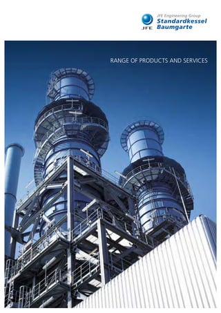
  • 1. RANGE OF PRODUCTS AND SERVICES
  • 2. IDEAS FULL OF ENERGY! As our energy resources grow ever scarcer, it is increasingly essential that we make more efficient use of our existing sources of energy – or find entirely new sources for thermal utilisation. That is why our expertise is in greater demand than ever before. In the following pages, you will find out how we transform ideas into energy. 2
  • 3. Since December 2014 Standardkessel Baumgarte Group belongs to JFE Engineering Corporation. JFE Engineering Corporation, a subsidiary of JFE Holding Inc., is a market leader for „Grate Firing Systems“ and „Gasifying and Direct Melting Furnace Systems“. With more than 350 furnaces installed, JFE Engineering has its main experience in the Japanese market. With regard to biomass power plants, JFE Engineering is specialized on the construction of large sized power plants employing circulating fluidized bed boilers. CONTENT 1 2 3 4 5 6 7 8 COMPANY PROFILE 04 ENERGY FROM WASTE 06 ENERGY FROM BIOMASS 20 ENERGY FROM WASTE HEAT 28 ENERGY FROM PRIMARY FUELS 40 PROCESS TECHNOLOGY 46 PLANTSERVICES FROM A TO Z 62 INNOVATIVE TECHNOLOGIES 66 CUSTOMER REFERENCES 74 3
  • 4. EXPERIENCE IS OUR BEST INVESTMENT. INTELLIGENT SOLUTIONS FOR EVERY FACET OF YOUR ENERGY SUPPLY. There are many ways in which different sources of energy can be transformed into heat, steam and electricity. At Standardkessel Baumgarte we not only know these ways – we also find new ones. Thanks to our more than 160 years of experience, we have incomparable process expertise, regardless of whether it concerns, the supply of high-quality components, the implementation of complete complex systems, the provision of services as an EPCM contractor or the delivery of top-notch plant services. Even new energy concepts such as contracting are becoming increasingly attractive options for many customers. It is therefore no surprise that energy supply companies, municipal governments, public utilities and industrial firms all rely on our know-how in these matters. That is because they know that experience is our best investment. Company Profile 4
  • 5. 5
  • 6. PUTTING RESIDUES TO WORK ENERGY FROM WASTE Fuel Household and household-type industrial waste, production waste, used tyres, blast furnace gas, coke gas, liquid and gaseous industrial waste. Performance range Solid residues up to 140 t/h – 500°C – 100 bar / Liquid, gaseous residues up to 600 t/h – 570°C – 170 bar Boiler technology Steam generator operating in natural circulation with two or three vertically arranged radiation passes and a down­ stream convective pass. The first, second or third boiler pass are in empty pass construction and form the combustion and ­radiation area. The vertical or horizontal convective boiler pass is equipped with the superheater, ­evaporator and economiser convective heating surfaces. All convective heating surfaces can be cleaned with a rapper while in operation. Depending on the profile for requirement, boiler constructions with the installation of 3 or 4 passes can be applied. The temperature of the superheated steam is regulated by a multistage injection cooler between the heating surfaces of the superheater. Combustion system Air or water-cooled pusher-type grate with ram feeder Combustion that is highly resilient both thermally and mechanically with intelligent combustion control. The fuel is metered by a plunger feeder. Every grate zone can be controlled individually, including a multistage primary air distributor. The secondary air is injected via nozzle trays arranged in the first and rear wall of the furnace area. Fluidised bed firing The fuel is fed through openings of the evaporator side walls of the combustion chamber into the fluidised bed. The combustion air and the recirculated flue gas is injected into the fluidised bed and into the combustion chamber at different levels as secondary and tertiary air-injection. Industrial combustion systems for liquid and gaseous fuels Combustion technology for low-NOx industrial and power station combustion systems. The selection and configuration of the burners is performed in accordance with the burner performance within the enclosing walls of the com­ bustion chamber. Fuel gas treatment Reliable compliance with legal emission limits is ensured by a downstream flue gas cleaning system. Quasi-dry, conditioned dry and dry process versions are deployed. Calcium hydroxide Ca(OH)2 , calcium oxide CaO or NaHCO3 are fed into the flue gas as additives for the absorption of the acidic gas components. As an alternative, wet pro­cesses may also be used. The separation of heavy metals and organic substances such as dioxins and furans is performed using adsorption with activated lignite coke or activated carbon. Fabric filters, electrostatic precipitators or cyclones are used to ensure the required particle separation. In particular, the preferred fabric filter not only guarantees minimal dust emissions, but also the lowest concentrations of pollutants in the clean gas thanks to the intensive absorption and adsorption processes in the filter cake. The removal of nitrogen from the flue gases can be performed using either an SNCR (selective non catalytic reduction) process or an SCR (selective catalytic re­duction) process. 1 6
  • 7. The thorough disposal of household waste and household-type industrial waste is still a current issue. The shortage in global energy recources and the increasing concern about our ­environment requires that we direct our attention to this task by ­means of the most innovative plant technology. As a result of the increasing worldwide production of consumer goods, the use of industrial production wastes as an alternative fuel source is also becoming an increasingly attractive option. Standardkessel Baumgarte supplies the necessary systems that will continue to allow for the practical and environmentally friendly utilisation of industrial wastes in future: for efficient energy generation. 7
  • 8. Sources of Energy REFUSE AND WASTE MATERIALS / HOUSEHOLD AND INDUSTRIAL WASTES 8
  • 9. Sample Reference OOSTENDE, BELGIUM Residues The Task To fulfil the task to design a waste to energy plant based on economic parameters with the highest possible efficiency, different plant capacities were examined in close ­coope­ration with the client and the Belgian power supply company Electrawinds Biostoom N. V. The secured amount of fuel was a decisive factor for the maximum plant capacity. The Solution The optimum overall economic solution for the planned pro- ject was found using the basic planning of an already imple- mented boiler type with a relevant high capacity. In the presence of an average fuel throughput of around 17 t/h, the steam generator is capable of producing a volume of steam of approx. 80 t/h at a pressure of 42 bar and a tempe- rature of 400°C. The steam turbine is designed for full con- densing operation. A steam amount up to 19.4 MW can be electrically generated. In close cooperation, Baumgarte Boiler Systems GmbH accompanied the client’s services throughout the entire project. Scope of Supply • Fuel Bunker Crane and Slag Conveying Unit • Pusher Type Grate System incl. Ancillary Equipment • Main Steam Generator with Fittings • Flue Gas Treatment • Refractory Lining and Thermal Insulation • Induced Draught Fan and Steel Stack • Heating Surface Cleaning Devices in Form of Spraying, Rapping and Soot Blower Systems • Ignition and Auxiliary Firing with Fuel Storage and Conveyor Systems • Boiler and Turbine House Steel Structure • Steel Structure for Firing System and Boiler incl. Stairs and Platforms • Water-Steam-Cycle with Turbine, Condenser, Steam Conversion • Electro, Control, Measuring and Process Technology, Low Voltage Technology, Emergency Power Supply Engineering Services • Engineering incl. Approval and Official Engineering • Installation and Commissioning • Trial Run Technical Project Information Number of lines 1 Fuel Domestic/Industrial refuse Heating value (min. / max. / nom.) 11.0 / 18.0 / 15.0 MJ/kg Fuel throughput (min. / max. / nom.) 12.6 / 21.0 / 16.8 t/h Rated thermal input 70.0 MW Steam capacity 80.3 t/h Design pressure 54.0 bar g Steam pressure 41.0 bar g Steam temperature 402°C Feedwater temperature 130°C Fuel gas flow 135,000 m³ i. N./h Exhaust gas temperature 180°C Operating approval Vlarem II Year of commissioning 2009 Example of a plant fired using household and household-type industrial waste 9
  • 10. 10
  • 11. Sample Reference FRANKFURT, GERMANY The Task The waste incinerator technology developed by Baumgarte Boiler Systems GmbH was applied not just when the new waste incineration plant Frankfurt Nordweststadt was built in 1964 but also when it was partly renewed in 1983. Alrea- dy during the offer phase of the second part renewal, which was commissioned in 2004, the general contractor Lurgi Lentjes AG involved us intensively. The task was to develop a waste incineration plant designed for demanding steam pa- rameters in consideration of the latest technologies. In addi- tion, the very restricted space conditions had to be taken into consideration when developing the boiler concept and the increased performance. The Solution Development of a boiler concept designed as a two-pass sys­ tem with furnace area followed by a radiation area in vertical construction and a downstream horizontal pass with the in- stallation of convective heating surfaces. Through this con- cept an increased plant performance by around 35% could be realised by maintaining the existing space conditions. So as to protect the superheaters from corrosion in the presence of main steam temperatures normally unusual in waste inci- neration plants, the heating surface tubes were cladded with the high-grade Inconel material. The plant was renewed in two construction stage, i. e. two lines were revamped in one stage with the other two in full operation. Scope of Supply • Main Steam Generator with Fittings • Heating Surface Cleaning Plant as Mechanical Rapping Device • Heating Surface and Furnace Area Cladding • Steel Structure with Stairs and Platforms • Thermal and Sound Insulation • Refractory Lining Engineering Services • Engineering incl. Approval and Official Engineering • Installation incl. Provision of Lifting Devices • Commissioning and Trial Run Technical Project Information Number of lines 4 Fuel Household waste, house­ hold-type industrial waste Heating value (min. / max. / nom.) 8.0 / 14.0 / 11.0 MJ/kg Fuel throughput each (min. / max. / nom.) 12.0 / 22.0 / 20.0 t/h Rated thermal input each 62.8 MW Steam capacity each 67.2 t/h Design pressure 80.0 bar g Steam pressure 59.0 bar g Steam temperature 500°C Feedwater temperature 130°C Fuel gas flow each 122,500 m³ i. N./h Exhaust gas temperature 220 – 240°C Operating approval 17. BlmSchV Year of commissioning 2006 / 2008 Residues Example of a plant fired using household and household-type industrial waste 11
  • 12. Sources of Energy REFUSE AND WASTE MATERIALS / REFUSE-DERIVED FUELS 12
  • 13. Sample Reference BERNBURG, GERMANY The Task To ensure the supply of energy to the Solvay Company in Bernburg, a second mainstay for energy supply had to be created. The EAB Company, a subsidiary of the waste ma- nagement and recycling specialist Tönsmeier and the phar- maceutical enterprise Solvay planned the installation of a waste-to-energy power plant. On the basis of their powerful references with their conception of identical boiler plants, the Standardkessel Baumgarte Group was able to obtain the order to install three combustion lines with equal perfor- mance rating on a turnkey contract basis. The Solution The well proven technical conception was supplied from one hand source by Standardkessel Baumgarte Group. The deli- very included, but not limited to the furnace area situated above a water-cooled pusher type grate, two vertical radiati- on passes and a vertical economiser was selected for these waste-to-energy combustion lines. The overall scope of order encompasses the fuel supply, feed-water system, instrumen- tation and control engineering, building services enginee- ring, the flue-gas treatment system and the stack. Scope of Supply • Steam Generator with Valves and Accessories • Heating Surface Cleaning System as Spray-Water System, Rapping and Sootblowing Device • Pusher-Type Grate System including Auxiliary Aggregates • Ignition and Auxiliary Firing Systems with Fuel Tanks and Conveying Systems • Fuel Bunker Crane and Slag Conveying Plant • Boiler and Machine Hall Steel Structure, Supporting Structure for the Firing System and Boiler including Stairs and Platforms • Refractory Lining and Heat Insulation • Flue-Gas Cleaning Plant, Forced Draft Fan and Steel Stack • Metrological Boiler Equipment and Building Services Engineering • Instrumentation, Control and Low-Voltage Engineering • Emergency Power Engineering Services • Engineering incl. Approval and Official Engineering • Installation and Commissioning • Trial Run Technical Project Information Number of lines 3 Fuel Domestic/Industrial waste Heating value (min. / max. / nom.) 10.5 / 18.0 / 15.0 MJ/kg Fuel throughput (min. / max. / nom.) 11.3 / 21.0 / 16.8 t/h Rated thermal Input 70.0 MW Steam capacity 80.0 t/h Design pressure 55.0 bar g Steam pressure 41.0 bar g Steam temperature 410°C Feedwater temperature 130°C Fuel gas flow 136,000 m³ i. N./h Exhaust gas temperature 180°C Operating approval 17. BlmSchV Year of commissioning 2010 Residues Example of a plant fired using household and household-type industrial waste 13
  • 14. Sources of Energy SOLID INDUSTRIAL RESIDUES 14
  • 15. Example of a plant fired using solid industrial materials The Task In Hungary, the company TECHCON Környezetvédelmi és Energetikai Szolgáltató Kft disposes used tyres and produc- tion residues from the production of tyres. The accumulating residues, such as car tyres, truck tyres and tyres of heavy ag- ricultural machines shall be disposed of by thermal means and the inherent energy shall be converted into electricity. The accumulating residual substances as a result of incinera- tion as well as flue-gas cleaning, are either to be treated to obtain valuable substances or to be sent to landfills. The Solution TECHCON Környezetvédelmi és Energetikai Szolgáltató Kft placed an order with a Hungarian general contractor for the supply of a power plant on a turnkey basis. The order for the thermal part, consisting essentially of the fuel conveying sy- stem, the steam generator with grate stoker and flue gas cleaning, was secured by Standardkessel. The tyre handling equipment separates and transports the whole tyres from the storage area to the feed device for the firing system. The core of the plant is build up of the underfeed stoker and the vertically arranged natural circulation boiler which generates the superheated steam for feeding into the connected steam turbine. The flue gases are freed of all pollutants in a flue gas cleaning plant, based on the dry sorption process, and are discharged into the atmosphere via a stack after cleaning. Scope of Supply • Tyre Handling System • Firing System • Steam Generator • Flue-Gas Cleaning System • Ancillary Plants • Structural Steelwork, Stairs and Platforms Engineering Services • Engineering incl. Licensing Engineering and Engineering for Official Permits • Assembly and Commissioning • Trial Run Technical Project Information Number of lines 1 Fuel Used tyres Low heating value (min. / max. / nom.) 28.0 / 36.0 / 31.4 MJ/kg Fuel throughput per line (min. / max. / nom.) 2.5 / 3.5 / 2.9 t/h Rated thermal input 25.3 MW Electrical power output 5.6 MW Steam capacity 27.4 t/h Steam temperature 503°C Steam pressure 80 bar g Feedwater temperature 130°C Rated fuel gas flow (nom.) 55,000 m³ i. N./h Fuel gas temperature 220°C Operating approval 17. BlmSchV Year of commissioning 2011 Sample Reference POLGAR, HUNGARY Residues 15
  • 16. Sources of Energy LIQUID AND GASEOUS INDUSTIRAL RESIDUES 16
  • 17. Sample Reference WESSELING, GERMANY The Task Shell Deutschland Oil GmbH operates a power plant at the Wesseling location for supplying the adjacent refinery with electricity and process steam. To fulfil the new environmental guidelines, two old boilers have been set out of operation and the installation of two new boilers has been planned. Standardkessel GmbH was entrusted with the task of cons­ tructing the new boilers No. 7 and No. 8 in order to secure the energy supply to the refinery and to dispose the produc- tion residues. It was particularly important for Shell to meet its energy requirements from its own production residues in order to save primary fuels. The Solution The new boiler No. 7 is mounted on the existing foundations of an old boiler house. The flue gas desulphurisation plant was already provided by the customer for boiler No. 6 and designed for a later extension. Within the scope of the cons­ truction of the new building, the new boiler was connected to the existing flue gas desulphurisation plant. The new boi- ler is designed in vertical construction and operates in natural circulation. The burner system is arranged in the front wall of the boiler’s combustion chamber. Scope of Supply • Steam Generator • Firing System for Liquid and Gaseous Fuels • Air and Flue Gas Ducts • SCR System, Electrostatic Precipitator • Piping • Electrical and Instrumentation and Control Components • Structural Steelwork, Stairs and Platforms Engineering Services • Engineering and Obtaining Approvals / Licences incl. Liaising with Authorities • Delivery, Erection and Commissioning • Trial Operation Residues Technical Project Information Fuel Heavy fuel oil, Production residues (gaseous), Production residues (liquid) Heating value (nom.) 39.53 MJ/kg Fuel throughput rate (max.) 14 t/h Thermal capacity of firing system (max.) 168 MW Steam capacity 200 t/h Steam temperature 520°C Approved working pressure 138 bar Feed water temperature 145°C Waste gas temperature 165°C Operating licence 17. BlmSchV / SVTI Year of commissioning 2012 Example K7 17
  • 18. Sources of Energy COKE OVEN GAS / BLAST FURNACE GAS 18
  • 19. Sample Reference SALZGITTER, GERMANY The Task The steam generator plant covers a part of the supply of electricity and heat for the steel production process of SZFG. Special demands concerning the technical solution were made on high availability, the high quality standard, low emission values and high efficiency with low station service of the plant. The steam generator is integrated into the newly constructed power plant. The Solution The steam generators were designed as radiant boilers of a 2-pass type of construction and arranged suspended in the structural steelwork of the boiler. The firing system is desig­ ned as a frontal firing system with a total of 6 burners. In or­ der to reduce the NOx emissions, a flue gas recirculation sy- stem has been provided. The boiler generates superheated steam and is equipped with a reheater. By means of a heat displacement system involving combustion air, flue gas, feed- water and blast furnace gas / converter gas, optimum opera- tion is achieved with low emission values and a high efficiency. Scope of Supply • Blast Furnace Gas / Converter Gas Fan Station • Heat Displacement System • Combustion Air System incl. Air Preheating • Steam Generators • Structural Steelwork, Stairs and Platforms • Waste Gas System as far as the existing stack Engineering Services • Engineering • Erection and Commissioning • Trial Operation Technical Project Information Fuel Furnace gas / Converter gas Calorific value 3.436 MJ/Nm3 Rated thermal input 250 MW Fuel Coke Oven Gas Calorific value 17.24 MJ/Nm3 Rated thermal input 180 MW Fuel Natural gas Rated thermal input 180 MW Fuel Fuel Oil EL Rated thermal input 150 MW Rated thermal input (total) 298 MW Steaming capacity HP / RH 340 / 320 t/h Steam temperature HP / RH 568 / 563°C Steam pressure HP / RH 168 / 45 bar Feedwater temperature 255°C Flue gas volume flow 451,000 m³ i.N./h Exhaust gas temperature 130°C Operating licence 13. BlmSchV Year of commissioning 2010 Example of a blast furnace gas fired plant Residues 19
  • 20. ENERGY FROM BIOMASS 2Fuel Matured wood, waste wood, fresh wood, forest waste, tree prunings, peat, bark Other bio-fuels such as e. g. rice husks, olive pressing residues, etc. Performance range Steam parameters Pusher type grate system up to 115 t/h – 525°C – 100 bar Travelling grate system up to 160 t/h – 525°C – 100 bar Fluidised bed firing system up to 115 t/h – 525°C – 100 bar Dust burner up to 60 t/h – 525°C – 100 bar Boiler technology Steam generator in boiler systems with natural circulation with several vertically arranged boiler passes. The first and second boiler passes have been designed as open passes and are subdivided into a firing chamber and radiant chamber. The following passes are equipped with ­superheater, evaporator and economiser bundles. All convective heating surfaces can be cleaned by soot blowers during operation. The superheated steam tempe­ rature control is carried out by means of an injection cooler between the superheater heating surfaces. Combustion system Pusher type grate system Fuel-loading is done by a feeding ram under the fuel feeding chute. The primary air is introduced under the grate system. The different air zones can be controlled ­independently from each other. The nozzles for the secondary air injection are located at the front and rear boiler walls above the combustion chamber. Travelling grate Fuel-loading is done by a spraeder stoker system. The primary air is introduced under the grate system. The different air zones can be controlled ­independently from each other. The nozzles for the secondary air injection are located at the front and rear boiler walls above the combustion chamber. Fluidised bed firing The fuel is fed through openings of the evaporator side walls of the combustion chamber into the fluidised bed. The combustion air and the recirculated flue gas is injected into the fluidised bed and into the combustion chamber at different levels as secondary and tertiary air-injection. Flue gas treatment According to the requirements, e.g. following equipments are foreseen: Cyclone system, bag house filter respectivly electrostatic precipitators. Following the emission requirements a flue gas conditioning system can also be foreseen in dry, semi-dry or wet washing processes. Use of SNCR / SCR technology. A MATURE TECHNOLOGY 20
  • 21. Wood has been used to generate heat and energy since time immemorial, yet this environmentally friendly energy source has been growing ever more important since the introduction of the German Renewable Energy Act (EEG). This is true not only in Germany and Europe, but around the globe. In addition to wood, all other biogenic energy sources are in de- mand for environmentally friendly, CO2 -neutral energy generation. ­Standardkessel Baumgarte offers a wide array of applications with which to meet your needs. High costs for primary energy sources such as oil and ­natural gas and, most notably, environmental concerns, have ­created a real boom in the environmentally-friendly generation of ­energy from biomass. 21
  • 22. Sources of Energy WOOD / WASTE WOOD 22
  • 23. The Task At the Eberswalde location a new biomass-fired power plant (BMPP) had to be constructed in the harbour area. The task of the BMPP is to supply the surrounding households with electricity. Moreover, the co‑generation of process steam for supplying the surrounding business enterprises/production plants is planned. As fuel for the BMPP, only fresh wood is used, in accordance with the Biomass Ordinance. The order for implementation was placed with Standardkessel in July 2005. The Solution The delivery of the fuel is carried out by means of trucks. The fuel is taken from the receiving station to a roofed-over out- door storage area where it is put into intermediate storage. From the open air storage area, the fuel is conveyed by ­means of moving floors and conveyor belts to the boiler area. The thermal part consists of grate stoker, steam gene- rator and flue-gas cleaning system. The firing of the fuel is carried out via a three-compartment underfeed stoker. The steam generator is designed as a water-tube boiler in the vertical type of construction with natural circulation. In or- der to achieve optimum efficiency, there is an integral reheat stage. Flue-gas cleaning is carried out in a dry process by means of fabric filters. The electric energy generated in the turbine/generator is fed into the public grid. Scope of Supply Turn-Key Biomass Power Station consisting of: • Fuel Feed System • Firing System / Boiler / Flue-Gas Cleaning System • Water / Steam Circuit with Reheat • Steam Turbine / Generator/ Cooling Tower / Cooling Circuits • Chemical Water Treatment • Electrical Instrumentation and Control System • Auxiliary Plant Units Engineering Services • Engineering incl. Licensing Engineering and Engineering for Official Permits • Assembly and Commissioning • Trial Run Biomass Sample Reference EBERSWALDE, GERMANY Technical Project Information Number of lines 1 Fuel Wood Low heating value (min. / max. / nom.) 8.5 / 12.0 / 10.4 MJ/kg Fuel throughput (min. / max. / nom.) 11.0 / 24.0 / 22.0 t/h Rated thermal input 65 MW Electrical power output 20 MW Steam capacity HP / RH 68 / 68 t/h Steam temperature HP / RH 482 / 472°C Steam pressure HP / RH 82 / 19 bar g Feedwater temperature 105°C Rated flue gas volume 135,000 m³ i. N./h Fuel gas temperature 170°C Operating approval 13. BlmSchV Year of commissioning 2006 Example of a wood-fired plant 23
  • 24. 24
  • 25. The Task On the basis of the Dutch Act for the Promotion of Renew- able Energies‘ (MEP), the company Twence planned the construction of a biomass-fired power station at the location of the waste from waste plant in Hengelo. In the new bio- mass-fired power plant, the percentage of waste wood ob- tained from the waste flows was to be converted into electri- city in an environmentally friendly and efficient way and to be fed into the public grid. The order for the construction of the biomass-fired power plant was placed with Standardkes- sel in October 2005. The Solution The waste wood extracted from the waste flows is delivered and stored in a warehouse. A multistage conveying device conveys the fuel to the boiler. At the same time, metal and oversize material are separated. The thermal part of the plant consists of a multi-lane underfeed stoker, a 4-pass vertical boiler with natural water circulation and a downstream flue- gas purification unit. The flue gas purification unit works on the principle of dry sorption and additionally includes an SCR system for the reduction of the nitrogen oxides. The superhe- ated steam generated in the boiler flows to the turbine/ge- nerator unit and produces electric current that is fed into the public grid. Scope of Supply Biomass Power Station consisting of: • Civil Works • Fuel Transportation System • Grate System • Steam Generator • Flue Gas Treatment Plant • Water-Steam Cycle • Electrical Instrumentation and Control System • Auxiliary Equipment Engineering Services • Engineering incl. Licensing Engineering and Engineering for Official Permits • Assembly and Commissioning • Trial Run Biomass Sample Reference BEC TWENCE, NETHERLANDS Technical Project Information Fuel Waste wood (A1 – A4) Low heating value (min. / max. / nom.) 10 / 16 / 13.4 MJ/kg Fuel throughput (min. / max. / nom.) 10.3 / 22.5 / 19.0 t/h Rated thermal input 73 MW Electrical power output 20 MW Steam capacity 80 t/h Steam temperature 465°C Steam pressure 68 bar g Design pressure 79 bar g Feed water temperature 130°C Rated flue gas volume 111,500 m³ i. N./h Fuel gas temperature 170°C Operating approval BVA Year of commissioning 2007 Example of a wood-fired plant 25
  • 27. Biomass Example of a plant fired using the residue left after pressing olives The Task EL Oleicola El Tejar in Baena, Andalucia, is one of the largest olive oil producers in Spain. Until now, olive waste generated during the production process was disposed of on large waste disposal sites. However, since Spanish legislation en- courages the utilization of regenerative energies, using olive waste for generating electricity in a biomass power plant was found to be advantageous. The Solution Standardkessel has developed the first European biomass po- wer plant capable of using “alperujo”-olive waste generated during the extraction of olive oil in a centrifugation process – as fuel. In December 1998, the contract for development and turn-key construction was concluded between Agroenerge- tica de Baena S.L. and Standardkessel. The start-up, success- ful performance test run and approval took place in February, 2002 – faultlessy and in compliance with all contractually agreed-upon guarantees. Spanish and European legal requi- rements were not only fulfilled, but in terms of emissions, even surpassed in many cases. The maximum electrical out- put is 25 MW. Scope of Supply Turn-key Biomass Power Plant, specifically: • Civil Works • Fuel Storage and Supply, including Diesel Oil Stock as Ignition and Fuel • Steam Boiler with Grate Firing • Flue Gas Purification • Steam Turbine • Water Treatment / Waste Water Treatment • Cooling and Condensation System • Required Systems such as Water/Steam Cycle, Pressurized Air System, Fire-Fighting System • Control System, Electrical and Lightning Equipment Engineering Services • Engineering incl. Permit and Authority Engineering • Erection • Commissioning Sample Reference BAENA, SPAIN Technical Project Information Number of Lines 1 Fuel Olive waste Low Heating Value (min. / max. / nom.) 9.2 / 15.1 / 10.1 MJ/kg Fuel throughput (min. / max. / nom.) 25.0 / 41.0 / 37.4 t/h Rated thermal input 105 MW Electrical power output 25 MW Steam capacity 110 t/h Steam temperature 455°C Steam pressure 78 bar g Feed water temperature 105°C Rated flue gas volume 161,890 m³ i. N./h Fuel gas temperature 160°C Operating approval EU Requirements Year of commissioning 2002 27
  • 28. A HOT TOPIC HEAT RECOVERY Heat source Gas turbine exhaust gas Performance Range Steam parameters up to 600 t/h – 570°C – 170 bar Auxiliary fuels Coke oven gas, blast furnace gas, natural gas, light oil, production exhaust gases Boiler technology Steam generators with natural circulation in horizontal or vertical one or multi-pass construction with different pressure stages. Either designed as heat recovery boiler or equipped with auxiliary firing also suited for fresh air ­operation and „flying takeover“ between fresh air operation mode and gas turbine operation mode. The superheat steam temperature control is carried out by means of an injection cooler between the superheater heating surfaces. Combustion ­system Industrial combustion systems as duct burners in the gas turbine exhaust duct or as in-duct burner in the combus­ tion chamber of the boiler plant respectively or in conventional burners with an external exhaust gas feed. 3 28
  • 29. In many industrial production processes, the energy consumption ratio is continuously rising. No surprise then, that „­efficiency boosting“ is increasingly becoming the focus of ­production process design. The heat recovery steam generator (HRSG) downstream a gas turbine is of decisive importance for ensuring the efficient utilisation of the energy from the gas and steam turbine process. It utilises the turbine exhaust to generate steam, and is usually also equipped with an additional firing system in order to increase the overall efficiency of the system. In addition, HRSGs that have been designed for the “flying takeover” also deliver high operational reliability and availability. These boiler systems can be opera- ted in both GT exhaust gas and fresh air modes. The system switches between operating modes automatically without any adverse effect on the steam turbine operation. 29
  • 30. Sources of Energy GT PROCESS 30
  • 31. Waste heat Sample Reference LINDEN, GERMANY Example of a HRSG The Task The heat recovery steam generator (HRSG) is fitted into an existing boiler house in which a coal-fired boiler was previ- ously installed. Then, together with the existing No. 1 waste heat boiler, a common steam range will be used which feeds to a new steam turbine having a reheating system. The tur- bine is intended to be operated in efficient variable pressure operation, so the boiler and the steam lines will be designed in such a way that in the event of the failure of No. 1 waste heat boiler the new boiler can produce its full capacity even at half the pressure. For the most flexible use possible, in particular with widely varying load requirements, the boiler is designed for fast start-up. Due to the long delivery time of the steam turbine, for economic reasons it is planned to start bypass operation already during the erection phase. The Solution In order to meet these requirements, Standardkessel is supp- lying a vertically arranged natural circulation boiler with an additional condensate heat exchanger which also feeds the district heat supply system. Besides the HP and the MP parts, the boiler is also provided with a reheater to optimize effici- ency. The steam generator is constructed as a suspended boiler and designed in such a way that the existing steel sup- porting structure of the old coal-fired boiler can continue to be used. For the generation of peak current with waste heat operation, the plant is equipped with a flue gas bypass for 100% flue gas flow. The waste gases from No. 2 waste heat boiler and/or bypass flow into a joint stack. Scope of Supply • 3-Pressure HRSG with Condensate Heat Exchanger • Flue Gas-Bypass Duct incl. Dampers • Supplementary Steel Structure, Stairs and Walkways • Auxiliary Equipment Engineering Services • Approval Engineering • Planning and Execution Engineering • Assembly • Commissioning Technical Project Information Energy source GT-exhaust gas Type of gas turbine GE 6 FA Fuel for auxiliary firing – Electrical power output GT 77 MW GT-flue gas flow 215 kg/s GT-exhaust gas temperature 590°C Steam capacity HRSG HP / RH / MP / LP 93 / 104.6 / 12.8 / 11 t/h Steam Temperature HP / RH / MP / LP 540 / 544 / 351 / 240°C Design Pressure HP / RH / MP / LP 98.1 / 29 / 31 / 5.2 bar HRSG-exit gas temperature 80°C Year of commissioning 2011 31
  • 32. 32
  • 33. The Task The increased production capacity owing to the installation of an additional paper machine also required a performance boost on the part of the power center. The demands on en- ergy supply within a paper and cardboard company – high electric capacity paired with high steam consumption – had to be taken into consideration where an enlargement of the plant by means of a new steam generator was concerned. In addition, the requirements for high dynamic load follow- ing capabilities (load changes up to 1 MW/s) had to be met and the boiler’s part load performance at 100% turbine out- put was to be optimised. The concept of a combined heat and power plant was again to be realized by using the patented CHPP SYSTEM HUTTER which had been patented by the ­company Friedrich Hutter GmbH. The Solution A natural circulation boiler with generous internal piping and supply lines was to be conceived in order to meet the targets. This led to a stable internal circulation as well as to the main- tenance of the required dynamics. A process steam cooler was implemented in the flow-oriented turbine exhaust duct – totally in line with demands of the patented system. Scope of Supply • Steam Generator with Valves • External process steam cooler in the exhaust Gas Duct • Ripped-Tube Economiser • Refractory Lining of Burner Muffles • Boiler Feedwater System • Feedwater Tank Engineering Services • Engineering • Installation and Commissioning • Trial Run Sample Reference VAREL, GERMANY Technical Project Information Number of lines 1 Fuel Natural gas H Heating value 31.66 MJ/m3 i.N. Fuel throughput 6,078 m3 i.N./h Rated thermal input 53.46 MW Combustion air Gas turbine exhaust gas as oxygen carrier GT-exhaust gas temperature 556°C GT-exhaust gas volume flow (wet) 41.76 kg/s Steam capacity 90 t/h Design pressure 105 bar g Steam pressure 89 bar g Steam temperature 480°C Feed water temperature 105°C Exhaust gas temperature 135°C Design code TRD-DIN / EN Year of commissioning 2007 Example of a boiler plant Waste heat 33
  • 34. 34
  • 35. Sample Reference PLATTLING, GERMANY The Task Kraftwerk Plattling GmbH, a subsidiary of E.ON Energy Pro- jects, constructed at the location of the paper mill of the Myllykoski Group in Plattling a CHP power plant as a com- bined gas and steam turbine plant. The power plant is inten- ded to ensure that the adjoining paper mill is supplied with process steam as well as with electric energy by means of cogeneration. Standardkessel was given the task of construc- ting the heat recovery boiler for fully automatic and econo- mical continuous operation at high efficiency and availability, with at the same time maximum reliability of the steam sup- ply being achieved. The Solution In order to solve the problem Standardkessel is supplying a heat recovery boiler of horizontal construction. The heat re- covery boiler in the power plant in Plattling is operated downstream of a GE 6FA gas turbine with an approx. 60 MW auxiliary firing system and a cooled combustion chamber. At full load, the HRB reaches a steaming capacity of 201 t/h at a steam pressure of 92 bar and a steam temperature of 532°C. The gas and steam turbines together generate up to 110 MW of electricity, the process steam being taken off at a low stage from the pass-out condensation turbine. Besides the heat recovery boiler, Standardkessel is supplying the as- sociated steelwork, the flue gas duct between the gas turbi- ne and the heat recovery boiler, the silencer and the stack as well as the field instrumentation and the complete burner control system. Scope of Supply • Single-Pressure HRSG with Condensate Heat Exchanger • Auxiliary Gas Firing System • Structural Steelwork, Stairs and Platforms • Ancillary Plants • Stack • Silencer Engineering Services • Work of Obtaining Approvals / Licences • Planning and Design Engineering • Erection • Commissioning Technical Project Information Energy source Natural gas Gas turbine type GE 6 FA Additional tuel Natural gas Electrical output of GT 77 MW GT-Exhaust gas flow rate 214.5 kg/s GT-Exhaust gas temperature 592°C HRB steaming capacity 201 t/h Steam temperature 532°C Approved working pressure 108 bar HRB waste gas temperature 110°C Year of commissioning 2010 Example of a boiler plant Waste heat 35
  • 36. Sources of Energy WASTE HEAT FROM INDUSTRIAL PROCESSES 36
  • 37. Sample Reference GROVEHURST, GREAT BRITAIN The Task So as to reduce environmental impact caused by land-filling and land-spreading of the produced waste-paper sludges from the paper making process at Kemsley and Sittingbourne site, a new combustion plant was planned to be built. The energy company E.ON UK commissioned the companies Lurgi Envirotherm GmbH and Lurgi UK with the installation of a fluidised bed combustion plant containing a waste-heat steam generator situated next to the existing power plant at Kemsley Paper Mill. During the early conceptual design phase, Baum- garte Boiler Systems was already involved in the preparation of a concept tailored to build a waste-heat recovery system. The Solution The experience gained from supplied and operative waste- heat recovery systems in comparable applications was the basis of the boiler to be engineered. When the flue gases leave the combustion chamber, they are directly conveyed to the main-steam generator in vertical design with the installa- tion of evaporator walls, superheater and evaporator heating surfaces. The economiser heating surfaces are located in the second flue-gas pass made form sheet-metal casing. So as to provide cleaning of the heating surfaces, both passes are equipped with a steel shot cleaning system and also offers the option to retrofit a soot-blower system. Scope of Supply • Main-Steam Generator with Shut-Off and Control Devices • Boiler Supporting Structure including Stairs and Platforms • Steam Air Preheater • Interconnecting Piping • Cleaning System as Steel Shot Cleaning Plant • Boiler Feed-Water Pumps with Fittings • Blow-Down Tank and Sampling Station • Metrological Boiler Equipment Engineering Services • Approval and Official Engineering • Detail-Engineering and Technical Handling • Erection, Commissioning and Trial Run Technical Project Information Number of lines 1 Fuel Waste heat from sludge combustion Flue gas flow (moisture) 79,400 m3 i. N./h Quantity of flue gas heat 33.75 MW Flue gas temperature 860 – 1000°C Steam capacity 38.8 t/h Steam pressure 26.5 bar g Steam temperature 345°C Feed water temperature 105°C Exhaust gas temperature 160 – 180 °C Air rate 45,000 m3 i. N./h. Air temperature inlet / outlet 25 / 220°C Operating approval BS / EN Year of commissioning 2002 Example of a plant fired using the heat recovered from industrial processes Waste heat 37
  • 38. 38
  • 39. Sample Reference DUNKIRK, FRANCE The Task Gaz de France placed an order with Alstom Power as the general contractor for the construction of a combined gas and steam turbine plant in the French city of Dunkirk. Within the scope of the project, Standardkessel was entrusted with the task of developing a solution for the power station mode of operation of the gas and steam process using a fuel/elec- tricity management system. The two combined gas and steam turbine power plant lines are to generate, at full load, 2 x 400 MWel. The Solution The power plant mode of operation of the combined gas and steam turbine process with a fuel/electricity management sy- stem, which is unique world-wide, was made possible by the special design of Standardkessel‘s special heat recovery steam generator. Unlike the otherwise usual mode of operation of combined cycle gas and steam turbine plants, in the case of this power plant, the major share of the electricity is genera- ted by the steam turbines. The gas turbines are switched on and off fully automatically each day. For the unusual new mode of operation, a special heat recovery steam generator had to be developed. The smooth change-over between gas turbine and fresh air operation with the fuels coke-oven gas and blast-furnace gas requires a flexibly responding boiler with change-over devices which are not only based on the company‘s many years of design experience, but as regards their size and number are unique throughout the world. The boiler plant is designed in a suspended vertical type of construction and is arranged in natural circulation. The bur- ners are of staggered opposed arrangement as a so-called ‚combed‘ opposed firing system. The delivery time for the en- gineering, manufacturing, and erection of both boilers was 26 months. Scope of Supply • Boiler Plant • Firing System for: Coke Oven Gas, Blast Furnace Gas, Natural Gas • Flue Gas Ducts incl. Flaps and Dampers • Stack • Auxiliary Equipment Engineering Services • Engineering • Assembly • Commissioning Technical Project Information Energy source GT exhaust gas Fuel for auxiliary firing Coke oven gas, Blast furnace gas Natural gas Electrical power output GT 2 x 160 MW Electrical power output ST 2 x 240 MW Steam capacity HP / RH 535 / 530 t/h Steam temperature HP / RH 566 / 566°C Steam pressure HP / RH 144 / 31 bar g Feed water temperature 105°C Nominal waste gas flow 536 kg/s GT-Waste gas temperature 527°C RTO Aux. firing system 345 MW FG Temp boiler outlet 120°C Year of commissioning 2004 Example of a plant fired using the heat recovered from industrial processes Waste heat 39
  • 40. ALL FIRED UP ENERGY FROM PRIMARY FUELS4Fuel Coal and lignite briquette, lignite dust, natural gas or fuel oil Performance range Steam parameters Travelling grate firing system up to 160 t/h – 540°C – 140 bar Dust firing system up to 350 t/h – 540°C – 140 bar Gas and oil firing system up to 600 t/h – 570°C – 170 bar Boiler technology This natural circulation steam generator boasts a compact structure and is largely prefabricated in the workshop. As a natural circulation two-drum boiler, prefabricated as a modular system. Steam generators with natural circulation with several boiler passes being vertically arranged. The first boiler pass is formed as open pass and is divided into furnace and radiation chamber. Superheater, evaporator and economiser convection heating surfaces are installed in all further boiler passes. All convection heating surfaces can be cleaned during operation with soot blowers. The superheated steam temperature control is carried out by means of an injection cooler between the superheater heating surfaces. Combustion system Coal, lignite Travelling grate firing with hopper feed and fuel bed controller. The primary air is fed underneath the grate - divided into several separately controllable zones. The secondary air injection is carried out via nozzle rows in the front and rear wall of the furnace. Lignite dust Low NOx industrial/powerstation firing systems are used for lignite dust. The burners are arranged ­depending on the capacity in the surrounding walls of the combustion chamber. Gas, Oil Low NOx industrial/powerstation firing systems as single-fuel system or as combined burner for gas and oil. Fuel gas treatment According to the requirements, e.g. following equipment are foreseen: cyclone system and electrostatic precipitator, SCR or SNCR system. 40
  • 41. We can’t do without them: oil, natural gas and coal still rank among the most important energy sources. Regardless of whether it be anthracite or lignite, coal is a fuel that conti- nues to be an important alternative – not least due to continually increa- sing oil and gas prices worldwide. Price stability and security of supply are often decisive reasons for investing in coal-fired power plants. In spite of increasing energy and fuel prices around the globe, oil and gas continue to be in high demand as fuels. High operational reliability and key factors such as its quick-start characteristics and load-change rates are often key arguments for choosing gas-fired and/or oil-fired boiler systems. 41
  • 43. Sample Reference JÜLICH, GERMANY The Task At Pfeifer Langen’s location in Jülich, the company ope- rates its own power plant for the energy supply. As the exi- sting plants were no longer able to meet the power require- ments of the sugar mill and in addition had become very maintenance and repair-intensive, the decision was taken to modernize the CHP plant. With the new plant a long-term, sustainable and, from a business management point of view, optimum energy supply was to be achieved by means of low fuel costs as well as the reduction of personnel and opera- ting costs. Moreover, the new CHP plant was required to show, besides a high degree of reliability and availability, a future-orientated technical conception. The Solution To expand the plant’s own energy supply, Standardkessel re- ceived the order from the Jülich works of Pfeifer Langen for the supply of a steam generator including a flue gas clea- ning system arranged downstream. The natural circulation boiler is equipped with a travelling grate stoker firing system and designed for the combustion of bituminous coal, lignite briquettes and fuel oil. In accordance with the CHP principle, the superheated steam is initially used for electricity genera- tion and then as process steam. The plant went into operation in September and already supplied the energy for the sugar beet campaign in the autumn of 2004. Scope of Supply • Coal Handling System, incl. Bunker • Traveling Grate System • Combustion Air System • Steam Generator • Steel Structure • Cyclone • Bag House Filter • Flue Gas Conditioning System • Slag and Ash Handling System Engineering Services • Engineering and Supply • Erection and Commissioning • Putting in to Operation Technical Project Information Number of lines 1 Fuel Lignite briquettes Low heating value 19.8 MJ/kg Fuel throughput 21.8 t/h Fuel Bituminous coal Low heating value 28.6 MJ/kg Fuel throughput 15.1 t/h Thermal input 120 MW Steam capacity 130 t/h Steam temperature 520°C Steam pressure 109 bar g Feed water temperature 110°C Rated flue gas volume (nom.) 168,500 m3 i.N./h. Flue gas throughput 150°C Operating approval 13. BlmSchV Year of commissioning 2004 Example of a coal-fired plant Primary fuels 43
  • 44. Sources of Energy GAS AND OIL 44
  • 45. Primary fuels Sample Reference TRINIDAD, TRINIDAD AND TOBAGO Example of a gas- and oil-fired plant The Task To ensure the generation of steam in the world’s largest me- thanol plant, the PROMAN Gesellschaft für der Projektma- nagement mbH commissioned Baumgarte Boiler Systems GmbH with the planning and delivery of a natural gas-fired packaged boiler system. The specific requirement was to en- sure the continuous operation of the plant during the first three years. After five years of successful plant operation, Baumgarte was awarded the contract to supply a second boiler unit as part of the intended expansion of production capacities. In addition to natural gas, the three burners shall be capable of burning the fusel oil resulting from the produc- tion process. In all other aspects the equipment on order re- mained almost unchanged. The Solution So as to comply with the set conditions, the packaged steam generator was to be conceived as a single-drum boiler. In particular, the steam drum and the evaporator system toge- ther with the headers and distributors were calculated to match the requirement. Apart from the boiler pressure part itself, the major parts of the equipment component were largely designed for redundancy. So, e. g. the combustion air fan was equipped with two independent drives, i. e. electro motor and turbine drive. The control fittings were equipped with quick-acting drives. Scope of Supply • Main-Steam Generator with Fittings • Natural-Gas Firing Plant with Combustion Air System • Steam Turbine Drive for Combustion Air Fan • Steel Structure for Stairs and Platforms • Economiser • Flue-Gas Ducts • Thermal Insulation • Chimney Engineering Services • Engineering • Supervision for Erection • Commissioning Technical Project Information Number of lines 1 Fuel Natural gas / Fusel oil Heating value 35.9 MJ/m3 i.N. Fuel troughput 11.525 m3 i.N./h. Rated thermal input B1: 115.0 MW B2: 114.0 MW Steam capacity 147.5 t/h Design pressure 34.0 bar g Steam pressure 28.5 bar g Main-steam temperature 341°C Feed water temperature 109°C Exhaust-gas temperature 200°C Design regulation TRD-DIN / EN Year of commissioning B1: 2004 B2: 2011 45
  • 46. PROCESS TECHNOLOGY SOLUTIONS ALL AROUND WASTE GAS, EXHAUST AIR AND FLUE GAS CLEANING5Condensation With a high pollutant and/or solvent concentration in the waste gas, consideration is given primarily to recovering the pollutants or solvents as valuable substances in order to save raw materials, energy and costs. A tried and proven process is that of condensation. Depending on requirements and the particular application it is used for emission reduction, recovery and waste gas conditioning as an independent or multistage measure e.g. in combination with a fine cleaning system arranged downstream. Condensation is a thermal separation process in which the waste gas stream containing pollutants and/or solvents cools down to a temperature below the dew point of the compounds. The condensate forming is collected directly in a utilisable form. Depending on the demands made on the condensate, the product recovered can be fed back directly into the process. This is particularly advantageous in the case of applications in such areas of use as coating plants, circulating gas dryers, fixed-bed drying, film coating, chemical and pharmaceutical process engineering, tank farms, gas displacement and respiratory gas. Here, direct condensation is specifically used. Catalysis The catalytic process lends itself to waste gas, exhaust air and flue gas cleaning. The pollutants are converted by oxidation or reduction, if necessary with the use of an additive. Catalytic processes are usually characterised by lower reaction temperatures than in the case of comparable thermal processes. This permits more efficient process control with a considerably reduced energy input. The catalytic process is exothermic. Depending on the case of use and the level of pollutant loading, the heat is recovered via recuperation or regeneration. For the respective specific application – for the initiation of and support for the reaction – various stable and highly active catalysts are used. The pollutants are converted on the surface of the catalyst with a further chemical element or a compound. This element or compound is either present or has to be added. With the use of tried and proven catalysts, reliable adherence to the statutory emission values is ensured. Combined processes When considering individual emission reduction measures, it is to be taken into account that waste gas streams can often no longer be cleaned in an ecologically meaningful manner by means of a single-stage cleaning process. With regard to the constituents and their concentration in the waste gas, mostly further process stages arranged upstream and/or downstream, which are to be regarded as supplements, are to be used. It is likely that official requirements will demand a combination of processes as a solution. 46
  • 47. Now as ever, environmental protection is a big, topical subject for Standardkessel Baumgarte. In this connection an important objective is to develop sustainable concepts for the reduction and avoidance of pollutants. Here Standardkessel Baumgarte provides a wide range of sustainable solutions in the form of product-integrated environmental protection. With integrated and customised concepts, a high level of protection is to be achieved for the environment, resources are to be handled sparingly and emissions are to be avoided, reduced or changed into a usable form. The legislator therefore demands that a cleaning unit be arranged down- stream of the production area or of other emission sources. Standardkessel Baumgarte provides various processes for emission reduc- tion and elimination. With the single-stage or multistage processes and process technologies for waste gas, exhaust air and flue gas cleaning, with the meeting of our high quality standards, the emission limit values required can be complied with and accompanied by optimum energy utilisation and high availability. 47
  • 48. 48
  • 49. Solvent-based Exhaust Gas Cleand Gas Condensate Chiller Unit Heat Exchanger Circulating Pump Spray Cooler Tank Process technology CONDENSATION SPRAY COOLER Direct Condensation of Solvent in a Liquid Jet Direct condensation in refrigerated solvent jet The Task In the production of free-flowing granules, solvents (VOC) are released during their drying. The emission of the solvent concentration is to be reduced and to be put into a form that can be utilised. With a product-integrated concept, the sol- vent used is to be recovered with a high degree of purity by means of suitable measures and to be recycled by means of being returned to the process. The technical rules, especially of explosion protection, must be mandatorily observed. The Solution To minimise the investment costs, the dryer is operated in a closed circuit (circulating air). To reduce emissions and to re- cover solvent provision is made for feeding merely a small part of the main flow via a condenser system. The separation of the solvent and the cleaning of the part flow are carried out by means of direct condensing in a spray cooler in the refrigerated solvent jet. The circulated solvent jet drives the spray cooler and feeds the part flow through the condenser system due to the ejector effect. The part flow cools down to the condensing temperature and the solvent is condensed. Through the recovery, the solvent is removed from the pro- cess and can be reused directly. The solvent-reduced flow is passed back into the main flow. Scope of Supply • Liquid storage tank with ejector tower, self-priming • Circulation pump including piping system • Heat exchanger for indirect cooling of the liquid circuit • Cooling unit • Instrumentation and system control Engineering Services • Engineering • Production and delivery • Erection, commissioning and service Technical Project Information Waste gas flow rate 300 kg/h Waste gas temperature 120°C at inlet Condensation temperature –15°C Condensation capacity 20 kW Liquid circulation flow rate 16,000 kg/h Service pressure Atmospheric Recovery rate based 90% on the incoming load Mode of operation Continuous 49
  • 50. 50
  • 51. CONDENSATION BATH COOLER Direct Condensation of Solvent in a Liquid Bath Solvent-loaded Exhaust Gas Cleaned Exhaust Gas Tank with Liquid Bath Chiller Unit Condensate Storage Tank Fan Direct condensation of solvent in a refrigerated liquid bath The Task For high pollutant and/or solvent concentrations in the waste gas from a production plant, a suitable separation process is to be used for the separation of the solvents and/or the pol- lutants. As a function of the emitting process and depending on the production step, the waste gas is laden with solvents, plasticisers, fuels and propellants, oils, aromatic compounds or paraffin. The solvents are to be recovered as a recyclable material. For further use, the solvents are to be available directly in a liquid form. The Solution To recover and separate the solvents direct condensation in a liquid storage cooler is provided for as a thermal separation process. In this case it is a bubble column in which the evap- orator package built into a tank cools down the liquid in the tank. The liquid corresponds as a rule to the composition of the condensate from the waste gas stream. The waste gas stream to be condensed is fed into the tank via a perforated plate and, as a bubble column, it is conveyed through the li- quid storage tank with the help of a fan. The waste gas con- taining solvent cools in the bubble column to the tempera- ture set in the storage vessel below the dew point of the compounds. The condensate forming is collected directly in the liquid. The liquid storage vessel cooler is kept constantly at the condensation temperature selected. The solvent con- centration at the outlet from the system corresponds to the saturation concentration of the solvent used. Advantages of the System • Low tendency to ice over, no misting • Plasticisers/paraffins contained in the waste gas are largely dissolved and are separated • No deposits at all are built up • The liquid storage vessel cooler constantly cleans itself • Heat exchange takes place directly and with optimum efficiency Scope of Supply • Condensing equipment including fan for waste gas conveying • Evaporator package for cooling the liquid storage vessel • Cooling unit • Instrumentation and equipment control system Engineering Services • Engineering • Production and delivery • Erection, commissioning and service Technical Project Information Throughput rate 20 to 1,700 Nm3 /h Waste gas temperature 0°C to 80°C at inlet Condensation temperature 10°C to  –45°C Service pressure 0.85 to 10 bars Condensation power Up to 70 kW Mode of operation Continuous/discontinuous Solvent concentration 0 to 100% solvent saturation (fluid) Control range, 0 to design volume flow rate volume flow rate (0–100%) 51 Process technology
  • 52. 52
  • 53. Catalytic exhaust air cleaning plant with recuperative heat recovery The Task In a chemical/pharmaceutical production plant, exhaust air containing pollutants that contain volatile organic compounds (VOCs) is emitted. Due to the operational mode of the pro- duction plant markedly fluctuating, exhaust air quantities and different VOC concentrations are released. At a low oxidation temperature the exhaust air is to be cleaned according to the emission limit values set out by the German Air Pollution Control Regulations (TA-Luft) before it is discharged into the ambient air. The Solution For safe and environmentally friendly removal of the volatile organic compounds (VOC), a catalytic exhaust air cleaning plant is used. The plant is able to respond both to the fluc- tuating exhaust gas quantities and to the different concen- trations. As a result of the use of the catalyst, the oxidation temperature – adapted as required – for the conversion of the organic compounds is lowered in comparison with thermal oxidation. Catalytic reaction is exothermic and releases thermal energy during catalytic oxidation. With the use of a highly efficient heat exchanger, auto-thermal operation becomes possible due to heat recovery already taking place at low VOC concentrations. Recuperative heat recovery takes place in order to ensure reliable separation of exhaust air and clean air. Scope of Supply • Fan for conveying the exhaust air stream • Reactor with catalyst material • Heat exchangers for recuperative preheating of the exhaust air stream • Heating equipment designed as burners • Instrumentation and plant control system Engineering Services • Engineering • Production and delivery • Erection, commissioning and service Technical Project Information Exhaust air volume flow rate 5,000 Nm3 /h Exhaust air temperature 30°C Pollutant concentration 2–10 g/Nm3 (VOC) Clean gas value 20 mg/Nm3 VOC Auto-thermal operation from 3 g/Nm3 VOC concentration of Installed burner output 200 kW Service pressure Atmospheric Operating mode Continuous CATALYTIC OXIDATION (CatOx) with recuperative Heat Recovery 53 Heat Exchanger Fan Air Heater Combustion Air Reactor Catalyst Clean Air Clean Air Bypass Polluted Air Natural Gas Start-up-air Process technology
  • 54. 54
  • 55. Catalytic exhaust air cleaning system with regenerative heat recovery The Task Granule storage containers emit, due to subsequent evap­ oration, exhaust air containing pollutants and low hydrocar- bon concentrations. The exhaust air is to be cleaned at a low oxidation temperature according to the emission limit values set out by the German Air Pollution Control Regulations (TA-Luft), before it is discharged into the ambient air. To mini- mise the demand for secondary fuel, auto-thermal operation is to be achieved at low initial concentrations. The Solution For reliable and environmentally friendly removal of the hydro- carbons a catalytic exhaust air cleaning plant with regenerative heat recovery (RCO) is used. Due to the use of the catalyst, the oxidation temperature for the conversion of the organic compounds – adapted as required – is lowered in comparison with thermal oxidation. The catalytic reaction is exothermic and releases thermal energy during oxidation. Through the use of the highly efficient regenerative heat recovery, auto- thermal plant operation is possible without auxiliary heating already at very low pollutant concentrations. Scope of Supply • Fan to convey the exhaust air stream • Two-bed reactor, with catalyst and heat transfer material per bed • Heating system installed between the beds • Instrumentation and plant control system Engineering Services • Engineering • Production and delivery • Erection, commissioning and service Technical Project Information Exhaust air volume flow rate 10,000 Nm3 /h Exhaust air temperature 30°C Pollutant concentration 0–2 g/Nm3 (hydrocarbon) Clean air value 20 mg/Nm3 org C Auto-thermal operation from 0,7 g/Nm3 a hydrocarbon concentration of Heating system Gas-fired burner Installed burner output 250 kW Service pressure Atmospheric Mode of operation Continuous 55 CATALYTIC OXIDATION (RCO) with regenerative Heat Recovery Natural Gas Combustion Air Catalyst Heat Carrier Reactor 1 Reactor 2 Stack Solvent-loaded Exhaust Gas Start-up-air Fan Clean Air Air Heater Hot Bypass Process technology
  • 56. 56
  • 57. Selective Catalytic Reduction Tail end SCR with heat transfer system and steam/gas pre-heater The Task In a combustion plant, nitric oxides (NOx ) are obtained during the combustion process at high temperatures due to oxidation of the nitrogen in the combustion air and oxidation of the nitric oxide bound in the fuel and the liquid residue. The re- quired NOx emission limitation cannot be achieved by means of primary operating measures, so that a suitable secondary measure for emission reduction has to be applied. Due to the high NOx flue gas concentration, an NOx reduction degree of at least 95% is necessary to limit the emissions to the appli- cable clean gas value. The Solution With reference to the stipulation of the high denitrification capacity the SCR process (catalytic flue gas denitrification) is to be applied. The nitric oxides react in an oxidising atmos- phere in the presence of ammonia (NH3 ) to form molecular nitrogen and water. For that purpose the reductant (NH4 OH) is injected into the flue gas duct before the catalyst and ho- mogeneously distributed. Catalytic materials reduce the activa- tion energy of the chemical reaction so that the NOx reduc- tion can, due to the presence of the catalyst, take place at low temperatures. The SCR catalyst is installed at the end of the flue gas cleaning chain as a high-temperature vari- ant. The advantage of this is the simultaneous separation of dioxins and furans. Scope of Supply • Tail end SCR with heat transfer system • Instrumentation and plant control system Engineering Services • Engineering • Production and delivery • Erection, commissioning and service Technical Project Information Exhaust air volume flow rate 150,000 Nm3 /h Flue gas temperature 155°C Pollutant concentration (NOx ) 1,000 mg/Nm3 Clean gas value 70 mg/Nm3 VOC SCR service temperature 250°C Service pressure Atmospheric Mode of operation Continuous 57 SELECTIVE CATALYTIC REDUCTION (SCR) with recuperative Heat Recovery SCR Reactor Blender 2 Blender 1 Compressed Air NH4 OH High-Pressure Steam Condensate Steam-Heated Gas Pre-heater Gas-Gas- Heat Exchanger Exhaust Gas Cooler Clean Gas Condensate Flue Gas Catalyst Process technology
  • 58. 58
  • 59. Two-stage Condensation Direct condensation in a liquid bath – with a spray cooler arranged upstream – in a closed system The Task Wrapped in a paper coating, plant solvents are vaporised in an inert atmosphere in a gas-tight dryer. The plant works at a drying temperature of 120°C. The heated-up air is blown via a primary gas circuit onto the paper web to be dried. At the inlet and the outlet of the dryer, air locks are installed which largely prevent the ingress of air. The primary circula- ting gas flow inside the dryer – with the help of the fans – leads the heat of evaporation to the paper web to be dried. The solvent concentration in the primary circuit is to be red- uced to the equilibrium necessary and admissible for the drying process while the solvent is being recovered. The dryer exhaust gas contains, besides solvents, traces of phenolic re- sins and dust. The Solution To reduce the solvent concentration, the solvent-laden waste gas is extracted by suction via a fan in a secondary circuit. The exhaust gas is pre-cooled in a spray cooler operating with circulating solvent which is cooled in a condensation system. Here, a part of the contamination is bound and a part of the phenolic resin is dissolved. In the condensation system, the gas is reduced to the necessary equilibrium con- centration to then be fed back to the dryer. The phenolic resin particles entrained in the circulating gas flow of the dryer (which have already partly been cracked) and the dust make special demands on the condensation system. The special type of construction of direct low-temperature con- densation is unrestrictedly suitable for these problems. The recovered solvent is separated from the dust in the separator. Scope of Supply • Spray cooler with circulation pump • Condensation equipment with integrated evaporator package • Indirect cooling of the liquid circulation • Cooling unit • Instrumentation and plant control system Engineering Services • Engineering • Production and delivery • Erection, commissioning and service Technical Project Information Waste gas volume flow rate 600 Nm3 /h Waste gas temperature 120°C at inlet Solvent concentration Up to 250 g/Nm3 Condensation temperature –10 °C Condensation power 65 kW Condensate flow rate 120 kg/h Concentration at the outlet 38 g/Nm3 of the condenser system Circulation dryer 4,500 kg/h Service pressure Atmospheric Mode of operation Continuous 59 COMBINED PROCESS Two-stage Condensation Clean Gas Drying Plant Chiller Unit Condensate Storage Tank Pump Spray Cooler Tank with Liquid Bath Fan Process technology
  • 60. 60
  • 61. The Task In a chemical multipurpose plant, a waste gas laden with hydrocarbons is emitted at different volume flow rates and time intervals from various sources. The waste gas is to be cleaned using an economically flexible process before it is discharged into the ambient air. In order to save raw ma- terials, energy and costs, the solvents are to be largely recovered as valuable resources and to achieve the appli- cable emission limit values, to be treated in a further pro- cess stage at a low oxidation temperature. The Solution Cleaning is carried out in two process steps. The first stage is direct condensation of solvents in a liquid bath. By means of condensation a residual concentration remaining almost constant is achieved. The concentration achieved corre- sponds to the saturation conditions of the solvent used and/or of the composition of the bath. Concentration peaks are thus reduced. This remaining residual concentra- tion is cleaned to the applicable emission limit values in a second cleaning stage designed as a catalytic exhaust air cleaning system with a recuperative heat recovery system. Scope of Supply • Low-temperature condensation - Condensation unit including fan for waste gas conveying - Evaporator package for cooling the liquid bath - Cooling unit • Catalytic oxidation - Fan for conveying the exhaust air stream - Reactor with catalyst material - Heat exchanger for recuperative preheating of the exhaust air stream - Heating device designed as burner • Instrumentation and plant control system Engineering Services • Engineering • Production and delivery • Erection, commissioning and service Technical Project Information Condensation Waste gas volume flow rate 800 Nm3 /h Solvent concentration Up to 150 g/Nm3 Condensation temperature –25 °C Condensate flow rate 0 bis 70 kg/h Concentration at the outlet 8 g/Nm3 from the condenser system Oxidation (CatOx) Volume flow rate 1,600 Nm3 /h Concentration at inlet 8 g/Nm3 Clean gas value 20 mg/Nm3 VOC Auto-thermal operation, from 8 g/Nm3 a VOC concentration of Installed heating capacity 90 kW Service pressure Atmospheric Mode of operation Continuous COMBINED PROCESS Condensation with Catalytic Oxidation Combined Cleaning Process Direct condensation of solvent in a refrigerated liquid bath with catalytic oxidation arranged downstream Fan Fan Tank with Liquid Bath Chiller Unit Condensate Solvent-loaded exhaust gas Supplementary Air or Start Up Air Clean Air Heat exchanger Air Heater Reactor Natural Gas Combustion Air Catalyst Storage Tank 61 Process technology
  • 62. SERVICE O.K. EVERYTHING O.K. PLANT SERVICES FROM A TO Z 6 When investing in a system, it is not just the right concept and subsequent imple- mentation that are important. Service is also an important consideration. That is because an efficient system depends on smooth operation, and that is where the wide range of services provided by Standardkessel Baumgarte Service is able to help. 62
  • 63. 63
  • 64. 64
  • 65. Plant services from A to Z Engineering Task definition, check and evaluation of measurements and protocols, recommendations and proposals of measures, planning and engineering, execution of engineering works, quality control Modernisation Definition of actual plant situation, definition of modernisation works, execution of modernisation works Optimisation Conceptual design and realisation of: increase of availability, efficiency, reduction of emission values, ­operation costs, ect. Maintenance Yearly power plant maintenance works, repairs, optimisation of components, spare part management Erection Planning of erection, erection works and erection supervision, assem- bling of components and turn key plants, quality controls, erection management Commissioning Functional check and settings of components, over all functional tests, performance checks and tests of ­components, preparations of test run, execution of test run including performance tests Operation Power plant operation An overview of our plant services. OUR SERVICE KNOWS NO LIMITS. NOT EVEN FOR SYSTEMS CONSTRUCTED BY THIRD PARTIES. 65
  • 66. PIONEERS INNOVATIVE TECHNOLOGIES 7 We believe that being a leading provider in the field of power plant construction means offering you solutions that are always state-of-the-art. That is why we invest in research and development year in and year out – with impressive results, as you will see over the following pages. 66
  • 67. 67
  • 68. An essential element of an economically operating boiler plant is a smooth and reliable operation, without failures and expensive time-consuming maintenance measures. As a leading supplier of plants for the combustion of ­disposals we are also the front­ runner in the development of new ­corrosive protection procedures, one of which is the thick ­nickel ­plating process which is exclusively licensed to ­Baumgarte ­Boiler ­Systems. New, innovative and highly efficient: THICK NICKEL PLATING 68
  • 69. Exemplary areas of a waste incinerator in tailend construction where thick nickel plating can be applied: • High or increased potential of corrosion in the red and red-hatched areas. • In other areas contacted by flue gas the application depends on the degree of damage by corrosion. Innovative technologies Corrosion – the natural enemy of every plant Wherever flue gases with high temperatures come in ­contact with membrane walls and convection heating surfaces, ­corrosion can be formed. The consequences: a reduced life- time of the components so that a plant standstill to replace the damaged components can no longer be avoided. A problem, which in particular crops up in plants for the ­com­­bustion of disposals such as household waste, house­ hold-type industrial waste, refused-derived fuels and also in biomass combustion plants. The solution: thick nickel plating offered by Baumgarte Boiler Systems The process of thick nickel plating offers effective protection from corrosion. This is an innovative procedure in which the components ­requiring protection are immersed in an electro- plating bath made from 100% nickel. The advantages are obvious: • The non-porous surfaces produced in the electroplating ­process protect the components from attacks by aggressive flue gases. • The surface properties reduce the tendency for combustion residue to accumulate. • Even large components and relatively complex forms can be effectively protected at little cost. • The 100% nickel is applied using a low tension tech- nique, ensuring good adhesion. • Unlike conventional processes, thick nickel plating does not mix with the base of the components. Application of thick nickel plating The new innovative process of corrosion protection offered by Baumgarte Boiler Systems is suitable for heating surfaces with tube wall temperatures of max. 400°C, such as: • Membrane Walls • Convection Evaporator • Superheater • Components in Energy-Generating Plants prone to Corrosion and Fouling 69
  • 70. System for optimal afterburning TETRATUBE No CO-trails Equal input secondary airflow distributed above the fire New plant equipment with TetraTube The Task Fuels occur in a very wide range of different qualities. ­Re­­­­si­dues and in some cases biomasses falls into the lower end of this scale and this can be clearly seen during combu- stion in ­modern plants. In these plants, secondary air is usu- ally injected at the front and rear walls of the furnace. While this is a proven solution, even such established methods can be improved by engineers. With large firing chamber dimen- sions, for example, the airflow may not penetrate deeply en- ough or generate sufficient mixing of the flue gas with the combustion air. As a result, CO peaks occur which lead to corrosion in the boilers. This corrosion reduces the lifespan of vital boiler parts and results in high maintenance costs and long down times. The Solution With the patented TetraTube Standardkessel Baumgarte of- fers an innovative solution for optimum afterburning. It doesn’t inject the ­secondary airflow from the side but deli- vers it to where it will be most effective: in to the top of the ­furnace. Constricting the boiler’s cross section produces a kind of ­nozzle effect that causes the flue gases to mix per- fectly with the ­injected ­secondary air. A second TetraTube, turned 90° and ­located ­approx. 2 m above the first, enhan- ces the ­effect. At the most constricted point of the cross- section, the mixed gases reach peak speeds of 30 m/s. These conditions are perfect for ­preventing peaks in CO and ensu- ring continuous ­afterburning. The system is also perfectly suited to injecting NOx ­reducing agents. The modified versi- on is fitted in the furnace’s ­corresponding temperature zone. With Tetratube, Standardkessel Baumgarte offers a solution that can increase the service life of your plant. 70
  • 71. Innovative technologies A patented system for secondary airflow in the afterburner chamber. TANGENTIAL AIR INJECTION The key prerequisite for good post-combustion is an optimum mixture of the flue gas with the combustion air. Ensuring that the unburned constituents of the flue gas are completely combusted requires oxygen, extensive expertise and the correct process technology. With the patented tangential air injection process, we are able to deliver the oxygen directly to the carbon monoxide. The advantages of this air injection are: • Improved Emissions Values • Optimised Flue Gas Mixture • Harmonisation of the Flue Gas Temperature throughout the entire Firing Chamber Cross-Section • Controlling the Afterburning and Temperature Distribution • Reduction in Excess Air and Lower Flue Gas Volume • Reduced NH3 Consumption • Reduction in the Susceptibility to Corrosion 71
  • 72. In order to be able to offer solutions for fuels that could not be used with existing grate technologies, we have expanded our product range and readopt a fluidised bed firing system. The fluidised bed firing system is primarily utilised with waste materials and biomass. The perfect addition to our grate technologies FLUIDISED BED FIRING SYSTEM Fluidised bed technology for the combustion of biomass Fluidised bed technology for the combustion of industrial waste 72
  • 73. Innovative technologies Functional principle of Fluidised Bed Technology The fluidised bed technology is based on the principle of a stationary fluidised bed in which the fluidised bed is integra- ted into the steam generator. The side walls of the first boiler pass, integrated into the natural circulation, at the same time form the containing walls of the fluidised bed combustion chamber. The fuel is introduced into the fluidised bed by feed chutes via these side walls. The constant fluidization of the fluidised bed, over the entire load range with low gasifica- tion temperature, is achieved by the injection of air and re- circulated flue gas via an open distribution plate. Above the fluidised bed follows the staged postcombustion of the gasi- fication products in the freeboard. Through the several rows of nozzles the secondary air and recirculated flue gas are in- troduced temperature-regulated. If required several noz­- zle levels can be started and stopped for regulation of the burning conditions. The steam generator illustrated is a clas- sic vertical multi-pass natural circulation boiler and consists of an optional radiation pass, a super-heater pass as well as an economizer pass and an air-heater pass. Ash discharge from the fluidised bed is carried out below the distribution plate, hence facilitating the exclusion of extraneous material and safeguarding continuous plant operation. Main characteristics of Fluidised Bed Technology: • High Efficiency • Fouling Tolerant • Low Corrosion Tendency • Co-combustion of liquid, pasty and solid fuels, possible in a broad mix ratio and a large range of heating values • Low Emissions • Equal temperature profile along the length of the furnace due to temperature controlled injection of secondary air and recirculation gaseous mixture in the fluidised bed combustion and the freeboard • High Availability • Good mixing of oxygen and flue gas due to optimized- nozzle geometry and air control • Large thermal load range due to load-dependet activation and deactivation of nozzle levels • Intensive mixing relation of fuel, fluidisation material plus combustion air in fluidised bed and thereby excellent mass and heat transfer with good ignition and high fuel burnout • Operation with low excess air volumes and low exhaust gas losses Design features of Standardkessel Baumgarte Fluidised Bed Technology: • Open sturgeon insensitive distribution plate with large entry surfaces and bottom nozzles • Fluidised bed firing system integrated into water-tube, natural circulation steam generators of horizontal or vertical type of construction • Membrane Walls Lined with Refractory Material • No Moving Components in the Furnace Parameters of the fluidised bed technology: Fuels Biomasses, sludges, RDFs, pasty waste, etc. Heating values 4–30 MJ/kg Grain sizes Total edge lengths ca. 200 mm–300 mm Output parameters 25–100 MWth 5–30 MWel Steam parameters up to 525°C up to 100 bar up to 115 t/h Emissions CO 5 mg/Nm³ NOx without SNCR 150 mg/Nm³ with SNCR 50 mg/Nm³ 73
  • 74. CUSTOMER REFERENCES 8 Every project is different, yet they all share one thing in common: our passion for intelligent engineering. It is something that is also demonstrated by our many satisfied customers. That is why we have asked some of them about their ex­ periences with Standardkessel Baumgarte. Here is what they told us. WHAT OUR CUSTOMERS SAY 74
  • 75. 75
  • 76. RWE Technology GmbH, Essen, Germany Tönsmeier Dienstleistung GmbH Co. KG, Bernburg, Germany »With regard to building the new upstream gas turbines, we decided to award contracts on a lot- by-lot basis. Since we did not have the available capacities required to implement the project our- selves, we were looking for an expert partner who could realise the modernisation of the power plant without acting as a supplier at the same time. Standardkessel Baumgarte was just the right choice for us. Under the general management of RWE Technology, the job involved the basic engineering, process technology design, preparation of the tender documents, support in selecting and acquiring the individual sub-contractors as well as technical project support all the way through to the initial commissioning. This type of project management and implementation pays off for us. Standardkessel Baumgarte did everything in line with our specifications – to the complete satisfaction of RWE.« Dr. Michael Fübi Member of the Management Board, RWE Technology GmbH »Innovative technologies are needed – especially these days – in order to guarantee us a supply of energy which is dependable, cost-efficient and also sustainable. In Standardkessel Baumgarte we have found the perfect ally which is able to apply the full force of its expertise precisely in our field. In 2007 we commissioned the company to erect a substitute fuel combined heat and power station for us. The idea was to set up three combustion lines of equal output. The experts at Standardkessel Baumgarte quickly drew up a solution tailored to our needs and handed it over to us completed, within budget and on schedule, in October 2010. Now we are supplying Solvay Chemical Plant not only with its electricity and heat requirements, but also with the steam it needs. The power plant is designed for a furnace thermal capacity of 210 MW at a steam output of 240 t/h. The fuel through- put is 450,000 t/a. The planning, execution and final outcome of the project were all entirely to our satisfaction. Standardkessel Baumgarte is a specialist ally which guarantees us tailor-made energy solutions.« Dr. Jürgen Balg Spokesman for Group Management, Tönsmeier Dienstleistung GmbH Co. KG CUSTOMER REFERENCES PLANNED, BUILT AND APPROVED Customer references 76
  • 77. 77
  • 78. 78
  • 79. 79 Customer references CUSTOMER REFERENCES TOP MARKS Deutsches Zentrum für Luft- und Raumfahrt e. V., Cologne, Germany »Conventional gas and steam power plants will continue to maintain a large share in the com­ prehensive energy supply in the future as well. Under these circumstances, it will become in­ creasingly important to compensate for the output fluctuations of renewable energy sources. Managing and handling these quick load changes puts great demands on the combustion sys­ tems. To test and further develop these systems under realistic conditions, the existing test faci­ lity at the DLR in Cologne, Germany, has been expanded. Standardkessel Baumgarte Service developed, manufactured and installed the air preheater for the facility. Since October 2011, the world’s most state-of-the-art and high-performance air preheater has been supplying valuable research data for the trial operation of combustion chambers. The natural gas-fired combustion chamber heats up the compressed air at 41 bar to a temperature of 730°C. Standardkessel Baumgarte Service increased the previous throughput rate of 30 kg/s to 70 kg/s. When selecting a supplier for the air preheater for the DLR, it was important to find a partner capable of meeting the complex requirements in an efficient and independent manner. Standardkessel Baumgarte Service has just the know-how it takes.« Christian Fleing, Dipl.-Ing. (Graduate Engineer) Head of Combustion Test Department, Deutsches Zentrum für Luft- und Raumfahrt e. V. »In 2006, we awarded Baumgarte the contract to supply our factory with Boiler 8 (output level 95 t/h, steam / 95 bar). After just 11 months, the steam generator went into ­operation as a com­ bined heat and power installation with two upstream gas ­turbines (6.3 MWel each). Since its com­ missioning, the plant has run flawlessly and we are ­completely satisfied. In addition to the price-per­ formance ratio, Baumgarte’s expertise, reliability, flexibility and personal commitment were crucial factors that won us over. The success of the new boiler once again affirms the trusting and excellent cooperation between Papier- und Kartonfabrik Varel and Baumgarte Boiler Systems.« Horst Büsing Managing Director, Papier- und Kartonfabrik Varel GmbH Co. KG Papier- und Kartonfabrik Varel GmbH Co. KG, Varel, Germany
  • 80. www.zuk.de COUNT ON US TO FIND THE ENERGY MANAGEMENT IDEAS YOU NEED. PROVIDED, OF COURSE, THAT YOU FIND US FIRST. Standardkessel GmbH Baldusstrasse 13 47138 Duisburg, Germany Phone: +49 (0) 203-452-0 Fax: +49 (0) 203-452-211 info@standardkessel.de www.standardkessel.de Baumgarte Boiler Systems GmbH Senner Strasse 115 33647 Bielefeld, Germany Phone: +49 (0) 521-94 06-0 Fax: +49 (0) 521-94 06-132 info@baumgarte.com www.baumgarte.com Standardkessel Baumgarte Service GmbH Baldusstrasse 13 47138 Duisburg, Germany Phone: +49 (0) 203-452-0 Fax: +49 (0) 203-452-211 info@skg-bbs-service.de www.skg-bbs-service.de Environment Power Company Ltd. Dammam Al-Khobar Coastal Rd. Al-Khobar 31952, Saudi Arabia Phone: +966 3858 8510 Fax: +966 3858 8513 info@epco-sa.com emc Germany GmbH Baldusstraße 13 47138 Duisburg, Deutschland Phone: +49 (0) 203-452-618 Fax: +49 (0) 203-452-236 office@emc.biz www.standardkessel.de