Recommended

Recommended
More Related Content
Similar to Modeling check valve behavior for efficient switch-mode hydraulics
Similar to Modeling check valve behavior for efficient switch-mode hydraulics (20)
Modeling check valve behavior for efficient switch-mode hydraulics
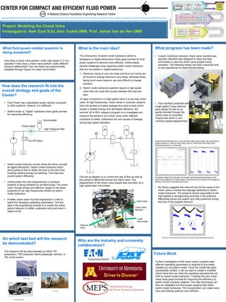
- 1. Who are the industry and university collaborators? How does the research fit into the overall strategy and goals of the Center? Project: Modeling the Check Valve Investigators: Alek Gust SJU, Alex Yudell UMN, Prof. James Van de Ven UMN What progress has been made? On which test bed will the research be demonstrated? What is the main idea?What fluid power-related question is being answered? Georgia Institute of Technology | Milwaukee School of Engineering | North Carolina A&T State University | Purdue University | University of Illinois, Urbana-Champaign | University of Minnesota | Vanderbilt University Future Work • Fluid Power has unparalleled power density compared to other systems, however it is inefficient. • Switch-mode or “Digital” hydraulics show great promise for improving efficiency. Accumulator Check Valve High Pressure Rail On-Off Valve • Switch-mode hydraulic circuits utilize the same concept as digital electronics. Switch-mode hydraulics direct short pulses of flow to either the load or the tank thus avoiding wasting energy by metering. This improves overall system efficiency. • Unfortunately this new advancement in hydraulic systems is being hindered by old technology. The check valve, though simple and effective, begins to fail when subjected to the high frequencies utilized by switch- mode hydraulics. • A better check valve must be engineered in order to reach the necessary operating parameters. The first step in the engineering process is to model the check valve’s behavior to better understand why and when it begins to fail. The introduction of switch-mode hydraulics (which is analogous to digital electronics) holds great promise for fluid power systems to become more efficient. Unfortunately, several challenges arise regarding switch-mode hydraulics that are not present in digital electronics: 1. Electrons, being of very low mass and thus low inertia can be forced to change directions very easily. Whereas fluids, being much more massive, are very difficult to change direction. 2. Switch mode hydraulics systems require a high speed valve that can route flow quickly between the load and tank. A major component in a high speed valve is a one way check valve. At high frequencies, check valves in hydraulic systems have the tendency to allow leakage flow back to tank which results in wasted energy and decreases efficiency. My summer 2014 REU research program is to investigate and measure the behavior of a check valve under different conditions to better understand the root causes of leakage during high speed operation. How does a check valve perform under high speed (< 5 ms) operation? How does a check valve perform under different pressure differentials? Can this theory be experimentally validated through means of a laser micrometer? This set up allowed us to control the rate of flow as well as the pressure differential across the check valve. The displacement of the check valve poppet was recorded via a high speed laser micrometer. This research will be demonstrated on either TB1 (excavator), TB3 (hydraulic hybrid passenger vehicle), or TBα (wind power). • Custom machined hydraulic check valve manifold was required. Manifold was designed to allow the laser micrometer to view the check valve poppet during operation. The following design has been machined and is now operational for experimental testing. • This manifold combined with a high speed 3-way solenoid valve allows for flow to be rapidly directed through the check valve at controlled frequencies which in turn controls poppet displacement. Using this experimental set up, the preliminary data shown below was acquired at a system pressure of 1500 psi and a duty cycle of .5 (50% tank 50% load) with a switching frequency of .5 seconds. The signal voltage from the laser micrometer and the actual displacement of the check valve poppet are of linear relation, thus both show a rebound of the poppet as the flow to the load is reverted back to tank. • My theory suggests this rebound can be the cause of the check valve’s reverse flow leakage attributed to switch- mode hydraulics. The pressure sensor associated to the load depicts a corresponding anomaly in the pressure differential across the system and load pressures during the time of the poppets rebound. *This data is not conclusive as this was only a single (though repeatable) experiment. Further investigation of the check valve’s poppet under different operating parameters is required to accurately validate our simulation model. Once the model has been successfully verified, it can be used to create a modified check valve that can meet the operating requirements set forth by switch-mode hydraulics. Creating this new check valve holds great promise for improving the efficiency of switch-mode hydraulic systems. This new technology can then be integrated into fluid power systems that utilize switch-mode hydraulics. This incorporation can make many new and existing systems more efficient.Excavator Passenger Vehicle Wind Power Laser Micrometer Check Valve Manifold Relief Valve Solenoid Valve