1. US 20080008597Al
(12) Patent Application Publication (10) Pub. No.: US 2008/0008597 A1
(19) United States
Dannemiller et al. (43) Pub. Date: Jan. 10, 2008
(54) WRIST MOUNTED PADDLE GRIP
Tristen Marie Dannemiller,
Carlsbad, CA (US); Michael
Anthony Totaro, Placerville, CA
(Us)
(76) Inventors:
Correspondence Address:
DONN K. HARMS
PATENT & TRADEMARK LAW CENTER
SUITE 100, 12702 VIA CORTINA
DEL MAR, CA 92014
(21) Appl. No.: 11/821,156
(22) Filed: Jun. 21, 2007
Related US. Application Data
(60) Provisional application No. 60/816,210, ?led on Jun.
23, 2006.
Publication Classi?cation
(51) Int. Cl.
B63H 16/04 (2006.01)
(52) US. Cl. ................................................... .. 416/70 R
(57) ABSTRACT
A Wrist engageable paddling device adapted for engagement
over the end of a paddle or oar. The device features a
member having a hooked portion extending from a Wrist
band. The hooked portion has a curve adapted for removable
engagement over the oar or paddle and is contoured for a
comfortable positioning between the palm of the user grip
ping the paddle. A ?exible engagement ofthe member to the
Wrist strap provides for rotation of the member to a stoWed
position With its distal end engaged over a side edge of the
strap. Neoprene or other compressible material provides for
a cushioning for the user’s arm and palm.
4. US 2008/0008597 A1
WRIST MOUNTED PADDLE GRIP
FIELD OF THE INVENTION
[0001] This application claims priority from US. Provi
sional Patent Application Ser. No. 60/816,210 ?led Jun. 23,
2006. The device herein described and enclosed relates
generally to paddles employed for paddling small Water
craft. More speci?cally, the disclosed device relates to a
Wrist mounted device employing a rotationally engaged
hook portion providing for a mechanical engagement
betWeen the user’s arm and the paddle While paddling the
Water craft.
BACKGROUND OF THE INVENTION
[0002] Kayaking and other roW sports are becoming
increasingly popular in the United States and abroad. There
are many different kinds of small, personal Water craft as
Well as various means to propel them manually such as With
oars or paddles.
[0003] Boats and paddles vary greatly and are designed
With the buyers intent in mind. Thus, there are calm Water
kayaks, White Water kayaks, sea kayaks, river canoes, calm
Water canoes and a myriad of others. Kayaks ?rst came into
existence in the Arctic North, a type of canoe built by
Eskimos by stretching animal hides over a frame. While
technologically improved, modern kayaks, are made from
anything from plastic to Kevlar to ?berglass. HoWever, they
share the same basic cockpit design as the original Eskimo
inspired Water craft Which maintains the user close to the
surface of the Water thereby yielding superb control.
[0004] The sport of kayaking is said to be groWing almost
faster than any other “extreme” sport, second only to snoW
boarding. Much of this groWth can be attributed to the
improved hull design of kayaks. These improved designs
provide increased performance Which alloW tricks such as
Wave sur?ng, spins and car‘tWheels easier to accomplish
thereby taking the sport in a neW direction. Additional
performance enhancement has been achieved Where Kayak
designers have taken cues from surfboard and Wakeboard
designs thereby creating kayak shapes that plane and lift the
kayak out ofthe Water. This enhancement in the riding level
of such kayaks provides for neW tricks by making them
easier to accomplish for both novice and experienced kay
akers.
[0005] The popularity of this neW brand of kayaking has
inspired promoters to start holding kayak rodeos across the
country. These competitions are held to shoWcase neW and
inventive tricks being performed in kayaks. Consequently,
the kayak, once a simple means of transportation, has
evolved into an outdoor toy of sorts With its usual transport
function being supplanted by the desire to push user per
formance limits as Well as adrenaline.
[0006] Contrary to the rapid development of the kayak
itself and other small personal Water craft, the paddle or oar
Which must be employed to manually propel them has been
virtually stagnant in development for some years. The
conventional kayak paddle consists of a shaft that is gener
ally 1.25 inches in diameter. On at least one end and more
often upon both ends of the shaft, blades are positioned
Which may be perpendicular to one another or parallel,
depending on user preference.
[0007] Rafting and canoe paddles are similar in structure;
hoWever, rafting paddles are generally slightly shorter than
Jan. 10, 2008
their kayak counterparts. Further, instead of being double
bladed, one end of the shaft is ?tted With a T-grip for
gripping and ease of use.
[0008] The shaft of conventional paddles is made of a
lightWeight non-corrosive material and is often sectional,
thereby providing an ability to disassemble the paddle for
storage or transport. As a general rule, no structure is
provided on the shaft itselfto ease the gripping ofthe paddle
by the user. This lack of structure for hand and paddle
engagement leaves the user to modify a neW paddle as they
see ?t. Common modi?cations include athletic tape for
increased friction and comfort as Well as thin rubber or
neoprene sleeves Which engage over the shaft to increase
grip potential by the user’s hands. Formed of compressible
?exible material, the sleeves also dampen vibration and
provide padding to the hand during a long day of paddling.
[0009] Due to the increased popularity of these small
Watercraft sports, long term Wear and tear injuries to the
hands and arms ofthe user, resulting from years ofpaddling,
have been magni?ed. RoWing, Whether in a canoe With a one
bladed paddle or in a kayak With a double bladed paddle, is
an exhausting and repetitive motion favoring the overuse of
the Wrist, elboW and hands. Overuse of these parts of the
body most commonly result in Carpal Tunnel Syndrome
(hands), Arthritis (hands, elboW, Wrist) and Tendinitis (el
boW, Wrist). Further injury may occur as a result of simple
hand fatigue from grasping a paddle for multiple hours.
Furthermore, ifan accident Were to happen in the open Water
leaving a user’s hands unusable, they Would be unable to
paddle to shore to seek the attention they need.
[0010] Thus, there is an unmet need for a device that
alloWs the user an enhanced means of engagement to the
paddle. Such a device should reduce the hand strength
required to grip the paddle Without rendering the paddle less
effective during use. Furthermore, there is a need to provide
such a device Which may engage the paddle to the arm ofthe
user While the user’s hands are completely free from grip
ping the paddle thereby enabling paddling Without direct
hand contact With the paddle. Still further, such a device
should alloW the user to reduce their gripping force on the
paddle and even disengage their hand While paddling, to
thereby reduce hand fatigue and injury. Additionally, such a
device should provide an easy release of engagement of the
user from the paddle should other use of the hands become
necessary. Additionally, such a device should provide for
both easy stoWing and offer a comfortable non-chaf?ng
engagement to the Wrist of the user. Further, such a device
should provide for an enhanced engagement ofthe paddle to
the arm, yet concurrently provide some shock absorption to
reduce fatigue and injuries. Lastly, and ofparticular concern,
such a device should ?oat in the event it became detached
from the user and should be constructed of easily spotted
material so as to prevent it from becoming lost in the Water.
SUMMARY OF THE INVENTION
[0011] There is disclosed and described herein a device
that When in the preferred mode alloWs the user to employ
substantially less grip force upon the paddle When employ
ing a paddle to manually propel a small personal Water craft
such as a kayak or canoe. The disclosed device also alloWs
the user to completely disengage their hands from the paddle
and impart force to the paddle to continue propulsion. The
device is removably engaged to the user at the Wrist and is
5. US 2008/0008597 A1
made of a comfortable non-cha?ng material Which Will ?oat
and can be easily seen if it becomes disengaged from the
user.
[0012] IN a preferred mode, the device consists of a strap
adapted for encircling the Wrist. Attached to the underside or
palm side of the Wrist strap by a ?exible means of engage
ment is a planar hook extending out from the palm. This
hook, When engaged to the paddle, surrounds the shaft ofthe
paddle While the hand concurrently grips the paddle over the
hook. The strap-engaged hook in this engagement With the
paddle transfers much ofthe force from paddling to the arms
and shoulders and thereby aWay from the hands and Wrists
Which alloWs for a looser grip. Should the user ?nds it
necessary to disengage the hook portion of the device from
the paddle, the ?exible connection alloWs the user to easily
disengage the hook and rotate it 180 degrees along the axis
ofthe arm to an engagement of the hook portion to the Wrist
strap, thereby proving a secure location When not engaged to
the paddle.
[0013] The hook portion ofthe device is best formed from
a strong and durable but also slightly ?exible material.
Plastics such as polypropylene or nylon, composites like
?berglass or carbon ?ber, or lightWeight metals such as
aluminum Work Well to provide the substantially rigid yet
?exible portion of the hook. The hook portion in the
preferred mode is surrounded by a polypropylene or like
material Webbing cover Which is stitched to form the cover.
This Webbing or other fabric type cover mitigates Wear to the
paddle, adds buoyancy to the device, and provides comfort
to the hand While engaged over the hook When gripping the
paddle. An upper surface of the hook Which is in contact
With the palm When the user’s hand is engaged to the paddle,
in a particularly preferred mode of the device, is ?tted With
a strip of neoprene or similar cushioning material to add
further buoyancy to the device and comfort to the hand When
engaging the paddle over the hook.
[0014] The base of the hook, opposite its hooked distal
end, is connected to the Wrist strap portion by a ?exible
means of engagement thereby alloWing rotation of the hook
along the axis of the arm. This rotation alloWs the hook to
move With the hand during roWing or paddling and alloWs
the user to disengage the hook portion from the paddle and
rotate it toWard the elboW to an engagement ofthe distal end
of the hook With the Wrist strap. This engagement provides
for a means to secure the hook portion out of the Way of the
user When not in use. Means for ?exible or rotational
engagement is achieved using a fabric hinge to attach the
base portion ofthe hook to the Wrist strap. By appropriately
curving the distal end of the hook, the ?exibly connected
hook can thereby be rotated along the axis of the arm to
frictionally engage the distal end of the hook to the Wrist
strap, securing the hook out of the Way of the user and
rendering it unable to interfere When not in use.
[0015] The Wrist strap portion of the device formed of
fabric such as a polypropylene or like material Webbing
provides further buoyancy. The inside of the Wrist strap,
Which is adapted for encirclement and contact With the Wrist,
is lined With a compressible material such as neoprene,
providing additional buoyancy as Well as increased comfort
and shock absorption. Engagement of the tWo ends of the
Wrist strap is provided by a fastener Which in the current
preferred mode is by a hook and loop style fabric. Such an
engagement provides a soft fastener and adjustable overlap
of the tWo ends of the strap thereby alloWing one siZe strap
Jan. 10, 2008
to ?t all users. Additionally provided, in a preferred mode of
the device, small mounts on the top of the Wrist strap alloW
the user a means to engage a Wrist Watch or compass to the
exterior surface of the Wriststrap for easy vieWing.
[0016] Also provided on the device is a means of ?oata
tion should it become detached from the Wrist of the user
Which concurrently provides a means for visual enhance
ment to thereby easily visually spot the device from a
distance or in loW light. Due to the liberal use of materials
like neoprene and polypropylene, Webbing in the construc
tion of the device buoyancy is easily achieved by simple
material choice. By using neoprene and polypropylene Web
bing, bright color options are available alloWing the device
to be easily spotted from a distance or in poor lighting
conditions.
[0017] In this respect, before explaining at least one
embodiment of the invention in detail it is to be understood
that the invention is not limited in its application to the
details of the construction and to the arrangement of the
components set forth in the folloWing description of illus
trated in the draWings. The invention is capable of other
embodiments and of being practiced and carried out in
various Ways. Also, it is to be understood that the phrase
ology and terminology employed herein are for the purpose
of description and should not be regarded as limiting.
[0018] As such, those skilled in the art Will appreciate that
the conception upon Which this disclosure is based may
readily be utiliZed as a basis for designing of other methods
and systems for carrying out the several purposes of the
present invention. It is important, therefore, that the claims
be regarded as including such equivalent construction inso
far as they do not depart from the spirit and scope of the
present invention.
[0019] It is an object of this invention to provide the user
a means of engagement to a paddle Which alloWs a looser
hand grip to impart force to a paddle employed to manually
propel a small personal Water craft.
[0020] It is an object of this invention to provide the user
a means of engagement to a paddle to the arm, during
periods Where the paddle is not gripped by the hands,
thereby alloWing the user to stroke the paddle Without hand
engagement to the paddle.
[0021] It is further an object of this invention to provide a
means to retract the device out of the user’s Way While still
being Worn.
[0022] Lastly, it is an object of this invention to provide a
device that Will ?oat should it become detached from the
user, made from bright colors that are easily seen from a
distance or in poor lighting conditions and of a comfortable
non-chaf?ng material.
[0023] These, together With other objects and advantages,
Which Will become subsequently apparent, reside in the
details of the construction and method as more fully here
inafter described and claimed, reference being had to the
accompanying draWings forming a part thereof, Wherein like
numerals refer to like parts throughout.
BRIEF DESCRIPTION OF THE DRAWING
FIGURES
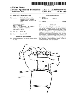
[0024] FIG. 1 depicts the disclosed device in the as-Wom
position on the Wrist of a user With the distal end ofthe hook
portion removably engaging a paddle.
[0025] FIG. 2 depicts an opposite vieW of FIG. 1 shoWing
the distal end of the hook portion curved to the contour of
6. US 2008/0008597 Al
the palm of a hand and to encircle a paddle or oar With the
hand in a naturally curved position.
[0026] FIG. 3 shows the device in an unmounted con?gu
ration showing the Wrist strap, padding, and fabric hinge
engaging the ?rst end of the hook portion. Also shoWn are
the means for engagement for a Wrist Watch.
[0027] FIG. 4 is a side vieW of the device.
[0028] FIG. 5 depicts the initial rotation of the hook
portion on the fabric hinge toWard the loWer or opposite
edge of the Wrist strap.
[0029] FIG. 6 shoWs the device With the hook portion
rotated to a retracted position With the distal end of the hook
portion engaged over the loWer edge of the Wrist strap.
DETAILED DESCRIPTION OF THE
PREFERRED EMBODIMENTS
[0030] Referring noW to the draWings in FIGS. 1-6, the
preferred embodiments of the present invention in current
preferred modes are shoWn and described. As shoWn, FIG.
1 depicts the disclosed device 10 in an as-Wom position on
the Wrist of a user. A hook portion 12 is curved to a
termination at a distal end 14 and the curve has an arc
adapted to removably encircle a shaft of a paddle 16 or an
oar.
[0031] A removably engageable Wrist strap 18 is
employed to engage the device 10 to the user’s Wrist. The
Wrist strap 18 is elongated and has fastening means such as
hook and loop fabric fasteners 20 at opposite distal ends to
alloW for adjustable encirclement by the strap to engage
many siZe Wrists.
[0032] FIG. 2 depicts the reverse vieW of FIG. 1 With the
hook portion 12 extending from the Wrist band 18 and
having a curve terminating at a distal end 14 and engaged
around a paddle 16. The distal end 14 is curved to conform
to the contour of the user’s hand and to encircle a paddle 14
With the hand concurrently in a relaxed and naturally curved
position.
[0033] In FIG. 3 is shoWn the Wrist band 18 in an
unmounted con?guration. At one distal end is located hook
fabric 22 that is easily and adjustably engageable to the loop
fabric 24 fastening material on the opposite end. The hook
fabric 22 and loop fabric 24 thereby provide means for
removable engagement of the distal ends of the Wrist strap
to each other. The elongated siZe ofthe hook and loop fabric
also provides means for adjustment of the siZe of the Wrist
band 18 by alloWing for engagement of the distal ends in an
adjustable overlap. Also shoWn is the fabric hinge 15 pro
viding means for ?exible and rotational engagement of the
hook portion 12 to the Wrist band 18. So engaged, the hook
portion 12, sandWiched betWeen the hand and palm of a user
and the oar or paddle, Will move in concert With the hand
rotating on the Wrist of the user during a stroke. Stitching 25
is employed throughout the device 10 to hold the compo
nents together, although those skilled in the art Will realiZe
other means to hold the components operatively engaged
may be employed and such is anticipated Within the scope of
this patent.
[0034] The hook portion 12 is formed ofa spine 13 portion
that is encased in a sheath 17. The spine 13 is employed in
the hook portion 12 to impart ?exible rigidity to the hook
portion 12. The spine 13 is made from substantially rigid
material that provides some ?ex during use such as rigid
plastic, carbon ?ber, or ?berglass, or substantially rigid yet
?exible metal such as aluminum. It is important to provide
Jan. 10, 2008
this ?ex as a means for shock absorption and as a means to
store energy Which is imparted With a slight springing action
at the end of a stroke. Covering the spine 13 is the sheath 17
Which is best formed of rugged fabric such as seat belt
Webbing to resist cha?ing and provide a pad to the hand of
the user from the spine 13. The con?guration of the spine 13
engaged Within the sheath 17 Which is engaged to the Wrist
band 18 When in the as-Worn position of FIG. 2 in combi
nation provides means to transfer force from the paddle to a
position on the arm rearWard of the hand and palm during
the pull portion of the stroke of the paddle 16. This transfer
of force from the hand and Wrist thereby aids in preventing
injuries to tendons of the hand such as Carpel Tunnel
Syndrome and other repetitive stress injuries Which occur
from conventionally gripping and pulling of the paddle.
[0035] As noted, a particularly preferred component ofthe
device 10 is a means to retract the hook portion 12 to a
removably secure retracted position as shoWn in FIG. 6. This
unique utility function is provided by the combination ofthe
fabric hinge 15 engaging the ?rst end of the sheath 17
encased spine 13 of the hook portion 12 thereby alloWing a
rotation ofthe hook portion 12. Rotation ofthe hook portion
12 alloWs the distal end of the hook portion to engage over
a loWer edge 27 ofthe Wrist strap 18. The user can thus rotate
the hook portion 12 to the secured and retracted position of
FIG. 6 easily and reverse back to the deployed position of
FIGS. 1-2.
[0036] ShoWn best in FIG. 3 is also the neoprene lining 29
Which is siZed slightly Wider than the Wrist strap 18. The
lining 29 provides a padding to the forearm of the user to
resist cha?ing to the arm from the leading and rear edges of
the Wrist strap. ColoriZing the lining 29 to a bright or
?uorescent color provides means easily visually spot the
device 10 in its surroundings should it become disengaged
from the Wrist.
[0037] Finally, an especially preferred mode ofthe device
includes a means for engagement to a WristWatch or com
pass Which in the current preferred mode is provided by
mounts 33 on the exterior surface of the Wrist strap 18.
Experimentation has shoWn that many users Would cover
their Watch With the Wrist strap 18 and providing means to
engage a Watch is especially helpful. These mounts 33, may
be hook and loop fabric adapted in siZe to engage a hook and
loop Watch band of an existing Watch or loops adapted to
engage the crossbars of Watch bodies. The mounts 33 also
provide means to engage a compass to the device 10 Which
is especially helpful When traversing back country areas.
[0038] The Wrist mounted paddle gripping device shoWn
in the draWings and described in detail herein, discloses
arrangements of elements of particular construction and
con?guration for illustrating preferred embodiments of
structure and method of operation of the present invention.
It is to be understood, hoWever, that elements of different
construction and con?guration and other arrangements
thereof, other than those illustrated and described, may be
employed for providing a device Within the spirit of this
invention.
[0039] As such, While the present invention has been
described herein With reference to particular embodiments
thereof, a latitude of modi?cations, various changes and
substitutions are intended in the foregoing disclosure, and it
Will be appreciated that in some instance some features of
the invention could be employed Without a corresponding
use of other features Without departing from the scope ofthe
7. US 2008/0008597 A1
invention as set forth in the following claims. All such
changes, alternations and modi?cations as Would occur to
those skilled in the art are considered to be Within the scope
of this invention as broadly de?ned in the appended claims.
What is claimed is:
1. A paddle engagement apparatus adapted for engage
ment to the arm of a user, comprising:
a strap, said strap formed of ?exible material, said strap
having a length extending along tWo side edges
betWeen a ?rst end and a second end, said strap having
a Width;
means for removable engagement of said ?rst end to said
second end Whereby said strap is engageable around the
arm of a user adjacent to the Wrist, in an as-Worn
position;
a hook member, said hook member having a ?rst end and
having a distal end opposite said ?rst end;
said hook member having a curved portion adjacent to
said distal end, said curved portion forming a hooked
portion of said hook member;
said curved portion shaped to engage upon an exterior
surface of an oar or paddle While in a sandWiched
position betWeen a palm of the hand of a user and said
exterior surface; and
means for ?exible engagement of said ?rst end of said
hook member to said strap Whereby said hook member
in said sandWiched position is moveable in concert With
said hand of said user.
2. The paddle engagement apparatus of claim 1 addition
ally comprising:
said hook member rotatable upon said means for ?exible
engagement from a ?rst position extending from a ?rst
of said side edges to a second position; and
said distal end of said member rotatable to stoWed posi
tion With said hooked portion in a removable engage
ment upon a second of said side edges, opposite said
?rst of said side edges.
3. The paddle engagement apparatus of claim 1 addition
ally comprising:
said hook member being planar and having a spine
component surrounded by a cover;
said spine component formed of a rigid yet slightly
?exible material;
said cover formed of a ?exible fabric material; and
means for engagement of said cover to said means for
?exible engagement.
4. The paddle engagement apparatus of claim 2 addition
ally comprising:
said hook being planar and having a spine component
surrounded by a cover;
said spine component formed of a rigid yet slightly
?exible material;
said cover formed of a ?exible fabric material; and
means for engagement of said cover to said means for
?exible engagement.
5. The paddle engagement apparatus of claim 1 addition
ally comprising:
a cushioning layer, said cushioning layer engaged to an
interior surface of said strap in a position to be sand
Wiched betWeen the Wrist of said user and said strap
When in the as-Wom position; and
said cushioning layer having a Width Wider than said
Width of said strap.
Jan. 10, 2008
6. The paddle engagement apparatus of claim 2 addition
ally comprising:
a cushioning layer, said cushioning layer engaged to an
interior surface of said strap in a position to be sand
Wiched betWeen the Wrist of said user and said strap
When in the as-Worn position; and
said cushioning layer having a Width Wider than said
Width of said strap.
7. The paddle engagement apparatus of claim 3 addition
ally comprising:
a cushioning layer, said cushioning layer engaged to an
interior surface of said strap in a position to be sand
Wiched betWeen the Wrist of said user and said strap
When in the as-Worn position; and
said cushioning layer having a Width Wider than said
Width of said strap.
8. The paddle engagement apparatus of claim 4 addition
ally comprising:
a cushioning layer, said cushioning layer engaged to an
interior surface of said strap in a position to be sand
Wiched betWeen the Wrist of said user and said strap
When in the as-Worn position; and
said cushioning layer having a Width Wider than said
Width of said strap.
9. The paddle engagement apparatus of claim 1 Wherein
said means for removable engagement of said ?rst end is a
fastener, said fastener proving an overlapping engagement
of said ?rst end to said second end in a plurality ofpositions;
and
said overlapping engagement providing means to adjust
said strap to accommodate varying siZes of said arm of
said user.
10. The paddle engagement apparatus of claim 2 Wherein
said means for removable engagement of said ?rst end is a
fastener, said fastener proving an overlapping engagement
of said ?rst end to said second end in a plurality ofpositions;
and
said overlapping engagement providing means to adjust
said strap to accommodate varying siZes of said arm of
said user.
11. The paddle engagement apparatus of claim 3 Wherein
said means for removable engagement of said ?rst end is a
fastener, said fastener proving an overlapping engagement
of said ?rst end to said second end in a plurality ofpositions;
and
said overlapping engagement providing means to adjust
said strap to accommodate varying siZes of said arm of
said user.
12. The paddle engagement apparatus of claim 4 Wherein
said means for removable engagement of said ?rst end is a
fastener, said fastener proving an overlapping engagement
of said ?rst end to said second end in a plurality ofpositions;
and
said overlapping engagement providing means to adjust
said strap to accommodate varying siZes of said arm of
said user.
13. The paddle engagement apparatus of claim 8 Wherein
said means for removable engagement of said ?rst end is a
fastener, said fastener proving an overlapping engagement
of said ?rst end to said second end in a plurality ofpositions;
and
said overlapping engagement providing means to adjust
said strap to accommodate varying siZes of said arm of
said user.
8. US 2008/0008597 A1
14. The paddle engagement apparatus of claim 9 Wherein
said fastener is hook and loop fabric.
15. The paddle engagement apparatus ofclaim 10 Wherein
said fastener is hook and loop fabric.
16. The paddle engagement apparatus of claim 11 Wherein
said fastener is hook and loop fabric.
17. The paddle engagement apparatus ofclaim 12 Wherein
said fastener is hook and loop fabric.
18. The paddle engagement apparatus of claim 16 addi
tionally comprising:
means to engage a Watch to an exterior surface of said
strap to a position VieWable by said user When said strap
is in said as-Wom position.
Jan. 10, 2008
19. The paddle engagement apparatus of claim 17 addi
tionally comprising:
means to engage a Watch to an exterior surface of said
strap to a position VieWable by said user When said strap
is in said as-Wom position.
20. The paddle engagement apparatus of claim 2 addi
tionally comprising:
means to engage a Watch to an exterior surface of said
strap to a position VieWable by said user When said strap
is in said as-Wom position.