1. An Examination of the Lost Pencheck Staircase of Old Penicuik House
Report Submitted for the Culture and Performance in the History of Construction –
(ARCH1117))
Dip/MSc in Architectural Conservation
University of Edinburgh
Adam Thomson
s1162034
EDINBURGH SCHOOL OF ARCHITECTURAL AND LANDSCAPE
EDINBURGH COLLEGE OF ART
UNIVERSITY OF EDINBURGH
2012/2013
2. 2
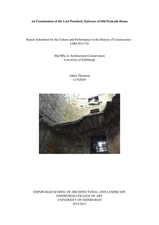
FIG. 1, Pencheck staircase at Penicuik House –
Image from “Country Life” magazine, August 15, 1968.
3. 3
Contents:
Acknowledgements 4
1. Introduction to Study Area and Construction History 5
2. Survey Methodology and Key Measurements 6
3. Research and Analysis of Geometry and Process of Assembly 6
4. Model Making Stages 9
5. Analysis of Original Construction Techniques, Performance,
Site Organisation and Relation to Rest of Building 11
6. Results of model performance testing 12
7. Conclusion 15
8. Bibliography 16
4. 4
Acknowledgements
Simpson & Brown Architects;
Graeme Brown Stonemason Ltd;
Stuart Beattie, Project Manager, Penicuik House Project; and,
Training and Education Officer, Scottish Lime Centre Trust.
5. 5
1 Introduction to Study Area and its Construction History
The historic construction process selected to model is the missing eastern stone penchecked
(or hanging) staircase of the Category A listed ruin of the Palladian mansion of Penicuik
House, located in the countryside on the eastern edge of the Pentland Hill (see Figs. 1 & 2).
The building; which was gutted by fire in 1899 and is roofless is a long oblong internally
symmetrical building consisting of a piano nobile with attic and basement (see Fix. 3). It was
built in 1761-69 by Sir James Clerk, with the assistance of John Baxter.
When a young man James Clerk had gone to Rome as an amateur of architecture.1
Perhaps
it is here he gained the visual knowledge of the construction of penchecked staircases and an
understanding of how they work.
Fig. 2. Plan of First floor of Penicuik House, courtesy of Simpson & Brown Architects
Fig. 3. Photograph of Penicuik House on the day of the fire in 1899.
6. 6
2 Survey Methodology and Key Measurements
In preparing to model the staircase a plan of scale 1:10 of the staircase was drawn using the
floor plans and section drawings of the ruins of the building at scale 1:100 prepared by
Simpson and Brown Architects. Although these drawings delineate only the few remaining
steps of the staircase, given that the staircase was symmetrical, from the few steps that remain
and which are delineated on the plans and from an on-site analysis it was possible to prepare
a complete plan of the staircase with the position of all of the steps delineated. Owing to time
constraints it was not possible to undertake a measured on-site survey of the staircase.
However, photographs were taken of the ruins of the staircase which assisted in completing
the scale plan of it. Using a photocopier, the hand drawn plan of scale 1:100 of the eastern
staircase was rescaled to 1:10. The plan was mounted onto a board to form a template for the
staircase and steps. Where it was not possible to inspect details of the staircase owing to
access difficulties, a pencheck staircase within the Victorian tenement (circa 1890) at 19/3
East Preston Street, Edinburgh, was used as a benchmark.
3 Research and Analysis of Geometry and Process of Assembly
Pencheck staircases get there name from the recess or `pencheck’ groove formed at the
bottom of the riser of the step which interlocks with the top of the back of the step below
(Fig. 3). The recess is cut square or angular so that the steps lock together. The pencheck
prevents the steps from twisting. If the pencheck was rounded the steps would be more
susceptible to twisting.
Fig. 3. Close-up of angled penchecks of steps of
the staircase at 19 East Preston Street, Edinburgh.
7. 7
Stone penchecked staircases are not uncommon. They are found around the world in several
historic buildings built over the last 400 years.1
They are typical in Scottish tenements.
Hume informs that they exist in many countries and that although it is clear that the builders
understood how they worked this knowledge is not now widely held.2
They have no visible means of support. Taylor asks “how could a brittle piece of stone
project 1,200 or 1,500mm out from a wall without snapping in two?”3
The answer is that the
steps are not cantilevers. If they were the steps would be anchored at one end into the
stairwell wall which wall would be the only support. There would be no support under the
outer edge of the individual steps. Nevertheless penchecked stairs are a misnomer and
commonly referred to as cantilever stairs.
How they work is that each tread transfers weight to the back of the tread below and that
tread then transfers load onto the back of the next tread and so on.4
This relies on torsional
resistance at the point where the step is built into the wall to stop the step from twisting. Part
of the load is carried by the stairwell walls and part is transferred through the treads to the
landing below.5
However, it must be the case that the load is carried back to the wall within a few treads. If
this were not the case the load at the landing at the bottom of the stairs would be too great for
the landing to carry. There are thus both horizontal and vertical thrusts. There are parts of
the staircase of Penicuik House where a few steps remain suspended. The load is sustained
because the stub of the step below remains in the wall and the stub is enough to provide a
degree of the proper action.
The pencheck allows the treads to act together so that a weakness in one does not bring about
the failure of the whole flight. It also allows the staircase to deal better with any movement
that might occur in the supporting stairwell wall.
1
Hume, Ian. Cantilever, Hanging or Pencheck Stairs, Journal of Architectural Conservation
July 2009. pp.79-90.
2
ibid.
3
Taylor, Russell. Stone Cantilevered Stairs, The Building Conservation Directory 2006.
4
Hume, Ian. Cantilever, Hanging or Pencheck Stairs, Journal of Architectural Conservation
July 2009. pp.79-90.
5
Davey, Heath, Hodges, Ketchin, Milne. The Care and Conservation of Georgian Houses.
(Fourth Edition) p.187.
8. 8
Fig. 4. Drawing the pencheck steps of Penicuik House with their curved soffits.
The staircase of Penicuik House comprised a series of flyers (straight steps) and winders
(steps with converging on tread). The underside of the pencheck stairs historically were
shaped in different ways. Some are left square, others are cut and some are rounded like
those at Penicuik House (see Fig. 5).
Fig. 5. Drawing of a pencheck step of
Penicuik House with their curved soffits.
9. 9
The quarter landings are constructed of three individual rectangular blocks of stone with ends
bedded into the staircase walls. The first block locks into the step below it with a pencheck.
The two end blocks have mitred ends and the middle block with its reversed mitred ends
locks into place between them. The load of the middle block is carried by both end blocks
(see Fig. 6).
Fig. 6. Illustration showing section of staircase and quarter landing with mitred ends.
The existing staircase walls of Penicuik house are constructed of rubble sandstone. A report
on a survey carried out by the British Geological Survey of a sample analysis and discussion
of the source of external and internal stone of Penicuik House states that the ashlar internal
stairs appears to be a `Craigleith type’ sandstone which was obtained from one or more
quarries in Edinburgh.
4 Model Making Stages
A model of a scale 1: 10 comprising three of the stair walls and part of the first floor flight of
stairs were constructed. The chosen material for the model of the steps is plaster of paris.
This was chosen because; being heavier than timber, it better replicates the weight of stone.
In actuality to construct stairs to full size the stonemason would have drawn a scaled plan on
a large board or platform. The same method was used for making the model of the stairs.
A timber model of both a flyer and a winder step was made using a combination of timber
sections glued together and air drying moulding clay. The riser (vertical) lines are essential to
the setting out both on plan and section. The finished timber models were then used to make
moulds with alginate impressions compound (see Fig. 7).
10. 10
Fig. 7. Photo of underside of plaster casts of flyer and winder
steps showing the penchecks and nosings.
In the case of the construction of the model, initially the plaster casts of the steps were affixed
to the plywood `walls’ of the model using cylindrical metal dowels embedded into the casts.
However, when the steps were put in place it was discovered that these cylindrical dowels
were not effective is preventing the steps from twisting (see Fig. 8). Therefore, the steps had
to be recast with a rectangular rebate which could be inserted into a corresponding
rectangular aperture cut into the plywood walls (see Fig. 9). This was more effective at
prevented the steps from twisting.
Fig. 8. Rejected first Casts with metal Fig. 9. Timber mould of winder step with timber
dowels inserted into the ends rectangular rebate glued over metal thread
Once the first casts of the steps were assembled into the staircase it was apparent that they did
not lock together to form a single stable staircase (see Fig. 10). The `treads’ did not sit level
11. 11
and pressure had to be applied to the top `step’ in order to get the run of steps to lock together,
albeit when pressure was applied the structure was strong. It became apparent that a
combination of inaccurately made moulds of the steps, poor casting and inaccurately
positioned and cut apertures cut within the stairwell `walls’ had prevented a good model of a
staircase from being formed (see Fig. 11). The unavoidable conclusion is that precision is
required when building a pencheck staircase and the same precision is required in making a
successful model of the staircase which functions as a real life pencheck staircase. The
decision was made to rebuild the model with precision (see Fig. 12).
Fig. 10. Failed attempt at assembly of first casts Fix. 11. First attempt at creating moulds of steps
Fig. 12. More precise second moulds.
5 Analysis of Original Construction Techniques, Performance, Site Organisation
and Relation to Rest of Building
The part of the step embedded into the wall is left as a square stone rebate for good reason. It
plays an important part in preventing the steps from twisting. It was confirmed on site that
each of the steps at Penicuik House were embedded into the stairwell wall by only
approximately 100mm. The stone rebates do not have the same profile as the steps; but
instead, the stonemason left the ends as cuboids. Given that the staircase walls are
constructed of rectangular sandstone blocks the cuboid ends would have been able to be
inserted into corresponding apertures in the wall and mortared in place with relative ease.
The stonemason will have made adjustments to the rebates and aperture in order for the
pencheck to sit correctly on the back edge of the step below. The gaps between the rebates
12. 12
and the apertures of the walls were bridged using stone pinning cut to shape and the thin
joints were lime mortared (see Figs. 13 & 14). If the ends of the steps had been the same
profile as the steps it would have been a much more difficult task for the stonemason to cut
the apertures in the staircase walls as this will have involved cutting several wall stones.
Fig. 13. Stone pinning of the remains of the Fig 14. Close-up of stone pinnings
staircase of Penicuik House circled in blue.
In the 18th
and 19th
centuries it is likely that a timber scaffold would have been erected within
the stairwell to assist in the construction of the stairs. This would be for ease of access for
construction and not necessarily for structural support because as each step was laid on top of
the one below the weight of the upper most step would be supported by the run of steps
below.
6 Results of Model Performance Testing
When assembling the casts of the steps both the rebates and aperture required some minor
cutting and sanding so that each step locked correctly into the pencheck of the step below.
Wide gaps were bridged using modelling clay (see Fig. 15). The aim was to get the step to sit
neatly into the pencheck of the step below and not to wedge the step into the aperture so that
it became cantilevered.
Fig. 15. Wide gaps owing to inaccurate cutting
of rebates were bridged with modelling clay.
13. 13
As anticipated, several steps were required to be inserted into place before the action of
weight on the upper step bearing down on the steps below resulted in a stable structure (see
Figs 16, 17 & 18).
Fig. 16. Assembled model of staircase.
Fig. 17. Assembled model of staircase Fig. 18. Assembled model of staircase
According to the stonemason at Penicuik House, when the staircase was constructed it is
probable that a layer of hydraulic lime would have been used between the steps. To test
whether a bonding would improve the stability of the model a thin layer of modelling clay
was placed at the point of contact of each of the steps. However, this did not achieve any
discernible improvement to the stability of the steps and in fact; the thickness of the
modelling clay unlevelled the steps. The conclusion is that it a bond is not necessary for the
structural support of the staircase.
When a step in the middle of the structure was taken out this distorted and weakened the
structure (See Fig 19). To replicate loss of rigidity in the wall, the bolts holding the plywood
`walls’ were adjusted on the threaded rods to bring the `walls’ off-square. This also resulted
in weakening of the structure.
14. 14
Fig. 19. Whole structure is weakened when a middle
Step is removed.
Weights were incrementally added to the treads of the steps of the model to test the strength
of the staircase. Up to a weight of 12kgs the staircase remained intact with no discernible
movement (see Fig. 20). At 12kgs one of the steps began to rotate (see Figs. 21 & 22). The
structure collapsed when a weight of 14.68kg was added (see Fig. 23). The rotating of and
then the eventual fracturing of the ends of the rebates of four of the upper steps led to the
collapse of the upper part of the model (see 24). This proves that the wall is carrying much of
the load. In actuality, full size working pencheck stairs would not at any one time have to
carry a load equivalent to that placed on the model and which resulted in its collapse.
Fig. 20. Weights amounting to 7.37kgs were
placed onto the treads of the casts of the steps.
15. 15
Fix. 21 & 22. Rotation in one of the steps with weigh of 12kgs added.
Fig.23. Failure of structure with weight of Fig.24. structural failure resulting from
14.68kg added. fracturing of rebated ends within the `wall’
7 Conclusion
When the steps and stairwell walls of a pencheck staircase are in good condition and the
structure is intact the staircase is immensely strong. Everything in the structure has to be
rigid and the steps tightly bedded with every step interlocked otherwise the torsional forces
will not be restrained.
In creating a working model of a staircase requires precision in setting out and construction,
including accurately calculating the dimensions of the steps in order to create sound casts of
the steps which when assembled will connect to form a strong stable structure. In particular,
accuracy is required in the rebated ends of the steps and the corresponding apertures in the
stairwell wall to prevent rotating of the steps. The same precision is required when
constructing a pencheck staircase in real life. Such precision would be challenging to a
stonemason in the 18th
and 19th
centuries who would only have the use of hand tools.
However, today we have computers and lasers to accurately calculate dimensions to assist the
stonemason, thus making the process simpler.
16. 16
8 Bibliography
British Geological Survey. Report on an analysis of the source of external and internal
stone of Penicuik House.
Country Life, August 15, 1968.
Davey, Heath, Hodges, Ketchin, Milne. The Care & Conservation of Georgian Houses.
Third Edition, p.187-190).
Hume, Ian. Cantilever, Hanging or Pencheck Stairs, Journal of Architectural
Conservation July 2009. pp.79-90.
Purchase W. R., “Practical Masonry A Guide to the Art of Stone Cutting” Sixth Edition,
Crosby Lockwood and Son, Stationers’ Hall Court, Ludgate Hill, 1928. pp.27-45.
Taylor, Russell. Stone Cantilevered Stairs, The Building Conservation Directory 2006,
available at https://www.buildingconservation .com/articles/stonecantstairs.htm.