
Recommended
More Related Content
What's hot
What's hot (20)
Similar to AC Generator Project Report Breakdown
Similar to AC Generator Project Report Breakdown (20)
Recently uploaded
Recently uploaded (20)
AC Generator Project Report Breakdown
- 1. 1 Submitted to Submitted By Mr.Vipin Mishra Anushika Kapoor, XII-A Board Roll No____________ 2022-23 Topic:- AC Generator PHYSICS PROJECT REPORT DELHI PUBLIC SCHOOL, REWARI
- 2. 2 Contents ❖Certificate ❖Acknowledgement ❖Introduction ❖Principal of AC Generator ❖Construction of AC Generator ❖Theory ❖Circuit Diagram ❖Working of AC Generator ❖Expression of Instantaneous e.m.f produced ❖Applications of AC Generator ❖Advantage of AC generator over DC Generator ❖Bibliography
- 3. 3 Certi fi cate This is to certify that Anushika Kapoor, a student of class 12thA has successfully completed the project of AC-Generator under the guidance of Mr.Vipin Mishra (Physics Teacher) During the academic year 2022~23 in partial ful fi lment of physics practical Examination conducted by CBSE. Signatures of Teacher
- 4. 4 ACKNOWLEDGEMENT A good project involves the hard work of many people, including the students and the teacher. While working on this project, I have received unconditional support and guidance from many people. I want to thank all of them. Among all of them, I have received tireless collaboration from my teacher, Mr.Vipin Mishra I would like to express my sincere gratitude to my teacher, Mr.Vipin Mishra, for giving me such a golden opportunity to work on this wonderful project on AC Generator. Mr.Vipin is my mentor, who has helped me throughout this project by providing important data and information. His valuable words and advice have truly motivated me. Preparing this project in collaboration with my teacher was a refreshing experience. I have learned many useful things from this project. His guidance and constant support have pushed me to successfully complete this project. I convey my heartfelt regards and appreciation for his sincere co-operation in this project. I also want to thank my principal, Ms Sunita Chopra, who have directly and indirectly helped me accomplish this project. Yours faithfully, Anushika Kapoor
- 5. 5 INTRODUCTION An AC generator also called the Alternating Current Generator is a type of device that converts the mechanical energy that is present into alternating energy for daily use in various appliances. AC generators contain slip rings to produce alternating currents whereas DC generators tend to use direct current as the result of the DC generator. Bicycles, electric scooters, microwaves, and sailboats all use the AC generator to produce AC current. Mechanical energy is provided by steam and gas turbines as well as internal combustion engines to the AC generators. These are also highly useful in wind turbines and small hydropower plants in order to convert the high-pressure gas streams to lower pressure zones The machine which converts the mechanical energy into electrical energy in the output of alternating current or voltage is known as AC Generator. The machine works on Faraday's law of Electromagnetic induction. Here, the Direct Current voltage is made to rotate inside the fixed coil, like a huge power generator that produces the AC current. By using Fleming's right-hand rule, the direction of the alternating current in the generator is determined.
- 6. 6 Principal of AC-GENERATOR A.C. Generator is a device which is used to convert the mechanical energy in to electrical energy is called electric generator. Principle of A.C. Generator It is based on the principle of electromagnetic induction. When a coil rotated about on axis perpendicular to the direction of uniform magnetic field, an induced e.m.f. is produced across it.
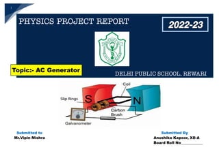
- 7. 7 Construction of A.C. Generator The A.C. Generator is consist of four main parts: ➢ THE COIL (ARMATURE) : A rectangular coil ABCD consist of a large number of turns of copper bound over a soft iron core is called armature. The soft iron core is used to increase the magnetic flux. An armature is defined as the component of an electric machine (i.e. a motor or generator) that carries alternating current (AC). The armature conducts AC even on DC (Direct Current) machines via the commutator (which periodically reverses current direction) or due to electronic commutation, (e.g. in a brushless DC motor). The armature provides housing and support to the armature winding. In electrical machines, the magnetic field is generated by a permanent magnet or electromagnet. The armature winding interacts with the magnetic field formed in the air gap. The stator can be a rotating part (rotor) or stationary part (stator).
- 8. 8 ➢ MAGNETIC FIELD : It is usually a permanent sponge magnet having concave poles. The armature is rotated of a magnet so that axis of the armature is perpendicular to magnetic field lines. The rotor structure can consist of a ring of magnetic iron with magnets mounted on its surface. A magnet material such as neodymium- boron-iron or samarium-cobalt can provide a magnetic flux density in the air gap comparable to that produced with field windings, using a radial depth of magnet of less than 10 millimeters. Other magnet materials such as ferrite can be used, but with a considerable reduction in air-gap flux density and a corresponding increase in generator dimensions. Permanent-magnet generators are simple in that they require no system for the provision of field current. They are highly reliable. They do not, however, contain any means for controlling the output voltage. A typical example of use is with a wind turbine where the generator output of variable voltage and frequency is supplied to a power system through an electronic frequency converter.
- 9. 9 ➢ SLIP RINGS : The function of slip ring in an AC generator is that these are the hollow rings that are connected to the ends of the armature coil. They help in rotation of the coil. Also, they provide electric contact with the brushes. A slip ring is an electromechanical device that allows the transmission of power and electrical signals from a stationary to a rotating structure. A slip ring can be used in any electromechanical system that requires rotation while transmitting power or signals. It can improve mechanical performance, simplify system operation and eliminate damage-prone wires dangling from movable joints. These rings are commonly found i n s l i p r i n g m o t o r s , e l e c t r i c a l generators for alternating current (AC) systems and alternators and in packaging machinery, cable reels, and wind turbines. Typically, a slip ring consists of a stationary graphite or metal contact (brush) which rubs on the outside diameter of a rotating metal ring. As the metal ring turns, the electric current or signal is conducted through the stationary brush to the metal ring making the connection.
- 10. 10 ➢ BRUSHES : The brushes B1 & B2 are just touch the slip rings. They are not rotating with the coil and these brushes leads to the output of load resistance. A carbon brush is a component used to conduct electrical current between the stationary and rotating parts of a motor. In a generator or motor, the commutator rotates on a shaft and the fixed carbon brush rides on it to permit the flow of electricity and complete a circuit. Brush History Originally, brushes were made of wire and looked like standard wire brushes. However, the wire brushes tended to wear away the commutator and suffered other run-time issues. The introduction of graphite provided brushes that allowed a more uniform shift of current between commutator segments. Graphite carbon brushes also wear, sparing the commutator. Carbon brushes are available in four main grade categories: carbon graphite, electro graphitic, graphite, and metal graphite. Material types are matched to the demands of the motor or generator as well as the operational environment. Brushes are customized based on dimensions, bevels, seating, shunts and terminals, plates and hard tops, and other special features.
- 11. 11 Theory Of A.C. Generator AC generators are widely used to produce AC voltage. To understand how these generators operate, the basic theory of operation must first be understood. Theory of Operation AC generators work on the principle of Faraday’s law of electromagnetic induction. This law states that electro motive force is generated in a current carrying loop that is placed in a uniform magnetic field. Whenever a coil is rotated about its axis perpendicular to the uniform magnetic field, the magnetic flux in the coil changes and an induced emf is set up across its ends. When the coil in the generator starts moving, the arm AB starts moving upwards and the arm CD moves downwards. These arms start cutting the magnetic lines of force therefore, by Fleming’s right hand rule, the induced current set up in these arms is along the direction of AB and CD.
- 12. 12 Let us consider a coil of N turns and area A that is rotated at constant angular velocity in a magnetic field of B as shown in the figure. When the normal to the coil is at an angle θ, magnetic flux is generated in the coil. This flux is given by, ϕ=BANcosθ We know that, E=−dϕ / dt Substituting the value of ϕ in above equation We get, ⇒E=−dBANcosθ/ dt Now, we know that θ=ωt Therefore, ⇒E=−dBANcosωt /dt On solving, ⇒E=BANωsinωt We know that, the maximum value for induced emf will be obtained when ⇒θ=ωt=90⁰ Therefore, the maximum value of induced emf will be E=BANω . Note: The machine that generates electrical energy by converting the mechanical energy is known as an AC generator. The
- 13. 13 electrical energy that is generated is in the form of an alternating current as a sinusoidal waveform. The mechanical energy that is to be converted is usually supplied through combustion engines, turbines,etc. The strong magnetic field is produced by a current flow through the field coil of the rotor. The field coil in the rotor receives excitation through the use of slip rings and brushes. Two brushes are spring-held in contact with the slip rings to provide the continuous connection between the field coil and the external excitation circuit. The armature is contained within the windings of the stator and is connected to the output. Each time the rotor makes one complete revolution, one complete cycle of AC is developed. A generator has many turns of wire wound into the slots of the rotor. The magnitude of AC voltage generated by an AC generator is dependent on the field strength and speed of the rotor. Most generators are operated at a constant speed; therefore, the generated voltage depends on field excitation, or strength. The frequency of the generated voltage is dependent on the number of field poles and the speed at which the generator is operated, as indicated in below Equation. F= 120/NP N = 12 x f / P Where f = frequency (Hz) P = total number of poles N = rotor speed (rpm) 120 = conversion from minutes to seconds and from poles to pole pairs
- 14. 14
- 15. 15 Working of A.C. Generator The coil is rotated in anti-clock wide direction. In the first half rotation the arm AB is moving outward and CD is moving inward. So the e.m.f. is induced in the arm AB from A to B. And in the arm CD from C to D. After half rotation (in the second half). The arm CD is moving outward and AB is moving inward. In this time current is induced in arm CD from D to C. And in arm AB from B to A. In the second half rotation the current direction is changing so in this generator AC is produced. Expression for Instantaneous e.m.f. Produced: Let position of the coil at any time t. It's make angle q an angle with vertical. If w is uniform angular speed of the coil. Then q = wt B be the strength of magnetic field n be the number of turns in the coil and A area of the coil then magnetic flux with the coil in this position is given by: f = nBA Cos q = nBA Cos wt. differentiate w.r.t. time. = nBA (-Sin wt) w = -nBA w Sin wt e = = -(-nBA w Sin wt) maximum value of e.m.f. say e0 e = e0 Sin wt.
- 16. 16 Applications of AC Generator ➢ Bicycles ➢ Electric scooters ➢ Microwaves ➢ Sailboats ➢ Airplanes ➢ Hydro Electric Dam’s ➢ Windmills
- 17. 17 Advantages of AC Generator over DC Generator A direct current generator or DC generator is a device that converts mechanical energy into direct current electricity. The electricity produced by this device is dynamic and has no up and down peaks like an AC generator.
- 18. 18 Conclusion So, in this chapter, we learned that an AC generator is a device that converts mechanical energy into electrical energy in the form of alternating EMF or alternating current. It is based on the principle of electromagnetic induction. In AC generators the supply of mechanical energy is supplied by combustion engines, gas turbines, and steam turbines. The working principle of the AC generator is based on Faraday’s Law of electromagnetic induction. The law states that the current will be induced in the conductor when placed in the magnetic field. AC generators have many uses in your day-to-day life. It is observed that this particular topic carries five marker questions in the CBSE Board examination.
- 19. 19 BIBLIOGRAPHY ❖CBSE Lab Manual ❖Help of Physics Teacher ❖NCERT Textbooks ❖Websites :- www.google.com www.wikipedia.com www.pngegg.com ------♣------