1. DRAFTING MANUAL
Section 4.9.1
Update 69 Gears (Bevel and Hypoid) Page 1
Gary Whitmire Drafting Practice August, 2003
1.0 General
This section provides the basis for uniformity in engineering gears drawings and their technical data for gears
with intersecting axes (bevel gears), and nonparallel, nonintersecting axes (hypoid gears). It also discusses the
method of specifying matched sets on a gear drawing.
2.0 Purpose
It is the purpose of this section to provide formats, nomenclature, and definitions. The minimum data for the
various gear types are defined. Where additional data are required, methods for specifying these data are shown.
Slight deviations for critical applications are allowed, provided general formats are maintained.
2.1 Examples - Various types of gears are illustrated by sample drawings.
2.2 Dimensioning and Notes - Illustrations show only those dimensions which control the gear teeth and their
relation to the specified mounting. All other dimensions and specifications shall conform to recommended
drafting practice. Dimensional values show the number of decimal places recommended in each instance.
Where required to assure calculations, such as for pin measurement or master gears, accurate to the fourth place to
the right of the decimal point, it is necessary to specify the base diameter, pitch diameter, helix angle, and non-
whole number diametral pitch to eight or seven significant places.
2.2.1 Angular Dimensions - All angular dimensions shall be expressed in degrees and decimal portions thereof.
(Where desired, the angle may be given in degrees, minutes and seconds.)
3.0 Applicable Documents
The following reference documents contain additional information and should be used when applicable.
ASME Y14.38 Abbreviations and Acronyms
ASME Y14.1 Decimal Inch. Drawing Sheet Sizes and Format
ASME Y14.1M Metric Drawing Sheet Sizes and Format
ASME Y14.2M Line Conventions and Lettering
ASME Y14.3M Multiview and Sectional View Drawings
ASME Y14.5M Dimensioning and Tolerancing
ASME Y14.36M Surface Texture Symbols
AGMA 112.04 Gear Nomenclature - Terms, Definitions, Symbols, and Abbreviations
Genium Publishing Corporation
2. DRAFTING MANUAL
Section 4.9.1
Update 69 Gears (Bevel and Hypoid) Page 2
Gary Whitmire Drafting Practice August, 2003
4.0 Gear Drawing Practices
4.1 Arrangement - The gear drawing shall clearly illustrate the general configuration. The method of
manufacture, the quantities involved and the desired inspection method may influence the method of
dimensioning. Illustrations of various gear configurations are provided for guidance only and are not mandatory.
4.1.1 Gear Data - Gear data shall be grouped as illustrated and shall be presented in the order shown. The location
of the gear data on the drawing is optional.
4.1.2 Specifying a Diameter – For external gears only, the major diameter is specified as the outside diameter and
the minor diameter is specified as the root diameter. For internal gears the major diameter is specified as the root
diameter and the minor diameter is specified as the inside diameter. This is in keeping with present usage in some
segments of the gear industry.
4.2 Manufacturing Method - The drawing shall clearly depict the product without reference to a manufacturing
or inspection method. This rule may be disregarded only where special situations are involved which do not lend
themselves to exact specifications and tool inspection information is necessary for control.
4.3 Drawing Title - For identification purposes, the title should include the word pinion or gear as applicable.
4.4 Straight Bevel Gear Teeth
4.4.1 Straight bevel gear and pinion teeth are drawn as shown in Figure 1. The mounting distance shown on the
drawing is an assembly dimension and is specified as a reference dimension.
Genium Publishing Corporation
3. DRAFTING MANUAL
Section 4.9.1
Update 69 Gears (Bevel and Hypoid) Page 3
Gary Whitmire Drafting Practice August, 2003
(X.XXX)
XX.XX˚ XX.XX˚
XX.XX˚ XX.XX˚
See note 1
X.XXX
X.XXX
See note 1
XX.XX˚
XX.XX˚
See note 1
A
FACE APEX
X.XXXX X.XXX
X.XXXX X.XXX
AXIS OF
MATING
MEMBER
X.XXX
X.XXX
See note 1
.XXX A
.XXX
.XXX
(.XXX)
(X.XXXX)
Mounting Distance
Note 1: When face angle distance and back angle distance (See Figure 9) are
used for dimensioning the gear blank, the face angle and the back angle should
be given as reference dimensions on the drawing without a tolerance.
Figure 1. Straight Bevel Gear/Pinion
4.4.2 Gear data not included in Figure 1 are tabulated on the drawing as shown in Figure 2. The drawing must
also show material and heat treatment specifications.
NUMBER OF TEETH XX
DIAMETRAL PITCH (See note 1) (XX.XXX)
PRESSURE ANGLE (XX.XX°)
PITCH DIAMETER (X.XXXX)
Genium Publishing Corporation
4. DRAFTING MANUAL
Section 4.9.1
Update 69 Gears (Bevel and Hypoid) Page 4
Gary Whitmire Drafting Practice August, 2003
ADDENDUM (.XXX) (See note 2)
WORKING DEPTH (.XXX) (See note 2)
WHOLE DEPTH .XXX-.XXX (See note 2)
THEORETICAL OUTSIDE DIAMETER (X.XXX) (See note 2)
THEORETICAL CROWN TO BACK (X.XXX) (See note 2)
PITCH ANGLE (XX.XX°) (See note 2)
ROOT ANGLE (XX.XX°)
CIRCULAR THICKNESS (.XXXX) (See note 2)
MEAN MEASURING ADDENDUM .XXX (See note 2)
MEAN MEASURING THICKNESS .XXX-.XXX (See note 2)
NORMAL BACKLASH WITH MATE .XXX-.XXX (See note 2)
BACKLASH VARIATION TOLERANCE (See note 3) .XXXX
SHAFT ANGLE (XX.XX°)
FILLET RADIUS .XXX-.XXX (See note 2)
RUNOUT TOLERANCE (See note 3) .XXXX
PITCH TOLERANCE (See note 3) .XXXX
INDEX TOLERANCE (See note 3) .XXXX
TOOTH SURFACE TEXTURE XX AA OR Ra
AGMA QUALITY CLASS XX
TOOTH FORM CONIFLEX® OR REVACYCLE®
DRIVING MEMBER PINION OR GEAR
DIRECTION OF ROTATION CW AND/OR CCW
MFG SUMMARY NUMBER XXXXXX
PART NUMBER OF MATE XXXXXXXX-X
NUMBER OF TEETH IN MATE XX
Notes 1. For metric drawings, specify module in place of diametral pitch.
2. For metric drawings, reduce by one the number of decimal places to the right.
3. See 5.18.3, 5.23 – 5.26 for when to specify these values on the gear drawing.
Figure 2. Data Specifications For Straight Bevel Gears
Genium Publishing Corporation
5. DRAFTING MANUAL
Section 4.9.1
Update 69 Gears (Bevel and Hypoid) Page 5
Gary Whitmire Drafting Practice August, 2003
4.5 Spiral Bevel Gear Teeth
4.5.1 Spiral bevel gear and pinion teeth are drawn as shown in Figure 3.
(X.XXX)
XX.XX˚ XX.XX˚
XX.XX˚ XX.XX˚
See note 1
X.XXX
X.XXX
See note 1
XX.XX˚
XX.XX˚
See note 1
FACE APEX
X.XXXX
X.XXXX X.XXX
.XXX M A X.XXX
AXIS OF
MATING
MEMBER
.XXX
.XXX
.XXX X.XXX
(.XXX)
X.XXX
See note 1
(.XXX)
(X.XXXX)
A Mounting Distance
Note 1: When face angle distance and back angle distance (See Figure 9) are
used for dimensioning the gear blank, the face angle and the back angle should
be given as reference dimensions on the drawing without a tolerance.
Figure 3. Spiral Bevel Gear/Pinion
Genium Publishing Corporation
6. DRAFTING MANUAL
Section 4.9.1
Update 69 Gears (Bevel and Hypoid) Page 6
Gary Whitmire Drafting Practice August, 2003
4.5.2 Gear data not illustrated in Figure 3 are tabulated on the drawing as shown in Figure 4. The drawing must
also show material and heat treatment specifications.
NUMBER OF TEETH XX
DIAMETRAL PITCH (See note 1) (XX.XXX)
NORMAL PRESSURE ANGLE (XX.XX°)
MEAN SPIRAL ANGLE (XX.XX°)
PITCH DIAMETER (X.XXXX)
ADDENDUM (.XXX) (See note 2)
WORKING DEPTH (.XXX) (See note 2)
WHOLE DEPTH (.XXX) (See note 2)
THEORETICAL OUTSIDE DIAMETER (X.XXX) (See note 2)
THEORETICAL CROWN TO BACK (X.XXX) (See note 2)
PITCH ANGLE (XX.XX°)
ROOT ANGLE (XX.XX°)
CIRCULAR THICKNESS (.XXXX) (See note 2)
MEAN MEASURING ADDENDUM .XXX (See note 2)
MEAN MEASURING THICKNESS .XXX-.XXX (See note 2)
MEAN MEASURING DEPTH .XXX-.XXX (See note 2)
NORMAL BACKLASH WITH MATE .XXX-.XXX (See note 2)
BACKLASH VARIATION TOLERANCE (See note 3) .XXXX (See note 2)
SHAFT ANGLE (XX.XX°)
FILLET RADIUS .XXX-.XXX (See note 2)
RUNOUT TOLERANCE (See note 3) .XXXX
PITCH TOLERANCE (See note 3) .XXXX
INDEX TOLERANCE (See note 3) .XXXX
TOOTH SURFACE TEXTURE XX AA OR Ra
AGMA QUALITY CLASS XX
TOOTH FORM GENERATED OR FORMATE® OR
HELIXFORM®
DRIVING MEMBER PINION OR GEAR
DIRECTION OF ROTATION CW AND/OR CCW
MFG SUMMARY NUMBER XXXXXX
Genium Publishing Corporation
7. DRAFTING MANUAL
Section 4.9.1
Update 69 Gears (Bevel and Hypoid) Page 7
Gary Whitmire Drafting Practice August, 2003
PART NUMBER OF MATE XXXXXXXX-X
NUMBER OF TEETH IN MATE XX
V AND H CHECK IN THOUSANDTHS OF AN INCH (OR HUNDREDTHS OF A MILLIMETER) FOR
FINISHED GEARS (See note 4).
Gear Convex Toe Heel Total
V XX XX XX
H XX XX XX
Gear Concave Toe Heel Total
V XX XX XX
H XX XX XX
Notes 1. For metric drawings, specify module in place of diametral pitch.
2. For metric drawings, reduce by one the number of decimal places to the right.
3. See 5.18.3, 5.23 – 5.26 when to specify these values on the gear drawing.
4. May be specify on matched set drawing. (See Figure 8)
Figure 4. Data Specifications For Straight Bevel Gears
Genium Publishing Corporation
8. DRAFTING MANUAL
Section 4.9.1
Update 69 Gears (Bevel and Hypoid) Page 8
Gary Whitmire Drafting Practice August, 2003
4.6 Hypoid Gear Teeth
4.6.1 Hypoid pinion and gear teeth are drawn as shown in Figures 5 and 6, respectively.
XX.XX˚
XX.XX˚
See note 1 (.XXX)
XX.XX˚
X.XXX XX.XX˚
X.XXX See note 1
A B See note 1
CROSSING POINT
FACE APEX
X.XXX X.XXX
X.XXX X.XXX
ROOT APEX
.XXX
.XXX
See note 1
X.XXXX AXIS OF
X.XXXX .XXX MATING
.XXX MEMBER
(.XXX)
.XXX A - B
(X.XXXX)
Mounting Distance
Note 1: When face angle distance and back angle distance (See Figure 9) are
used for dimensioning the gear blank, the face angle and the back angle should
be given as reference dimensions on the drawing without a tolerance.
Figure 5. Hypoid Pinion
Genium Publishing Corporation
9. DRAFTING MANUAL
Section 4.9.1
Update 69 Gears (Bevel and Hypoid) Page 9
Gary Whitmire Drafting Practice August, 2003
X.XXX
X.XXX
See note 1
XX.XX∞
XX.XX∞
See note 1
XX.XX∞
XX.XX∞
See note 1
X.XXX
X.XXX FACE APEX
See note 1
X.XXXX PITCH APEX
X.XXXX
.XXX M A CROSSING POINT
ROOT APEX
X.XXX
X.XXX
AXIS OF
MATING
MEMBER
XX.XX∞
XX.XX∞
.XXX
.XXX
.XXX
(.XXX)
A
(.XXX)
.XXX
.XXX
(X.XXXX)
Mounting Distance
Note 1: When face angle distance and back angle distance (See Figure 9) are
used for dimensioning the gear blank, the face angle and the back angle should
be given as reference dimensions on the drawing without a tolerance.
Figure 6. Hypoid Gear
4.6.2 Gear data not included in Figures 5 and 6 are tabulated on the drawing as shown in Figure 7. The drawing
must also show material and heat treatment specifications. Distances from the pitch apex for the gear member
only, face apex, and root apex to the crossing point (centerline of the mating member) are included as reference
Genium Publishing Corporation
10. DRAFTING MANUAL
Section 4.9.1
Update 69 Gears (Bevel and Hypoid) Page 10
Gary Whitmire Drafting Practice August, 2003
dimensions. Values are positive when the apex is beyond the crossing point and negative when the apex lies
between the gear and crossing point. The pitch diameter and pitch angle are specified on the gear member only.
NUMBER OF TEETH XX
DIAMETRAL PITCH (See note 1) (XX.XXX)
NORMAL PRESSURE ANGLE – GEAR CONVEX (XX.XX°)
NORMAL PRESSURE ANGLE – GEAR CONCAVE (XX.XX°)
MEAN SPIRAL ANGLE (XX.XX°)
HAND OF SPIRAL LH OR RH
PINION OFFSET (XX.XX°)
DIRECTION OF OFFSET AC OR BC
PITCH DIAMETER (GEAR ONLY) (X.XXXX)
ADDENDUM (GEAR ONLY) (.XXX) (See note 2)
WORKING DEPTH (.XXX) (See note 2)
WHOLE DEPTH (.XXX) (See note 2)
THEORETICAL OUTSIDE DIAMETER (X.XXX) (See note 2)
THEORETICAL CROWN TO BACK (X.XXX) (See note 2)
PITCH ANGLE (GEAR ONLY) (XX.XX°)
ROOT ANGLE (XX.XX°)
FACE APEX TO CROSSING POINT (.XXX) (See note 2)
PITCH APEX TO CROSSING POINT (GEAR ONLY) (.XXX) (See note 2)
ROOT APEX TO CROSSING POINT (.XXX) (See note 2)
MEAN MEASURING ADDENDUM .XXX (See note 2)
MEAN MEASURING THICKNESS .XXX-.XXX (See note 2)
MEAN MEASURING DEPTH .XXX-.XXX (See note 2)
NORMAL BACKLASH WITH MATE .XXX-.XXX (See note 2)
BACKLASH VARIATION TOLERANCE (See note 3) .XXXX (See note 2)
SHAFT ANGLE (XX.XX°)
FILLET RADIUS .XXX-.XXX (See note 2)
RUNOUT TOLERANCE (See note 3) .XXXX
PITCH TOLERANCE (See note 3) .XXXX
INDEX TOLERANCE (See note 3) .XXXX
TOOTH SURFACE TEXTURE XX AA OR Ra
Genium Publishing Corporation
11. DRAFTING MANUAL
Section 4.9.1
Update 69 Gears (Bevel and Hypoid) Page 11
Gary Whitmire Drafting Practice August, 2003
AGMA QUALITY CLASS XX
TOOTH FORM GENERATED OR FORMATE® OR
HELIXFORM®
DRIVING MEMBER PINION OR GEAR
DIRECTION OF ROTATION CW AND/OR CCW
MFG SUMMARY NUMBER XXXXXX
PART NUMBER OF MATE XXXXXXXX-X
NUMBER OF TEETH IN MATE XX
V AND H CHECK IN THOUSANDTHS OF AN INCH (OR HUNDREDTHS OF A MILLIMETER) FOR
FINISHED GEARS (See note 4).
Gear Convex Toe Heel Total
V XX XX XX
H XX XX XX
Gear Concave Toe Heel Total
V XX XX XX
H XX XX XX
Notes 1. For metric drawings, specify module in place of diametral pitch.
2. For metric drawings, reduce by one the number of decimal places to the right.
3. See 5.18.3, 5.23 – 5.26 when to specify these values on the gear drawing.
4. May be specify on matched set drawing. (See Figure 8)
Figure 7 – Data Specifications For Hypoid Gears
4.7 Matched Sets
4.7.1 Bevel and hypoid gears are frequently maintained as a matched set in assembly. See Figure 8.
4.7.2 Gear sets that have a common factor, should have a specific marking on mating teeth to assure reassembly
of the gears as originally matched. See Figure 8.
4.7.3 Matched set drawings shall contain the following note:
THIS GEAR IS PART OF A MATCHED SET WITH MATE NO. XXXXXX. EACH MATCHED SET IS TO
BE MAINTAINED AS A SET AFTER IDENTITY IS DETERMINED. MARKED TEETH (NON-HUNTING)
MUST BE ASSEMBLED AS SHOWN.
Genium Publishing Corporation
12. DRAFTING MANUAL
Section 4.9.1
Update 69 Gears (Bevel and Hypoid) Page 12
Gary Whitmire Drafting Practice August, 2003
pinion
Pinion and Gear to be matched in pairs
for proper tooth contact and backlash
and measured mounting distance on
these surfaces. See note 1.
(X.XXXX)
GEAR MOUNTING DISTANCE
gear
(X.XXXX)
PINION MOUNTING DISTANCE
DRIVING MEMBER PINION OR GEAR
DIRECTION OF ROTATION CW AND / OR CCW
MFG SUMMARY NUMBER XXXXXX
PART NUMBER OF DRIVER XXXXXX
PART NUMBER OF DRIVEN XXXXXX
V AND H CHECK IN THOUSANDTHS OF AN INCH (OR HUNDREDTHS OF A MILLIMETER) FOR
FINISHED GEAR SET
GEAR CONVEX TOE HEEL TOTAL GEAR CONCAVE TOE HEEL TOTAL
V XX XX XX V XX XX XX
H XX XX XX H XX XX XX
X
X X
MARKED TEETH MUST BE ASSEMBLED AS SHOWN
NOTES:
1. On even or multiple ratios, a pair of meshing teeth should be etched ìXî when in mesh in order that they may be
assembled in the same running position as when manufactured. See paragraph 4.8.2.
2. For metric drawings, the number of places to the right of the decimal point should be reduced by one.
Figure 8. Data Specifications for Bevel gear Matched Set
5.0 Gear Tooth Nomenclature
The following nomenclature is general terms used on the gear drawing. A more complete explanation of terms,
definitions and illustrations is given in American Standard for Gear Nomenclature, ANSI/AGMA 112.05,
published by the American Gear Manufacturers Association.
Genium Publishing Corporation
13. DRAFTING MANUAL
Section 4.9.1
Update 69 Gears (Bevel and Hypoid) Page 13
Gary Whitmire Drafting Practice August, 2003
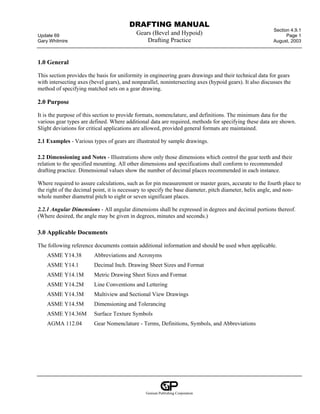
5.1 Axial Plane - A plane that contains the gear axis. Figure 9 is an illustration of the axial plane of a bevel gear.
Figure 10 (lower view) is an illustration of the axial plane of a hypoid gear.
Genium Publishing Corporation
14. DRAFTING MANUAL
Section 4.9.1
Update 69 Gears (Bevel and Hypoid) Page 14
Gary Whitmire Drafting Practice August, 2003
Mounting Distance
Crown to Crossing Point Crown to
Back
Front Crown
Angle
Heel
Toe
Mounting
Surface
Outer Cone Distance Crossing
point
Mean Cone Distance See note 1
Face Width Uniform
Clearance
Dedendum
Angle
PINION
Face Angle Face Apex
of Blank
Root Angle Shaft Angle
A See note 2
Transverse
Back Angle Plane
GEAR
Pitch Element
A
Face Angle Distance Pitch
Angle
Pitch Diameter
Outside
Diameter
Back Cone
Distance
Back Angle
Distance
Back Cone
NOTE:
1. The pitch apex and the root apex may or may not coincide depending on individual gear design.
2. See Figure 10 for developed view of A-A.
Figure 9. Bevel Gear Nomenclature – Axial Plane
Genium Publishing Corporation
15. DRAFTING MANUAL
Section 4.9.1
Update 69 Gears (Bevel and Hypoid) Page 15
Gary Whitmire Drafting Practice August, 2003
Addendum Dedendum
Back Cone Distance
Circular Thickness
Backlash
Tooth Profile
Clearance
Top Land
Circular Pitch
Working
Depth
Whole Depth
Root Land
Tooth Fillet
SECTION A-A
Figure 10. Bevel Gear Nomenclature – Transverse Plane at Outside Diameter
5.2 Pitch Plane - A plane tangent to the gear pitch surface. For bevel gears, the pitch plane is tangent to the pitch
cone.
5.3 Transverse Plane - A plane perpendicular to both the axial plane and the pitch plane. Figure 11 illustrates the
gear nomenclature in the transverse plane of a bevel gear.
5.4 Normal Plane - A plane perpendicular to the pitch plane and containing a line normal to the tooth surface at
the pitch point. On bevel gears, it usually refers to the plane that passes through the mean point (the section at the
center of the face width). Figure 12 illustrates the gear nomenclature in the normal plane of a bevel gear.
5.5 Tangent Plane - A plane tangent to the tooth surface at a point of contact. As used in the standard, the tangent
plane is taken at the mean point.
5.6 Mean Point - The point on the intersection of the tooth surface with the pitch surface at the middle of the
theoretical face width of a bevel or hypoid gear. See Figures 9 and 13.
Genium Publishing Corporation
16. DRAFTING MANUAL
Section 4.9.1
Update 69 Gears (Bevel and Hypoid) Page 16
Gary Whitmire Drafting Practice August, 2003
Back Angle Distance
Root Apex to
Crossing Point
Root Angle
Face Apex Offset
to Crossing
Point
Outside
Diameter
Crossing
Point
Face Angle Face Angle Distance
Face Width
Back Angle
Front Crown to Crossing Point
Crown to Crossing Point
nce
ista
o ne D
er C Crossing
Out Crossing
Point Point
Face Angle
Face Width
Shaft Angle Pinion Crown to
Crossing Point
Root Angle Gear
Back Angle Pitch Angle Mounting
Distance
Gear
Face Angle Distance ance
gle Dist
k An
Bac
Pitch Diameter
Outside Diameter
Figure 11. Hypoid Gear Nomenclature – Axial Plane
Genium Publishing Corporation
17. DRAFTING MANUAL
Section 4.9.1
Update 69 Gears (Bevel and Hypoid) Page 17
Gary Whitmire Drafting Practice August, 2003
Normal
Backlash
Measuring
Thickness
Measuring
Addendum
Measured Whole
Depth
Figure 12. Bevel Gear Nomenclature – Normal Plane at the Mean Point
Genium Publishing Corporation
18. DRAFTING MANUAL
Section 4.9.1
Update 69 Gears (Bevel and Hypoid) Page 18
Gary Whitmire Drafting Practice August, 2003
5.7 Tooth Trace - The curve of intersection between the pitch surface and tooth surface. See Figure 13.
Mean Point of Tooth
Convex Side of Tooth
Tooth Trace
Pitch Apex
Mean Spiral Angle
Element of
Pitch Cone
Concave Side of Tooth
Section Through Tooth
on Pitch Cone
Figure 13. Mean Spiral Angle
5.8 Diametral Pitch - The ratio of the number of teeth to the pitch diameter in inches. Unless otherwise specified,
the transverse diametral pitch (specified in the transverse plane) is implied. For hypoid gears, it is the transverse
diametral pitch of the gear member.
5.9 Module (Metric) - The ratio of the pitch diameter in millimeters to the number of teeth. Unless otherwise
specified, the transverse module (specified in the transverse plane) is implied. For hypoid gears, it is the
transverse module of the gear member.
5.10 Pressure Angle - The angle at the pitch point between a line normal to the tooth profile and the pitch plane.
See Figure 14. Unless otherwise specified for bevel and hypoid gears, the normal pressure angle (measured in the
normal plane at the mean point) is implied. The normal pressure angle is that angle in the normal plane at the
pitch point between the tangent plane and a radial line to the gear center. On most types of gears the pressure
angles on both sides of the gear tooth profile are equal. An exception to this is in designs of gears with buttress
Genium Publishing Corporation
19. DRAFTING MANUAL
Section 4.9.1
Update 69 Gears (Bevel and Hypoid) Page 19
Gary Whitmire Drafting Practice August, 2003
teeth, such as hypoids. Hypoid gear teeth, because of their asymmetric relationship, do not naturally have equal
pressure angles on their two sides. With spiral bevel gears, the designer may deliberately unbalance the pressure
angles to produce a buttressed tooth. On spiral bevel and hypoid gears, the teeth are cut with lengthwise curvature.
One tooth surface is concave; the other is convex. These two terms are used to identify the two sides of the gear
teeth. See Figure 13.
Radial Line
Through
Pitch Point Trace of
Tangent Plane
Pressure Angle
Pitch Plane
Pitch Point
Figure 14. Pressure Angle
5.11 Spiral Angle - The angle between the tooth trace and an element of the pitch cone. See Figure 13. The spiral
angle is at the mean point, unless otherwise specified. On hypoid gears, the spiral angles on gear and mating
pinion are unequal.
5.12 Hand of Spiral - The direction of inclination of the teeth as viewed by an observer looking at the face of the
gear. A left-hand spiral is one in which the outer half of the teeth are inclined in a counterclockwise direction. A
right-hand spiral is one in which the outer half of the teeth are inclined in a clockwise direction. See Figure 15.
With the exception of a few relatively rare hypoid gear designs, a gear and mating pinion have opposite hands of
spiral.
Genium Publishing Corporation
20. DRAFTING MANUAL
Section 4.9.1
Update 69 Gears (Bevel and Hypoid) Page 20
Gary Whitmire Drafting Practice August, 2003
Offset
Offset
(a) (b)
Offset Below Center LH Pinion RH Gear
Offset
Offset
(c) (d)
Offset Above Center RH Pinion LH Gear
Figure 15. Hand of Spiral and Pinion Offset
5.13 Hypoid Pinion Offset - The perpendicular distance between the axes of a hypoid gear set. Hypoid gears and
pinions, shown in Figure 15(a) and (b), are referred to as having a pinion offset “below center,” while those
shown in Figure 15(c) and (d) have a pinion offset “above center.” The direction of pinion offset is determined by
viewing the face of the gear with the pinion at the right.
5.14 Direction of Rotation - The direction of rotation is determined by viewing the gear or pinion from its back.
The direction of rotation of gear and mating pinion are either clockwise or counterclockwise and always opposite
to each other.
5.15 Tooth Form - The shape of the tooth profile. Since bevel and hypoid gears are manufactured with a variety
of tooth forms, it is essential to specify the desired form on the gear drawing.
Genium Publishing Corporation
21. DRAFTING MANUAL
Section 4.9.1
Update 69 Gears (Bevel and Hypoid) Page 21
Gary Whitmire Drafting Practice August, 2003
5.15.1 Generated - A tooth form where both members have tooth profiles produced with a relative motion
between the cutting tool and the work in addition to the cutting action.
5.15.2 Non-Generated - A tooth form where the gear tooth profile is produced without a generating motion
between the cutting tool and the work. The mating pinion must be generated.
5.15.3 CONIFLEX® - A trade name applied to generated straight bevel gears whose teeth have lengthwise
crowning.
5.15.4 REVACYCLE® - A trade name applied to straight bevel gears produced with circular arc tooth profiles.
5.15.5 FORMATE® - A trade name applied to non-generated spiral and hypoid gears in which the tooth profiles
are straight. The mating pinions are generated to be conjugate to the gears.
5.15.6 HELIXFORM® - A trade name applied to non-generated spiral bevel and hypoid gears in which the tooth
surfaces are heicoidal in form.
5.15.7 ZEROL® - A trade name applied to spiral bevel gears with zero spiral angle at some point along the tooth
length.
5.16 Depthwise Tooth Taper - The difference in tooth depth at the inner and outer ends of the teeth. Standard
depthwise tooth taper refers to gears in which the tooth depth is proptiena1 to the distance from the pitch apex.
Zero depthwise taper refers to teeth with constant depth. Frequently conical gears are designed with “tilted root
lines”. This generally refers to a depthwise tooth taper which is deeper at the outer end of the tooth and shallower
at the inner end of the tooth than that resulting from standard taper. Tilting the root lines is done to improve the
point width of the cutting tools.
5.17 Clearance - The space between the top land of the tooth of one gear and the root land of the mating gear.
See Figures 11 and 12.
5.18 Backlash - The space between mating tooth surfaces. For purposes of measurement and calculation,
backlash is the amount by which the width of a tooth space exceeds the thickness of an engaging tooth. Numerical
values of backlash on bevel and hypoid gears are measured at the tightest point of mesh on the pitch circle at the
outer end of the tooth with gears assembled at their specified mounting distances. See Figure 12. Unless otherwise
specified, the term backlash denotes normal backlash; that is, backlash measured in a direction perpendicular to
the tooth surface.
5.18.1 Backlash Tolerance - The allowable variation in the backlash measured at the tightest point of mesh
among all pairs of gears of a given population as a result of tooth size variation. Backlash tolerance is used as a
control of tooth size in production and is specified on the drawing.
Genium Publishing Corporation
22. DRAFTING MANUAL
Section 4.9.1
Update 69 Gears (Bevel and Hypoid) Page 22
Gary Whitmire Drafting Practice August, 2003
5.18.2 Backlash Variation - The difference in backlash between the tightest and loosest points of mesh in one
pair of gears as a result of runout, index variation, and profile variation.
5.18.3 Backlash Variation Tolerance - The allowable variation in backlash in a single pair of gears. Backlash
variation tolerance is only specified if backlash variation is critical.
5.19 Circular Thickness - The length of arc between the two sides of a gear tooth on the pitch circle. It is the
transverse circular thickness at the outer ends of the teeth. See Figure 11.
5.20 Measuring Addendum - The height from the top of the tooth to the chord subtending the circular-thickness
arc in the normal plane. The mean measuring addendum is the value at the center of the tooth length.
5.21 Measuring Thickness - The length of the chord subtending a circular-thickness arc in the normal plane. The
mean measuring thickness is the value used at the center of the tooth length.
5.22 Mean Measuring Depth - The depth of the tooth at the center of the tooth length.
5.23 Runout Tolerance - The total allowable variation of the distance between a surface of revolution and an
indicated surface measured perpendicular to the surface of revolution. Unless otherwise specified, it refers to
radial runout of the gear teeth; that is, in a direction perpendicular to the axis of gear rotation. This value is
specified on the drawing when AGMA quality class numbers are not available.
5.24 Pitch Tolerance - The difference between the pitch and the measured distance between any two adjacent
teeth. This value is specified on the drawing for gears requiring high accuracy.
5.25 Index Tolerance - The displacement of any tooth from its theoretical angular or linear position relative to a
datum tooth. This value is specified on the drawing for gears used for accurate positioning, such as index drives.
5.26 Composite Tolerance - Tooth-to-tooth composite tolerance and total composite tolerance may be specified
in place of runout tolerance and pitch tolerance for gears of 20 diametral pitch and finer. These values are
specified on the drawing when AGMA quality class numbers are not available.
5.27 Tooth Surface Texture - The texture of the finish on the working tooth surface of a gear tooth; expressed
either as an arithmetical average deviation (AA) or an arithmetical mean deviation (Ra).
5.28 AGMA Quality Class - The classification number established by the American Gear Manufacturers
Association to designate the quality requirements of a gear. See AGMA 390.03 - AGMA Gear Handbook,
Volume 1, Gear Classification, Materials and Measuring Methods For Unassembled Gears.
5.29 V and H Check - A check used for production control of the tooth contact pattern on gears after sample
gears have been established which are known to function properly. The V and H check gives the relative vertical
(V) and horizontal (H) displacements on a testing machine to position the tooth contact pattern at both the inner
Genium Publishing Corporation
23. DRAFTING MANUAL
Section 4.9.1
Update 69 Gears (Bevel and Hypoid) Page 23
Gary Whitmire Drafting Practice August, 2003
(toe) and outer (heel) end of the tooth while maintaining the contact pattern in the middle of the tooth profile. For
control purposes, the tooth contact pattern should duplicate the pattern on the sample pair of gears when similarly
positioned in the testing machine. These data are optional on a gear drawing and specified when a satisfactory
development has been achieved. See Figures 4 and 7.
5.30 Face Angle Distance - The perpendicular distance from the intersection of the gear axis with the locating
surface at the back of a bevel or hypoid gear to the face cone element. See Figures 9 and 10.
5.31 Back Angle Distance - The perpendicular distance from the intersection of the gear axis with the locating
surface at the back of a bevel or hypoid gear to the back cone element. See Figures 9 and 10.
Genium Publishing Corporation