2024: Domino Containers - The Next Step. News from the Domino Container commu...
Con thai
1. ConThai Rice Cooker
Mr. Jaturapat Pakkanawanit
Mr. Nattapon Kumpaing
Mr. Prissada Chuachai
Mr. Sapon Pitak
Mr. Sutipong Kankua
Mr. Narubas Younuch
Mr. Kittipat Jaturapornpison
Mr. Charintorn Jareonsri
Mr. Tipakorn Sumeteenarumit
Mr. Panuwat Sangketkit
Mr. Wtsanu Thamneammai
This project Submitted in Partial Fulfillment of the
Application of industrial Electronic for Muti-Disciplinary Workshop
Department of Control System and Instrumentation Engineering
Faculty of Engineering
King Mongkut’s University of Technology Thonburi
Academic Year 2011
2. ConThai Rice Cooker
Mr. Jaturapat Pakkanawanit 53211804
Mr. Nattapon Kumpaing 53211811
Mr. Prissada Chuachai 53211819
Mr. Sapon Pitak 53211830
Mr. Sutipong Kankua 53211831
Mr. Narubas Younuch 53219012
Mr. Kittipat Jaturapornpison 54261503
Mr. Charintorn Jareonsri 54261504
Mr. Tipakorn Sumeteenarumit54261512
Mr. Panuwat Sangketkit 54261520
Mr. Wtsanu Thamneammai 54261522
This project Submitted in Partial Fulfillment of the
Application of industrial Electronic for Muti-Disciplinary Workshop
Department of Control System and Instrumentation Engineering
Faculty of Engineering
King Mongkut’s University of Technology Thonburi
Academic Year 2011
3. Chapter 1
Preface
1.1 Name of project: ConThai Rice Cooker
1.2 The origin of project
From nowadays Thai people eat rice less every year. Next Thai people consume rice
have tendency keep lower. And consumption rice in Asia have 200 kilograms per year but
number of Thai consume have 100 – 110 kilograms per year.
My world into full consumption war, have fast, convenient, save. That is necessary for
consume rice. Rice has to adapt to a wide variety of markets. Amid the hustle of urban life which
always a race against time. That’s need to use something for convenient to reduce time. So eat
rice in morning meal look like busy because it’s not support with life style that has changed. And
we got culture from west that has effect with people in town consumption. So we can see quantity
consume rice of people in town less than people in country side because limit in time.
So, this project was made for respond human behavior that was change for got more
convenient.
1.3 Objective
For develop Rice Cooker can work Variable by has basic function as follows
1.3.1 Cooking function.
1.3.2 Warm function, can set timer.
1.3.3 Boiled function, can set timer.
1.3.4 Fired function, can set timer.
4. 1-2
1.4 Procedure
Procedure is starting from search information about rice cooking at using and used then
design system of rice cooking for overview structure in this device. Detail working procedure as
follow.
1.4.1 Research Theory about rice cooking.
1.4.2 Research function and operation’s controller.
1.4.3 Design structure and circuit of rice cooking.
1.4.4 Find device of product.
1.4.5 Study writes Program by used AVR.
1.4.6 Write program go together with install circuit.
1.4.7 Develop program and Test.
1.4.8 Adjust, solve circuit and made program better.
1.4.9 Collect, conclude problem in working.
1.4.10 The results of the experiment.
1.4.11 Made report.
1.5 Period
Plan January February March April May
1 2 3 4 1 2 3 4 1 2 3 4 5 1 2 3 4 1 2 3 4 5
1. Research rice cocker
2. Hardware
3. Microcontroller
4. Design circuit
5. Buy hardware device
6. Compound circuit
7. Test circuit
8. Adjust
9. Made report
5. 1-3
1.6 Benefit
1.6.1 Can made rice cockier that proper with new life style for real use.
1.6.2 Get knowledge from work cooperation and get knowledge that have to useful.
6. Chapter 2
Theory
2.1 Power supply
2.1.1 Block Diagram
220 V
Transformer Rectifier Smoothing Regulator 5 V DC
AC Mains
Figure 2-1 Block Diagram Power supply
2.1.2 Transformer
Transformer has convert alternative current from voltage to another voltage by lose
power at less. Transformer can work with alternative only and that is the reason, why current in
home be alternative current.
Transformer convert step-up increase voltage and transformer convert step-
down decrease voltage. Almost power supply use transformer step-down for decrease voltage in
home that have height voltage (220 V) and dangerous to lower for safety.
Input inductor is called primary and output inductor is called secondary between both
doesn’t connect in current but use connection by alternative magnetic field is in transformer
magnetic coil. Draw a two line between the coil in symbol is the magnetic core.
The ratio of the number coil round is called turns ratio. It determines voltage ratio
transformer step-down. The number of round much is primary coil, connect to 220 volt is input
and output is secondary coil has number of round few, give low voltage.
7. 2-2
𝑉𝑃 𝑁𝑃
Ratio round = =
𝑉𝑆 𝑁𝑆
Vp = Primary Voltage (Input). Vs = Secondary (Output).
Np = Radians of primary inductor. Ns = Radians of secondary inductor.
2.1.3 Bridge rectifier
Current on Bridge can use four diode is connector or use brides diode readymade. This
is full wave current because used all AC current (It has positive current and negative current).
Bridge rectifiers have voltage 1.4 V. Because each diode should have voltage 0.7 V when have
induce current. More over two bridge diode have induced current simultaneously.
Figure 2-2 Bridge rectifier circuit Figure 2-3 Full wave bridge diode
2.1.4 Smoothing
Filter is grow by high value electrolytic capacitor connect to direct current. Role is
same pond, it give current to output, when smoothing is AC voltage drop. In figure is show not
filter direct current and filter direct current. Capacitor is fast evolve at peak of direct current and
Capacitor evolve to output.
8. 2-3
Figure 2-4 Show is charge and discharge of capacitor
Make direct voltage is increase to peak (1.4 × RMS). It’s example such alternative
current 6 V RMS when have full wave rectifier. It has direct current approximate 4.6 V RMS
(Loss of bridge diode rectifier is 1.4 V), When DC is pass in smoothing will increase to peak
1.4 × 4.6 = 6.4 V (DC).
Filtration is not perfect because have little voltage of capacitor when evolve. It is cause
small ripple. For general circuit, supply have ripple 10 % is able. Value of capacitor on
smoothing. It can find to equation below. If capacitor is big size will have little ripple. For half
wave direct current. Filter use over two time value of capacitor.
(5)( I o )
Capacitor for sweep 10 %, C =
(V s )(f)
Io = Output current to power supply.
Vs = Supply voltage (Vpeak of direct current isn’t filter).
f = Supply frequency AC (50 Hz).
2.1.5 Regulator
IC control voltages have constant voltage (Such 5, 12 and 15 V) or vary output voltage.
It’s call follow pass peak of current. Negative IC control voltage used for twin power supply.
General IC control that have auto overload protection and thermal protection.
Constant IC control have 3 leg and same power transistor such as IC control value
number 7805 +5 V 1 A. Show in right hand. Front have install.
9. 2-4
Figure 2-5 IC control voltage
2.2 TRIAC
TRIAC is semiconductor transistor group. It has inside structure same with DIAC, but
has one more leg. TRIAC is create for modify error SCR. When not induce current in negative
alternative current. Most application of TRIAC will use control circuit is switch connect to
alternative current. TRIAC is create high current also will must careful in drain heat. Structure of
TRIAC have 3 semiconductors is P-N-P that have 3 leg. Three leg have MT1, MT2 and G.
Figure 2-6 Structure of TRIAC Figure 2-7 Symbol of TRIAC
2.2.1 TRIC working conditions
2.2.1.1 Give positive voltage to MT2. Give negative voltage to MT1 and give positive
voltage trig to G.
2.2.1.2 Give positive voltage to MT2. Give negative voltage to MT1 and give
negative voltage trig to G.
2.2.1.3 Give negative voltage to MT2. Give positive voltage to MT1 and give
negative voltage trig to G.
10. 2-5
2.2.1.4 Give negative voltage to MT2. Give positive voltage to MT1 and give positive
voltage trig to G.
2.2.2 TRIC stops working conditions
When TRIAC induce current isn’t have to keep voltage trig to G. Because TRIAC will
continue induce current is same SCR. Stop TRIAC have 2 means.
2.2.2.1 Cutoff power supply gives to MT2 and MT1.
2.2.2.2 Decreases bias voltage is give to MT2 and MT1. It make current pass to
TRIAC lower holding current of TRIAC.
2.3 Sensor
2.3.1 Thermostat
Thermostat in digital rice cooking is difference general rice cooking. General rice
cooking consists of Lever Contact Switch and magnetic set. Diode run by magnetic deteriorate
when have high heat. But thermostat in digital rice cooking is measure temperature and send to
microcontroller for process value that control heat inductor.
2.3.2 Voltage divider circuit
Voltage divider circuit is circuits have to 2 resistance series connect between power
supply. Resistance is portion out voltage in circuit. General voltage divider circuit is develop from
Ohm’s law. Calculate is cross voltage on resistance use voltage divider will fast and be
convenient than Ohm’s law.
Figure 2-8 Show voltage divider circuit
11. 2-6
2.4 Check the power circuit
2.4.1 Block diagram
Sound detection Time delay Flash LED driver
Figure 2-9 Block Diagram check the power circuit
2.4.2 The working principle.
When, the rice cooker plug in also. The voltage sent to circuit, it’s ready for work. The
noise surrounding the rice cooker will serve as the command to start the circuit. The LED lamps
installed around. The bottom of the cooker took place light and not light. There is sound order of
the LED, on-off for 15 seconds. And it will run again when there's sound around.
2.4.3 Timing diagram
Sound
Comparator
Time Delay
15 sec.
Figure 2-10 Timing diagram check the power circuit
12. 2-7
2.4.4 The works circuit
2.4.4.1 Sound detection has received sound from microphone. And voltage sent to
Comparator circuit because output pulse signals can base bias of transistor BC184.
2.4.4.2 Time delay has delay of the circuit. Assign 15 seconds use Mono-stable
circuit from IC 555 and using output base bias transistor by BC337. Which is switch control
voltage sent to flash LED driver.
2.4.5 Flash LED driver
Flash LED driver has control on-off for LED that is LM3916. When area around the
device has sound, LED will light around 15 seconds.
2.5 Microcontroller
2.5.1 Graphic screen ET-NOKIA LCD 5110
2.7.1.1 Resolution screen 48 x 84 Dot.
2.7.1.2 High speed Serial Bus Interface communication 4.0 Mbits/s.
2.5.1.3 It has controller number PCD8544 for control.
2.5.1.4 LED Back-Light.
2.5.1.5 Run at 2.7 - 5.0 volt.
2.5.1.6 Use low power that suitable with function for battery.
2.5.1.7 Rage of temperature is -25 to +70 degree Celsius.
Figure 2-11 Display graphic ET-NOKIA LCD 5110
13. 2-8
2.5.2 AT mega 128
2.5.2.1 High effective and have low power.
2.5.2.2 High safety.
2.5.2.3 Can read flash program.
2.5.2.4 Keep data to 20 years at 85 degree Celsius.
2.5.2.5 Interface for witting SPI Program.
Figure 2.12 AT mega 128
14. Chapter 3
Circuit and Design
This chapter discusses the various parts of the circuit. And explain the function of the
circuit used in this project.
3.1 Power supply circuit
Figure 3-1 Power supply circuit
In this part we use Lm7809 to convent from transformer 12 VAC to 9 VDC current 1A
in U1 has diode for project to flow one way. In U2 use lm7805 for convent from 9VDC current
1A to 5VDC current 1A for get to use with microcontroller and U3 use lm7805 convent to 5VDC
current 1A for get to use with sensor.
15. 3-2
3.2 TRIAC circuit
Figure 3-2 TRIAC circuit
Calculate R1, when VT = 5 V, I1 = 60 mA
From VT = I1R1
5 V = (60 mA) R1
R1 = 83.33 Ω
Calculate R2, when E = 220 V, I2 = 5 mA
From E = I2R2
220 V = (5 mA) R2
R2 = 44 kΩ
17. 3-4
Calculate V3min, when RT = 111 kΩ, R3 = 10 kΩ
V3min = VT (R T )
R3
10 kΩ
= 5V(111 kΩ )
V3min = 0.4504 V
Calculate IT, when E = 5V, RT = 11 kΩ
V
IT = (R T )
T
5V
= (11 kΩ )
IT = 0.45 mA
Calculate V70°C, when R1 = 1 kΩ, R2 = 15.31 kΩ, R3 = 10 kΩ, RT = 26.31 kΩ
R
V70°C = VT (R 3 )
T
10 kΩ
= 5V(26.31 kΩ)
V70°C = 1.9004 V
Calculate V100°C, when R1 = 1 kΩ, R2 = 5.24 kΩ, R3 = 10 kΩ, RT = 16.24 kΩ
R
V100°C = VT (R 3 )
T
10 kΩ
= 5V(16.24 kΩ )
V100°C = 3.0788 V
Calculate V120°C, when R1 = 1 kΩ, R2 = 3.19 kΩ, R3 = 10 kΩ, RT = 14.19 kΩ
R
V120°C = VT (R 3 )
T
10 kΩ
= 5V(14.19 kΩ )
V120°C = 3.5236 V
Calculate V190°C, when R1 = 1 kΩ, R2 = 500 Ω, R3 = 10 kΩ, RT = 11.5 kΩ
R
V190°C = VT (R 3 )
T
10 kΩ
= 5V(11.5 kΩ )
V190°C = 4.3478 V
18. 3-5
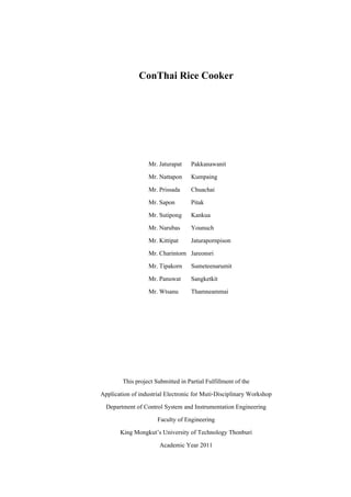
3.3.2Graph of sensor by compare resistance with temperature
Figure 3-4 The relationship between resistance and temperature.
3.4 Check sound status circuit
Figure 3-5 Show using IC 555 circuit
19. 3-6
Calculator Mono-stable circuit from
The formula Time period, T=1.1RC
Assign T=15 Sec., C=1uF
15
So R = 1.1∗1uF = 13.6364kΩ
Selection R= 14k
3.5 Touch switch circuit
Figure 3-6 IC Show using WB2080A Circuit
21. Chapter 4
Structure of Programming Controller
4.1 Operation of program
Overview of program in “Rice cooker” start from set value for user as follow.
4.1.1 Time setting.
4.1.2 Set value and Display LCD Interface.
4.1.3 Fix variable for select function in start Rice cooker.
4.1.4 Operation of program can write Flow Chart thus.
22. 4-2
START s
Cooker Boiled Stream
Set time cook If temp >100 c If temp > 100 c
Cook
False False
SW SW
Cook =
True True
on2heater
OFF heater all OFF heater all
If temp >130 c
False
SW
True
Warm
Figure 4-1 Flow chart main program
23. 4-3
START
Fried Warm Set time
If temp >190 c If time >2min Set hour
False
False
SW SW Hour +1 -1
-1
True True
OFF heater all OFF heater all Set min
6 sec.
Min +1 -1
-1
Set sec
Sec +1 -1
-1
Figure 4-2 Flow chart main program
24. Chapter 5
Experiments and conclusion
5.1 Preface
After pass programming step each part and design circuit the most important by the
way is test the circuit to find the error after that repair error.
5.2 Guidelines for tested circuit
5.2.1 Tested touch switch circuit.
5.2.2 Tested drive coil circuit.
5.2.3 Tested check sound circuit.
5.2.4 Tested sensor circuit.
5.2.5 Tested all circuit and measure temperature.
5.3 Equipment for test
Therefore, this experiment emphasis on rice cooker function and installed component
part which are;
5.3.1 Power supply: LM7805, LM7809, Capacitor.
5.3.2 Coil.
5.3.3 Triac, Isolate.
5.3.4 Sensor.
5.3.5 Touch switch.
5.3.6 Microcontroller AVR-ATMEGA128.
5.3.7 IC 3916.
5.4 Sequence Steps of Testing
5.4.1 Plug in and Microcontroller starts working.
5.4.2 Wait for rice cooker to operate (“Conthai” shows on the monitorn approximately
3 seconds).
25. 5-2
5.4.3 Press each bottom for testing both usage and function.
5.4.4 Coil testing.
5.5 Rice Cooker Function Testing
Conthai - Rice cooker could be controlled both in term of Manual system and
Automatic system. Moreover, user can verify operated order via display.
5.5.1 Testing Objective
5.5.1.1 Test the accuracy of Microcontroller that can operate as good as proper
standard
5.5.1.2 Test the accuracy of digital clock that can operate as good as proper standard
5.5.1.3 Test the accuracy of display that can operate as good as proper standard
5.5.1.4 Test the accuracy of touch switch that can operate as good as proper standard
5.5.2 Testing Task
5.5.2.1 After turn the power, rice cooker will start working by has Microcontroller as
the main function.
5.5.2.2 Microcontroller sends data and information to display monitor then our group
name, Conthai, shows on the display.
5.5.2.3 Setting time by press on time setting function bottom to adjust hour, minute
and second. After the adjustment, press time setting function bottom one more time to approve.
Sound will loud out when the confirmation complete)
5.5.2.4 Press on each function; cook, steam, fry and boil, to test touch switch. The
selected function will be displayed on display monitor and hidden light will glow out.
5.6 Conclusion
According to the testing, every components could be operated as expected and achieve
testing objective. Please turn to next unit for more information about obstacles and solution
during working process.
26. Chapter 6
Problems and suggestions
6.1 Preface
In this project has many problems, because this project use electronic device to max
efficiency for work and to divide the problem into 2 types of problems that are Software and
Hardware.
6.2 Problem and Solving
In this project has problem about Software and Hardware, so we divide the problem and solve as
follows.
6.2.1 First step I see problem that is to used hardware devices are difficult, because we
must the rice cooker have all function. And device can inside to rice cooker.
6.2.2 Second, We test to LED status circuit. When connect power supply we will find
yank voltage. It made some circuit to error. So we solve by turn on power supply before connect
the circuit after that to measure each circuit.
6.2.3 Third, when we made PCB after check line PCB. When we test circuit are find
bash about line in PCB, after we find bash about line in PCB we solve by weld line PCB.
6.2.4 The surface mouse, when we weld in PCB we don’t know it can use and check by
multi-meter.
6.2.5 Touch switch in circuits are find shield cable have ground around cable, when we
stripping the wire and weld to copper plate. Found that circuit.
6.3.6 In part microcontroller problems is FUSES attached from factory, it's not same
our experiments. It is not possible to perform experiments. It can’t possible to perform
experiments. Solution is use boards by program to list variable into experiments to fix variable 2
FUSES are same, for programming of rice cooker work.
6.5.7 The TRIAC circuit hacking problems found is calculated according to the theory.
It has excess resistance value is not able to trigger GATE output on for the TRIAC, solution is by
27. 6-2
changing the resistance less valuable so the stream flows sufficient to trigger on for the TRIAC
and selection resistor for range 1 watt.
28. Contents
Chapter 1 Preface 1-1
1.1 Name of project 1-1
1.2 The origin of project 1-1
1.3 Objective 1-1
1.4 Procedure 1-2
1.5 Period 1-2
1.6 Benefit 1-3
Chapter 2 Theory 2-1
2.1 Power supply 2-1
2.2 TRIAC 2-4
2.3 Sensor 2-5
2.4 Check the power circuit 2-6
2.5 Microcontroller 2-7
Chapter 3 Circuit and Design 3-1
3.1 Power supply circuit 3-1
3.2 TRIAC circuit 3-2
3.3 Sensor circuit 3-3
3.4 Check sound status circuit 3-5
3.5 Touch switch circuit 3-6
3.6 Microcontroller 3-7
Chapter 4 Structure of Programming Controller 4-1
4.1 Operation of program 4-1
Chapter 5 Experiments and conclusion 5-1
5.1 Preface 5-1
5.2 Guidelines for tested circuit 5-1
5.3 Equipment for test 5-1
5.4 Sequence Steps of Testing 5-1
5.5 Rice Cooker Function Testing 5-2
29. Contents (contd.)
5.6 Conclusion 5-2
Chapter 6 Problems and suggestions 6-1
6.1 Preface 6-1
6.2 Problem and Solving 6-1
Appendix A Manual
Appendix B Programming
Appendix C Datasheet
30. Figures
Figure 2-1 Block Diagram Power supply 2-1
Figure 2-2 Bridge rectifier circuit 2-2
Figure 2-3 Full wave bridge diode 2-2
Figure 2-4 Show is charge and discharge of capacitor 2-3
Figure 2-5 IC control voltage 2-4
Figure 2-6 Structure of TRIAC 2-4
Figure 2-7 Symbol of TRIAC 2-4
Figure 2-8 Show voltage divider circuit 2-5
Figure 2-9 Block Diagram check the power circuit 2-6
Figure 2-10 Timing diagram check the power circuit 2-6
Figure 2-11 Display graphic ET-NOKIA LCD 5110 2-7
Figure 2.12 AT mega 128 2-8
Figure 3-1 Power supply circuit 3-1
Figure 3-2 TRIAC circuit 3-2
Figure 3-3 Voltage divider circuit 3-3
Figure 3-4 The relationship between resistance and temperature. 3-5
Figure 3-5 Show using IC 555 circuit 3-5
Figure 3-6 IC Show using WB2080A Circuit 3-6
Figure 3-7 Show using ATMEGA12 3-7
Figure 4-1 Flow chart main program 4-2
Figure 4-2 Flow chart main program 4-3
45. GLCD_GotoXY(8,1);
sbi(PORT_SPI,DD_DC);
if (hour1==0)Put0(8);
if (hour1==1)Put1(8);
if (hour1==2)Put2(8);
if (hour1==3)Put3(8);
if (hour1==4)Put4(8);
if (hour1==5)Put5(8);
if (hour1==6)Put6(8);
if (hour1==7)Put7(8);
if (hour1==8)Put8(8);
if (hour1==9)Put9(8);
cbi(PORT_SPI,DD_DC);
GLCD_GotoXY(16,1);
sbi(PORT_SPI,DD_DC);
if (hour0==0)Put0(16);
if (hour0==1)Put1(16);
if (hour0==2)Put2(16);
if (hour0==3)Put3(16);
if (hour0==4)Put4(16);
if (hour0==5)Put5(16);
if (hour0==6)Put6(16);
if (hour0==7)Put7(16);
if (hour0==8)Put8(16);
if (hour0==9)Put9(16);
GLCD_GotoXY(24,1);
col(24);
cbi(PORT_SPI,DD_DC);
GLCD_GotoXY(32,1);
sbi(PORT_SPI,DD_DC);
if (min1==0)Put0(32);
if (min1==1)Put1(32);
if (min1==2)Put2(32);
if (min1==3)Put3(32);
if (min1==4)Put4(32);;
if (min1==5)Put5(32);
if (min1==6)Put6(32);
if (min1==7)Put7(32);
if (min1==8)Put8(32);
if (min1==9)Put9(32);
GLCD_GotoXY(40,1);
if (min0==0)Put0(40);
else if (min0==1)Put1(40);
else if (min0==2)Put2(40);
else if (min0==3)Put3(40);
else if (min0==4)Put4(40);
else if (min0==5)Put5(40);
else if (min0==6)Put6(40);
else if (min0==7)Put7(40);
46. else if (min0==8)Put8(40);
if (min0==9)Put9(40);
GLCD_GotoXY(48,1);
col(48);
cbi(PORT_SPI,DD_DC);
GLCD_GotoXY(56,1);
sbi(PORT_SPI,DD_DC);
if (sec1==0)Put0(56);
else if (sec1==1)Put1(56);
else if (sec1==2)Put2(56);
else if (sec1==3)Put3(56);
else if (sec1==4)Put4(56);
else if (sec1==5)Put5(56);
else if (sec1==6)Put6(56);
else if (sec1==7)Put7(56);
else if (sec1==8)Put8(56);
if (sec1==9)Put9(56);
GLCD_GotoXY(64,1);
if (sec0==0)Put0(64);
else if (sec0==1)Put1(64);
else if (sec0==2)Put2(64);
else if (sec0==3)Put3(64);
else if (sec0==4)Put4(64);
else if (sec0==5)Put5(64);
else if (sec0==6)Put6(64);
else if (sec0==7)Put7(64);
else if (sec0==8)Put8(64);
if (sec0==9)Put9(64);
cbi(PORT_SPI,DD_DC);
}
void TTTT(unsigned int datah,unsigned int datam,unsigned int datas)
{
unsigned int sec0,sec1,min0,min1,hour0,hour1,digit1,digit2,digit3,digit4;
sec0=datas&0x0F;
sec1=((datas&0xF0));
sec1=sec1>>4;
min0=datam&0x0F;
min1=((datam&0xF0));
min1=min1>>4;
hour0= datah&0x0F;
hour1= datah&0xF0;
hour1=hour1>>4;
GLCD_GotoXY(8,1);
sbi(PORT_SPI,DD_DC);
if (hour1==0)Put0(8);
47. if (hour1==1)Put1(8);
if (hour1==2)Put2(8);
if (hour1==3)Put3(8);
if (hour1==4)Put4(8);
if (hour1==5)Put5(8);
if (hour1==6)Put6(8);
if (hour1==7)Put7(8);
if (hour1==8)Put8(8);
if (hour1==9)Put9(8);
cbi(PORT_SPI,DD_DC);
GLCD_GotoXY(16,1);
sbi(PORT_SPI,DD_DC);
if (hour0==0)Put0(16);
if (hour0==1)Put1(16);
if (hour0==2)Put2(16);
if (hour0==3)Put3(16);
if (hour0==4)Put4(16);
if (hour0==5)Put5(16);
if (hour0==6)Put6(16);
if (hour0==7)Put7(16);
if (hour0==8)Put8(16);
if (hour0==9)Put9(16);
GLCD_GotoXY(24,1);
col(24);
cbi(PORT_SPI,DD_DC);
GLCD_GotoXY(32,1);
sbi(PORT_SPI,DD_DC);
if (min1==0)Put0(32);
if (min1==1)Put1(32);
if (min1==2)Put2(32);
if (min1==3)Put3(32);
if (min1==4)Put4(32);;
if (min1==5)Put5(32);
if (min1==6)Put6(32);
if (min1==7)Put7(32);
if (min1==8)Put8(32);
if (min1==9)Put9(32);
GLCD_GotoXY(40,1);
if (min0==0)Put0(40);
else if (min0==1)Put1(40);
else if (min0==2)Put2(40);
else if (min0==3)Put3(40);
else if (min0==4)Put4(40);
else if (min0==5)Put5(40);
else if (min0==6)Put6(40);
else if (min0==7)Put7(40);
else if (min0==8)Put8(40);
if (min0==9)Put9(40);
GLCD_GotoXY(48,1);
48. col(48);
cbi(PORT_SPI,DD_DC);
GLCD_GotoXY(56,1);
sbi(PORT_SPI,DD_DC);
if (sec1==0)Put0(56);
else if (sec1==1)Put1(56);
else if (sec1==2)Put2(56);
else if (sec1==3)Put3(56);
else if (sec1==4)Put4(56);
else if (sec1==5)Put5(56);
else if (sec1==6)Put6(56);
else if (sec1==7)Put7(56);
else if (sec1==8)Put8(56);
if (sec1==9)Put9(56);
GLCD_GotoXY(64,1);
if (sec0==0)Put0(64);
else if (sec0==1)Put1(64);
else if (sec0==2)Put2(64);
else if (sec0==3)Put3(64);
else if (sec0==4)Put4(64);
else if (sec0==5)Put5(64);
else if (sec0==6)Put6(64);
else if (sec0==7)Put7(64);
else if (sec0==8)Put8(64);
if (sec0==9)Put9(64);
cbi(PORT_SPI,DD_DC);
}
void setup()
{
TCCR1B = (0<<CS12)|(1<<CS11)|(0<<CS10);
char buf[RX_BUFSIZE];
TWBR = 8;
USART_Init(1, 96);
DDRC=0x00;
PORTC=0x00;
SPI_MasterInit();
sbi(DDR_SPI,DD_SS);
sbi(PORT_SPI,DD_SS);
GLCD_Init();
GLCD_GotoXY(0,0);
Put();
delay_ms(3000);
GLCD_Clear();
GLCD_Clear();
GLCD_GotoXY(0,0);