Самая компактная конструкция блока распределителей. В одном корпусе может быть два независимых 3/2 распределителя. Монтаж на DIN рейке. Ресурс не менее 50 млн. циклов
Axa Assurance Maroc - Insurer Innovation Award 2024
Sz3000
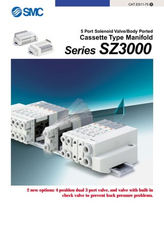
1. 5 Port Solenoid Valve/Body Ported
Cassette Type Manifold
Series SZ3000
CAT.ES11-75 B
2 new options: 4 position dual 3 port valve, and valve with built-in
check valve to prevent back pressure problems.
2. The connector entry
direction can be
changed from top to
side with a simple
operation.
High reliability and long life
of 50 million cycles or more
High reliability and long life have been achieved with
guide ring construction which prevents eccentricity
of the main valve, and a return piston with increased
return force.
(Single and double solenoid types)
High speed response of 10ms
SZ3000 single, 0.5MPa, 24VDC,
without surge voltage suppressor
Low power consumption and a fast response time of
10ms are obtained with a unique pilot valve
construction.
Low power consumption: 0.6W
(current value: 25mA at 24VDC)
Low power consumption enables direct operation by a
PLC. Cost savings are realized through the use of a
smaller power supply and the elimination of relay cards.
The plug-in cassette system
makes valve replacement easy.
A plug-in manifold has been created with a height of 43.5mm (including DIN rail).
Valve replacement can be performed easily.
Moreover, since spare terminals for wiring (receptacle housings) are contained inside the manifold,
terminal changes (additions) can be performed quickly and easily.
(The number of additional stations is limited by the manifold specifications. Refer to page 14 for details.)
Valves equipped with
switches
Adjustment and maintenance of equipment can be
performed with greater safety, since the power to each
valve can be shut off individually with built-in switches.
Features 1
3. Series
Height
Weight
SZ3000
̅31% reduction
̅12% reduction
Series
SZ3000
Replaceable port sizes
C6C4 M5
Port A
Port B
C4/C6 One-touch fitting
C4/C6
One-touch fitting
(elbow type)
M5 port block assembly
∗ Elbow fittings are for C4 and C6 only.
Port PPort R Port R
Port A
Port B
A side coil
A side manual override: Orange A side passage symbol: Orange
B side passage symbol: GreenB side manual override: Green
B side coil
A side spool valve B side spool valve
Model A side B side JIS symbol
SZ3A60
SZ3B60
SZ3C60
N.C.
valve
N.C.
valve
N.O.
valve
N.O.
valve
N.C.
valve
N.O.
valve
SOL.bSOL.a
4(A) 2(B)
5(R)
1(P)
3(R)
SOL.bSOL.a
4(A) 2(B)
5(R)
1(P)
3(R)
4(A) 2(B)
5(R)
1(P)
3(R)SOL.bSOL.a
A B
3-NC
3-NC
NewNew NewNew
4 position dual 3 port valve
• Two 3 port valves are contained in one valve body.
• The A and B ports can be individually controlled.
• [N.C./N.C.], [N.O./N.O.] and [N.C./N.O.] combinations are
available.
• Mixed mounting with 5 port valves is also possible.
• Labels matched to the colors of the manual overrides
are affixed to indicate the "A" and "B" side functions.
Valve with back pressure
check valve
• Prevents malfunction caused by exhaust from other valves.
• Effective for driving single acting cylinders and air operated
valves, or when using exhaust center valves.
• Prevents back pressure individually on "A" and "B" sides of a 4
position dual 3 port valve.
Easy attaching/detaching
of tubes
The interval between ports A and B is a wide 20.5mm,
allowing easy changes of fittings and tubing.
Outstanding seal performance
The new rubber seals offer improved durability and performance.
Valve failures due to line contaminants have been greatly reduced.
(Ozone resistant seals available by special order.)
Common exhaust
This feature provides for a cleaner operating environment by
exhausting the pilot air through the main valve body rather than
directly to the atmosphere.
(Compared with SX3000-45 with DIN rail
manifold and 5 stations)
Size and weight reduced by
eliminating the manifold base
New design and bright color
tones
The top of the manifold has been flattened and the rounding of
corners has been enlarged for easier handling.
In addition, bright white color tones have been adopted to
compliment modern operating environments.
One-touch fittings can be
changed
∗ External pilot specifications are not available for 4 position
dual 3 port valves.
Series SZ3000
5 Port Solenoid Valve/Body Ported
Cassette Type Manifold
Series SZ3000
Features 2
4. TUV Approved Product
Conforms to standards
necessary to satisfy EC
directives.
When ordering TUV approved products,
add "– Q" at the end of the standard part number.
SZ Q
Enter the standard part number
Example of how to order a valve
SS5Z
TUV approved product
Enter the standard part number
TUV approved product
Example of how to order a manifold
Note) Contact SMC for details, as there are limitations on product models, voltage specifications and electrical entry, etc.
Q
TUV Rheinland
BAUART
GEPRUFT
TYPE
APPROVED
The SZ series has received approval for conformity to standards
related to EMC Directives and DIN VDE 0580, from TUV
Rheinland, an EC Notified Body (EC authorization No. 0197).
Moreover, since the rated voltage for this series is 50VDC or less, it
is not subject to low voltage directives.
Features 3
5. How to Order
• Plug-in manifold with power supply terminals
Connector entry direction
Supply/Exhaust
block mounting position
F: D-Sub connector
(25 pins)
P: Flat cable
(26 pins)
PG: Flat cable
(20 pins)
PH: Flat cable
(10 pins)
SS5Z3 – 60 – – –F U PD 1 05
Connector mounting position
1: Perpendicular connector 2: Lateral connector
U
D
B
∗M
U Side (2 to 10 stations)
D Side (2 to 10 stations)
Both sides (2 to 20 stations)
Special specifications
Options
Pilot specifications
Power supply terminal
specifications
Valve stations
F: D-sub connector
Internal pilot specifications
External pilot specifications
Nil
R
Supply/Exhaust block
fitting specifications
Straight
Elbow fittings (upward)
Elbow fittings (downward)
Nil
L
B
Note
Double wiring specification
Specified layout Note 2)
(up to 21 solenoids possible)
Symbol
02
10
02
20
Specifications
24VDC, positive common
12VDC, positive common
24VDC, negative common
12VDC, negative common
Symbol
P
P12
N
N12
Stations
2 stations
10 stations
2 stations
20 stations
......
P: Flat cable connector (26 pins)
Note
Double wiring specification
Specified layout
(up to 22 solenoids possible)
Double wiring specification
Specified layout
(up to 16 solenoids possible)
Symbol
02
11
02
20
Stations
2 stations
11 stations
2 stations
20 stations
......
PG: Flat cable connector (20 pins) PH: Flat cable connector (10 pins)
Double wiring specification
Specified layout
(up to 8 solenoids possible)
NoteSymbol
02
08
02
16
......
Stations
2 stations
8 stations
2 stations
16 stations
......
NoteSymbol
02
04
02
08
...
...
Stations
2 stations
4 stations
2 stations
8 stations
...
...
Note 1) Double wiring specifications: Single, double and 3 position/4 position solenoid
valves can be used at all of the manifold stations.
Note 2) Specified layout: Indicate the wiring specifications on a manifold specification sheet.
(Please note that in locations where single solenoid wiring is indicated, it will be
impossible to use double or 3 position/4 position valves.)
Connector type
Symbol
D
Mounting position
D side
∗ In the case of special
specifications, indicate separately
on a manifold specification sheet.
Note) A total of up to 3 supply/exhaust
blocks can be mounted. Contact
SMC if 4 or more will be mounted.
Note 1)
When a DIN rail is required
that is longer than the
standard types, specify the
number of stations.
......
......
1
5 Port Solenoid Valve
Series SZ3000Plug-inType
6. • Plug-in manifold [without power supply terminals]
Connector type
Supply/Exhaust
block mounting position
F: D-Sub connector
(25 pins)
P: Flat cable
(26 pins)
PG: Flat cable
(20 pins)
PH: Flat cable
(10 pins)
SS5Z3 – 60 – –F U1 05
Connector entry direction
1: Perpendicular connector 2: Lateral connector
U
D
B
∗M
U Side (2 to 10 stations)
D Side (2 to 10 stations)
Both sides (2 to 20 stations)
Special specifications
Options
Pilot specifications
Valve stations
F: D-sub connector
Internal pilot specifications
External pilot specifications
Nil
R
Note
Double wiring specification
Specified wiring Note 2)
(up to 24 solenoids possible)
Symbol
02
12
13
20
...
...
Stations
2 stations
12 stations
13 stations
20 stations
...
...
P: Flat cable connector (26 pins)
Note
Double wiring specification
Specified wiring
(up to 25 solenoids possible)
Double wiring specification
Specified wiring
(up to 19 solenoids possible)
Symbol
02
12
13
20
...
Stations
2 stations
12 stations
13 stations
20 stations
...
......
PG: Flat cable connector (20 pins) PH: Flat cable connector (10 pins)
Double wiring specification
Specified wiring
(up to 9 solenoids possible)
NoteSymbol
02
09
10
19
...
...
Stations
2 stations
9 stations
10 stations
19 stations
...
...
NoteSymbol
02
04
05
09
...
...
Stations
2 stations
4 stations
5 stations
9 stations
...
...
Note 1) Double wiring specifications: Single, double and 3 position/4 position solenoid
valves can be used at all of the manifold stations.
Note 2) Specified layout: Indicate the wiring specifications on a manifold specification sheet.
(Please note that in locations where single solenoid wiring is indicated, it will be
impossible to use double or 3 position/4 position valves.)
D
Connector mounting position
Symbol
D
Mounting position
D side
∗ In the case of special specifications,
indicate separately on a manifold
specification sheet.
Note) A total of up to 3 supply/exhaust
blocks can be mounted. Contact
SMC if 4 or more will be mounted.
How to Order
Supply/Exhaust block
fitting specifications
Straight
Elbow fittings (upward)
Elbow fittings (downward)
Nil
L
B
Note 1)
When a DIN rail is required that
is longer than the standard
types, specify the number of
stations.
Series SZ3000
2
7. How to Order
• How to order solenoid valves For plug-in (common for both with and without power supply terminals)
Nil: Non-locking push type
Nil: Without switch
J: With switch
D: Slotted locking type
Screw driver operated
SZ3 – –51 C6LOZ60
Type of actuation
1
2
3
4
5
A
C
2 position single solenoid
2 position double solenoid
3 position closed center
3 position exhaust center
3 position pressure center
4 position dual 3 port valve: N.C./N.C.
4 position dual 3 port valve: N.O./N.O.
4 position dual 3 port valve: N.C./N.O.
Rated voltage
5
6
24VDC
12VDC
Pilot specifications
Internal pilot
External pilot
Nil
R
Common specifications
Switch specifications
Manual override
Pos. common
Neg. common
Nil
N
A, B port size
C4: ø4 One-touch fitting
C6: ø6 One-touch fitting
M5: M5 x 0.5
Elbow fitting assembly (upward)
L4: ø4 elbow fitting assembly
L6: ø6 elbow fitting assembly
Elbow fitting assembly (downward)
B4: ø4 elbow fitting assembly
B6: ø6 elbow fitting assembly
• When using on a
manifold with power
supply terminals, be
sure to match with
the manifold's voltage
specifications.
SM
C
OF
F
ON
• When using on a manifold
with power supply termi-
nals, be sure to match with
the manifold's common
specifications.
Back pressure
check valve
None
Built-in
Nil
K
• The built-in back pressure
check valve type has an
effective area approximately
20% smaller.
• The 3 position closed center
and 3 position pressure center
are not available with back
pressure check valve.
• The 4 position dual 3 port
valve is not available with
external pilot specifications.
B
(A)
4
(B)
2
5
(EA)
1
(P)
3
(EB)
(A)
4
(B)
2
5
(EA)
1
(P)
3
(EB)
(A)
4
(B)
2
5
(EA)
1
(P)
3
(EB)
(A)
4
(B)
2
5
(EA)
1
(P)
3
(EB)
(A)
4
(A)
4
(A)
4
(A)
4
(B)
2
(B)
2
(B)
2
(B)
2
5
(EA)
1
(P)
3
(EB)
5
(R)
5
(R)
5
(R)
1
(P)
1
(P)
1
(P)
SOL.bSOL.a
3
(R)
3
(R)
3
(R)
SOL.bSOL.a
SOL.bSOL.a
A
4
B
2
A
4
B
2
A
4
B
2
A
4
B
2
∗ Refer to page 48 regarding
switch operation.
3
Cassette Type Manifold Series SZ3000
8. Manifold Specifications
A, B port piping
specifications
Port size
Applicable connector
Internal wiring +COM, –COM
Valve effective Note 2)
area mm²
(Cv factor)
P→A/B
A/B→R
P→A/B
A/B→R
D-sub connector
Complies with
MIL-C-24308
JIS-X-5101
Flat cable connector
Socket: 26 pin MIL type
with strain relief
Complies with
MIL-C-83503
Flat cable connector
Socket: 20 pin MIL type
with strain relief
Complies with
MIL-C-83503
Flat cable connector
Socket: 10 pin MIL type
with strain relief
Complies with
MIL-C-83503
D-sub connector
60F
Flat cable type 60P२
60P
Plug-in type
Common SUP, EXH
Valve
Lateral, Upward, Downward
C8
C4, C6, M5
3.4 (0.19) [3.0 (0.17)]
3.2 (0.18) [3.2 (0.18)]
3.7 (0.21) [3.2 (0.18)]
3.9 (0.22) [3.8 (0.21)]
3.4 (0.19) [3.2 (0.18)]
3.2 (0.18) [3.2 (0.18)]
2 to 20 stations 2 to 16 stations 2 to 8 stations
60PG 60PH
Weight W (g) Note 3)
n1: Stations
n2: Number of supply/exhaust blocks
m : Weight of DIN rail
P→A/B
A/B→R
Location
Direction
C4
C6
M5
P, R ports
A/B ports
Model
Manifold type
P (SUP), R (EXH) system
Valve stations (with power terminal)
How to Order Manifold Assemblies (Example)
Example (SZ3000, positive common with power supply terminals)
Double solenoid (24VDC)
SZ3260-5LOZ-C6 (3 sets)
Single solenoid (24VDC)
SZ3160-5LOZ-C6 (2 sets)
Plug-in manifold with power
supply terminals
SS5Z3-60PD2-05U-P
Supply/Exhaust block (U side mounting)
W = 3.2n1 + 53n2 + m + 126.5
1
2
3
Stations
D
Side
U
Side
Note 1) In cases such as those where many valves are operated simultaneously, use type B (double side supply/exhaust) , applying
pressure to the P ports on both sides and exhausting from the R ports on both sides.
Note 2) • The value is for manifold base mounting (5 stations). 2 position type with individual operation.
Note 3) The weight W is the value for the D-sub connector manifold with power supply terminals only. To obtain the weight with solenoid
valves attached, add the solenoid valve weights given on page 5 for the appropriate number of stations. Refer to page 7 for the
weight of DIN rails.
SS5Z3-60PD2-05U-P....1 set (manifold part number)
SZ3160-5LOZ-C6 ..... 2 sets (single solenoid part number)
SZ3260-5LOZ-C6 ..... 3 sets (double solenoid part number)
The symbol indicates built-in. Put the symbol at the beginning
of the part numbers for solenoid valves, etc., which are to be
attached.
• Valve stations are numbered from station 1 on the D side.
• Indicate the valves to be attached below the manifold part number, in
order starting from station 1 as shown in the drawing. When a layout
becomes complicated, please indicate on a manifold specification
sheet. (Manifold specification sheet on page 37.)
• Values inside [ ] are for 4 position dual 3 port valves. Furthermore, when the "A" and "B" sides of a 4 position dual 3 port valve
are operated simultaneously, the value for the Cv factor will be approximately 35% less than shown in the table above.
• The Cv factor for a valve with back pressure check valve will be approximately 20% less than shown in the table above.
4
Series SZ3000
9. Series
Fluid
2 position single
2 position double
3 position
4 position dual 3 port valve
2 position single
2 position double
3 position
2 position single, double
4 position dual 3 port valve
3 position
Internal pilot
operating
pressure range
MPa
External pilot
operating
pressure range
MPa
Pilot
pressure
range
Operating pressure range
Air
0.15 to 0.7
0.1 to 0.7
0.2 to 0.7
0.15 to 0.7
-100kPa to 0.7
0.25 to 0.7
0.25 to 0.7
0.25 to 0.7
Maximum 50
3
Non-locking push type, Screw driver operated slotted locking type
Main valve/Pilot valve common exhaust type
Not required
Unrestricted
150/30 (8.3 to 2000Hz)
Dust proof
SZ3000
Note) Based on JISB8375-1981 dynamic performance test (with coil temperature of 20°C and at rated voltage).
Note) Only 24VDC and 12VDC are available for plug-in use.
Ambient and fluid temperature °C
Max. operating
frequency Hz
Manual override
Pilot system
Lubrication
Mounting position
Impact/Vibration resistance m/s² Note)
Enclosure
Solenoid Specifications
Electrical entry
Rated coil voltage V Note)
Allowable voltage fluctuation
Power consumption W
Surge voltage suppressor
Indicator light
L type (for plug-in), M type plug connector (M)
24, 12, 6, 5, 3DC
±10% of rated voltage
0.6 (with light: 0.65)
Diode
LED
Weight Table
Response Time
Type of actuation
Response time ms (at 0.5MPa)
2 position single
2 position double
3 position
4 position dual 3 port valve
With surge voltage suppressor
S, Z type
15 or less
13 or less
20 or less
35 or less
12 or less
10 or less
15 or less
30 or less
Without surge voltage
suppressor
Valve model Type of actuation
Port size
A, B
M5 x 0.8
SZ3२60-२-C4
SZ3२60-२-C6
SZ3२60-२-M5
2 position
Weight g
78
84
88
84
74
81
85
81
69
75
79
75
3 position
4 position
4 position
4 position
2 position
3 position
2 position
3 position
Single
Double
Closed center
Exhaust center
Pressure center
Dual 3 port valve
Single
Double
Closed center
Exhaust center
Pressure center
Dual 3 port valve
Single
Double
Closed center
Exhaust center
Pressure center
Dual 3 port valve
C4
ø4 One-touch
fitting
C6
ø6 One-touch
fitting
10
Solenoid Valve Specifications
Note) Impact resistance: No malfunction when tested with a drop tester in the axial direction and at a right angle to the main valve
and armature one time each in both an energized and deenergized condition. (initial value)
Vibration resistance: No malfunction when tested with one sweep of 8.3 to 2000Hz in the axial direction and at a right angle to
the main valve and armature one time each in both an energized and deenergized condition. (initial
value)
5
Cassette Type Manifold Series SZ3000
10. Manifold Options
í SUP blocking disk
í EXH blocking disk
í Indicator stickers for blocking disks
í Silencer with One-touch fitting
í Plugs (white)
Sticker for EXH blocking diskSticker for SUP/EXH blocking disk
By installing a SUP blocking disk in the pressure supply passage of a
manifold valve, it is possible to supply two or more different high and low
pressures to one manifold. (Use in combination with a pilot port blocking
disk.)
í Blanking block assembly
SZ3000-55-1A
These are mounted when later addition of valves is planned, etc.
These stickers are to be put on valves in which SUP and EXH blocking
disks have been installed so that confirmation is possible from the outside.
(3pcs. of each are included.)
By installing an EXH blocking disk in the exhaust passage of a manifold
valve, it is possible to divide the valve's exhaust so that it does not affect
another valve. (Two blocking disk are needed to divide both exhausts.)
SZ3000-155-1A
Sticker for SUP blocking disk Sticker for pilot passage blocking disk
Applicable
fitting size ød
4
6
8
KQ2P-04
KQ2P-06
KQ2P-08
Model A L D
16
18
20.5
32
35
39
6
8
10
Dimensions
øD
L
A
ød
Series
SZ3000
Part no.
SZ3000-114-4A
Series
SZ3000
Part no.
SZ3000-114-4A
Series
for SZ3000 (ø8)
Model
AN203-KM8
Effective sectional area
14mm²
B
26
C
51
A
ø16
A
C
B
A
A
A
A
AB
B
í Pilot port blocking disk
By installing a pilot port blocking disk in the pilot passage of a manifold
valve, it can function as an internal pilot/external pilot mixed manifold.
Series
SZ3000
Part no.
SZ3000-114-2A
This silencer can be mounted on the manifold's port R (exhaust) with a
single touch.
∗ If blocking disks are ordered on manifold specification sheets, etc., at the same time
that manifolds are ordered, stickers will be attached to the valves with blocking disks
installed before shipment.
These are inserted in cylinder ports or SUP/EXH ports which are not being
used.
They can be ordered in multiples of 10 pieces.
Series SZ3000
6
11. ˾ D-sub connector (25 pins)/Cable assembly
˾ Flat cable type/Cable assembly
Cable
length (L)
Assembly no.
AXT100-DS25-015
AXT100-DS25-030
AXT100-DS25-050
1.5m
3m
5m
Note
Cable 25 cores
x24AWG
Item
Conductor
resistance
Ω/km, 20°C
Characteristic
65 or less
Insulation
resistance
MΩkm, 20°C
5 or less
Withstand
voltage
VAC for 1min.
1000
D-sub connector cable assembly
D-sub connector cable assembly
wire colors by terminal number
Sample of connector manufacturers
• HIROSE ELECTRIC COMPANY
• FUJITSU LTD.
• Japan Aviation Electronics Industry, Ltd.
• J.S.T. Mfg. Co., Ltd.
Electrical characteristics
Cable length (L)
1.5m
3m
5m
Connector width (W)
10 pins
AXT100-FC10-1
AXT100-FC10-2
AXT100-FC10-3
17.2
20 pins
AXT100-FC20-1
AXT100-FC20-2
AXT100-FC20-3
30
26 pins
AXT100-FC26-1
AXT100-FC26-2
AXT100-FC26-3
37.5
Flat cable assembly
Sample of connector manufacturers
• HIROSE ELECTRIC COMPANY
• SUMITOMO/3-M LIMITED
• FUJITSU LTD.
• Japan Aviation Electronics Industry, Ltd.
• J.S.T. Mfg. Co., Ltd.
Terminal no.
1
2
3
4
5
6
7
8
9
10
11
12
13
14
15
16
17
18
19
20
21
22
23
24
25
Lead wire color
Black
Brown
Red
Orange
Yellow
Pink
Blue
Purple
Gray
White
White
Yellow
Orange
Yellow
Pink
Blue
Purple
Gray
Orange
Red
Brown
Pink
Gray
Black
White
Dot marking
None
None
None
None
None
None
None
White
Black
Black
Red
Red
Red
Black
Black
White
None
None
Black
White
White
Red
Red
White
None
Terminal no.
Triangle mark position
262
251
Red
˾ DIN rail dimensions/Weight table
No.
L dimension
Weight (g)
0
98
17.6
1
110.5
19.9
2
123
22.1
3
135.5
24.4
4
148
26.6
5
160.5
28.9
6
173
31.1
7
185.5
33.4
8
198
35.6
9
210.5
37.9
No.
L dimension
Weight (g)
10
223
40.1
11
235.5
42.4
12
248
44.6
13
260.5
46.9
14
273
49.1
15
285.5
51.4
16
298
53.6
17
310.5
55.9
18
323
58.1
19
335.5
60.4
No.
L dimension
Weight (g)
20
348
62.6
21
360.5
64.9
22
373
67.1
23
385.5
69.4
24
398
71.6
25
410.5
73.9
26
423
76.1
27
435.5
78.4
28
448
80.6
29
460.5
82.9
VZ1000-11-1-
(7.5)
(25)
(35)
L
8
5.5
Rail mounting hole pitch 12.5
W
L
(15.6)
Refer to the L dimension tables
∗ Enter a number from the DIN rail dimension table below in
the २.
AXT100-FC२-
1
3
~
6
∗ If it is desired to use a commercially available connector, use one conforming to
MIL-C-83503 with strain relief.
Note) The minimum in-
side bending ra-
dius for the D-sub
connector cable
is 20mm.
∗ If it is desired to use a commercially available cable,
use a 25 pin female type connector conforming to
MIL-C24308.
AXT100-DS25-
015
030
050
Vinyl multicore cable
0.3mm² x 25C
2-M2.6 x 0.45Socket side
Terminal no.
Approx.ø10
47.04
55
16
44
8
L
13…………1
25…………14
SMC
Manifold Options
7
Cassette Type Manifold Series SZ3000
12. Manifold Electrical Wiring
• Without power supply terminals • With power supply terminals
60F D-sub connector type (25 pins)
• The maximum number of stations that can be accommodated is 20 manifold stations, with up to 21 solenoids.
Positive common Negative common
• Without power supply terminals • With power supply terminals
60P Flat cable type (26 pins)
• The maximum number of stations that can be accommodated is 20 manifold stations, with up to 22 solenoids.
Positive common Negative common
13
12 25
Common
Station 12
Station 11
SOL.B
SOL.A
SOL.B
SOL.A
Station 2
Station 1
SOL.B
SOL.A
SOL.B
SOL.A
24
11
2
Light/Surge
voltage
suppressor
13
12 25
24
11 23
10
2
1
14
Pos. pin (common)
Neg. pin
Pos. pin (common)
Neg. pin
Station 10
Station 2
Station 1
Power supply terminals
Power supply terminals
SOL.B
SOL.A
SOL.B
SOL.A
SOL.B
SOL.A
13
12 25
24
11 23
10
2
1
14
1515
Pos. pin
Neg. pin (common)
Station 10
Station 2
Station 1
Power supply terminals
SOL.B
SOL.A
SOL.B
SOL.A
SOL.B
SOL.A
15
14
1
24
26
23
25
Common
Station 12
Station 11
SOL.B
SOL.A
SOL.B
SOL.A
Station 2
Station 1
SOL.B
SOL.A
SOL.B
SOL.A
21
22
2
3
4
1
24
26
23
25
Station 11
SOL.B
SOL.A
Station 2
Station 1
SOL.B
SOL.A
SOL.B
SOL.A
Triangle mark
21
22
2
3
4
1
Pos. pin
Neg. pin (common)
Power supply terminals
24
26
23
25
Station 11
SOL.B
SOL.A
Station 2
Station 1
SOL.B
SOL.A
SOL.B
SOL.A
21
22
2
3
4
1
Triangle mark Triangle mark
+– +–
+–+–
• The common polarity should be the same as the
common specifications of the valve to be used.
• The maximum number of stations that can be
accommodated is 20 manifold stations, with up to 24
solenoids.
• The common polarity should be the same as the
common specifications of the valve to be used.
• The maximum number of stations that can be
accommodated is 20 manifold stations, with up to 25
solenoids.
Light/Surge
voltage
suppressor
Light/Surge
voltage
suppressor
Light/Surge
voltage
suppressor
Light/Surge
voltage
suppressor
Light/Surge
voltage
suppressor
Light/Surge
voltage
suppressor
Light/Surge
voltage
suppressor
Light/Surge
voltage
suppressor
Light/Surge
voltage
suppressor
Light/Surge
voltage
suppressor
Light/Surge
voltage
suppressor
• The circuits above are for the double wiring specification with up to 10 or 12 stations. Connect to SOL.A in the case of a single solenoid. Moreover, when wiring instructions are
given on a manifold specification sheet, the "A" signal for single and the "A, B" signals for double should be wired in order 1, 14, 2, 15......etc., without skipping or leaving any
connectors remaining.
• Stations are counted starting with station 1 on the D side.
Light/Surge
voltage
suppressor
Light/Surge
voltage
suppressor
Light/Surge
voltage
suppressor
Light/Surge
voltage
suppressor
Light/Surge
voltage
suppressor
Light/Surge
voltage
suppressor
Light/Surge
voltage
suppressor
Light/Surge
voltage
suppressor
Light/Surge
voltage
suppressor
Light/Surge
voltage
suppressor
Light/Surge
voltage
suppressor
Light/Surge
voltage
suppressor
• The circuits above are for the double wiring specification with up to 11 or 12 stations. Connect to SOL.A in the case of a single solenoid. Moreover, when wiring instructions are
given on a manifold specification sheet, the "A" signal for single and the "A, B" signals for double should be wired in order 1, 2, 3, 4......etc., without skipping or leaving any
connectors remaining.
• Stations are counted starting with station 1 on the D side.
• Since terminal numbers are not indicated on the flat cable, use the triangle mark as a reference when wiring.
Series SZ3000
8
13. Manifold Electrical Wiring
• Without power supply terminals • With power supply terminals
60PG Flat cable type (20 pins)
• The maximum number of stations that can be accommodated is 16 manifold stations, with up to 16 solenoids.
Positive common Negative common
• Without power supply terminals • With power supply terminals
60PH Flat cable type (10 pins)
• The maximum number of stations that can be accommodated is 8 manifold stations, with up to 8 solenoids.
Positive common Negative common
Pos. pin (common)
Neg. pin
Power supply terminals
18
20
17
19
Common
Station 9
Station 8
SOL.B
SOL.A
SOL.B
SOL.A
Station 2
Station 1
SOL.B
SOL.A
SOL.B
SOL.A
15
16
2
3
4
1
10
9
Common
Station 4
SOL.B
SOL.A
Station 2
Station 1
SOL.B
SOL.A
SOL.B
SOL.A
7
8
2
3
4
1
18
20
17
19
Station 8
SOL.B
SOL.A
Station 2
Station 1
SOL.B
SOL.A
SOL.B
SOL.A
Triangle mark
15
16
2
3
4
1
Pos. pin
Neg. pin (common)
Pos. pin
Neg. pin (common)
Pos. pin (common)
Neg. pin
Power supply terminals
Power supply terminals Power supply terminals
18
20
17
19
Station 8
SOL.B
SOL.A
Station 2
Station 1
SOL.B
SOL.A
SOL.B
SOL.A
15
16
2
3
4
1
Triangle mark
Triangle mark
Triangle mark
10
9
Station 4
SOL.B
SOL.A
Station 2
Station 1
SOL.B
SOL.A
SOL.B
SOL.A
7
8
2
3
4
1
Triangle mark
10
9
Station 4
SOL.B
SOL.A
Station 2
Station 1
SOL.B
SOL.A
SOL.B
SOL.A
7
8
2
3
4
1
Triangle mark
+– +–
+– +–
• The common polarity should be the same as the
common specifications of the valve to be used.
• The maximum number of stations that can be
accommodated is 19 manifold stations, with up to 19
solenoids.
• The common polarity should be the same as the
common specifications of the valve to be used.
• The maximum number of stations that can be
accommodated is 9 manifold stations, with up to 9
solenoids.
• The circuits above are for the double wiring specification with up to 8 or 9 stations. Connect to SOL.A in the case of a single solenoid. Moreover, when wiring instructions are
given on a manifold specification sheet, the "A" signal for single and the "A, B" signals for double should be wired in order 1, 2, 3, 4......etc., without skipping or leaving any
connectors remaining.
• Stations are counted starting with station 1 on the D side.
• Since terminal numbers are not indicated on the flat cable, use the triangle mark as a reference when wiring.
Light/Surge
voltage
suppressor
Light/Surge
voltage
suppressor
Light/Surge
voltage
suppressor
Light/Surge
voltage
suppressor
Light/Surge
voltage
suppressor
Light/Surge
voltage
suppressor
Light/Surge
voltage
suppressor
Light/Surge
voltage
suppressor
Light/Surge
voltage
suppressor
Light/Surge
voltage
suppressor
Light/Surge
voltage
suppressor
Light/Surge
voltage
suppressor
Light/Surge
voltage
suppressor
Light/Surge
voltage
suppressor
Light/Surge
voltage
suppressor
Light/Surge
voltage
suppressor
Light/Surge
voltage
suppressor
Light/Surge
voltage
suppressor
Light/Surge
voltage
suppressor
Light/Surge
voltage
suppressor
Light/Surge
voltage
suppressor
Light/Surge
voltage
suppressor
Light/Surge
voltage
suppressor
Light/Surge
voltage
suppressor
• The circuits above are for the double wiring specification with up to 4 stations. Connect to SOL.A in the case of a single solenoid. Moreover, when wiring instructions are given on
a manifold specification sheet, the "A" signal for single and the "A, B" signals for double should be wired in order 1, 2, 3, 4......etc., without skipping or leaving any connectors
remaining.
• Stations are counted starting with station 1 on the D side.
• Since terminal numbers are not indicated on the flat cable, use the triangle mark as a reference when wiring.
9
Cassette Type Manifold Series SZ3000
14. 1. Wiring example when using manifold power supply terminals
2. Wiring example when not using manifold power supply terminals
(power is supplied to the control side or along the wiring, etc.)
Wiring of Plug-in Type Manifold with Power Supply Terminals (Examples)
Caution
SZ manifold internal wiring
(flat cable, positive common specifications) Control side (PLC, etc.)
(NPN open collector output)
20
18
6
4
1
2
3
4
COM
19 Neg. pin
Power supply
terminals
Power supply
Solenoid valve
PLC
Manifold valve
DC power supply
(SS5Z3-60PGD1-05U-२२)
17
5
3
1
2
Cable assembly
AXT100-FC20- , etc.
Triangle mark
+–
+–
SZ manifold internal wiring
(flat cable, positive common specifications)
Control side (PLC, etc.)
(NPN open collector output)
20
18
6
4
1
2
3
4
COM19
Pos. pin
Power supply
terminals
Power supply
Solenoid valve
17
5
3
1
2
Cable assembly
Triangle mark
AXT100-FC20- , etc.+–
+ –
PLC
Manifold valve
DC power supply
(SS5Z3-60PGD1-05U-२२)
• When connecting to a PLC (Programmable Logic Controller), etc., wiring such as the
signal lines and COM position will differ with each manufacturer. Connections should be
made after thoroughly reviewing the electrical circuits of both units in their catalogs or
other materials. If connections are made incorrectly, failure may occur not only in the
manifolds and valves but also in the PLC (control side) and power supply.
• Since the power supply to drive valves with power supply terminals can be supplied from either the control side or the manifold side, these wiring
examples should be used for reference when wiring is performed.
Series SZ3000
10
15. JIS symbol
2 position single
2 position single with
back pressure check valve
2 position double with
back pressure check valve
3 position exhaust center with
back pressure check valve
2 position double
JIS symbol
2 position double
JIS symbol
3 position closed center
3 position exhaust center
3 position pressure center
2 position single
3 position closed center/exhaust center/pressure center
2 position single with back pressure check valve
Construction
Refer to One-touch fitting part number information on page 51.
SX3000-115-2
Part no.
One-touch fitting
Clip
Description
9
10
No
Parts list
Replacement parts
(A)
4
(B)
2
5
(EA)
1
(P)
3
(EB)
(A)
4
(B)
2
5
(EA)
1
(P)
3
(EB)
(A)
4
(B)
2
5
(EA)
1
(P)
3
(EB)
(A)
4
(B)
2
5
(EA)
1
(P)
3
(EB)
(A)
4
(B)
2
5
(EA)
1
(P)
3
(EB)
(A)
4
(B)
2
5
(EA)
1
(P)
3
(EB)
(A)
4
(B)
2
5
(EA)
1
(P)
3
(EB)
(A)
4
(B)
2
5
(EA)
1
(P)
3
(EB)
Body
Adapter plate
Pilot body
Molded coil
Body cover
Spool valve assembly
Port block
Bottom cover assembly
Zinc die cast
PBT
PA
–
PA
Aluminum/NBR
PA
–
Material Note
–
White
White
Gray
White
–
White
White
DescriptionNo.
1
2
3
4
5
6
7
8
4(A)
2 (B)
5 (EA)
1 (P)
3 (EB)
4 (A)
2 (B)
5 (EA)
1 (P)
3 (EB)
4 (A)
2 (B)
4 (A)
2 (B)
5 (EA)
1 (P)
3 (EB)
5 (EA)
1 (P)
3 (EB)
11
Cassette Type Manifold Series SZ3000
16. JIS symbol
4 position dual 3 port valve
SZ3A60 [N.C. valve x 2pcs.]
SZ3A60K/With back pressure check valve
SZ3A60 [N.C. valve x 2pcs.]
SZ3B60 [N.C. valve x 2pcs.]
SZ3B60K/With back pressure check valve
SZ3B60 [N.O.valve x 2pcs.]
SZ3C60 [N.C. valve, N.O. valve 1pc. each]
SZ3C60K/With back pressure check valve
SZ3C60 [N.C valve, N.O. valve 1pc. each]
SZ3A60K/With back pressure check valve
Refer to One-touch fitting part number information on page 51.
SX3000-115-2
Part no.
One-touch fitting
Clip
Description
10
11
No.
Parts list
Replacement parts
4 (A) 2 (B)
4 (A) 2 (B)
5 (R)
SOL.a
5 (R)
SOL.a
SOL.b
1 (P)
3 (R)
SOL.b
1 (P)
3 (R)
4 (A) 2 (B)
4 (A) 2 (B)
5 (R)
SOL.a
5 (R)
SOL.a
SOL.b
1 (P)
3 (R)
SOL.b
1 (P)
3 (R)
4 (A) 2 (B)
4 (A) 2 (B)
5 (R)
SOL.a
5 (R)
SOL.a
SOL.b
1 (P)
3 (R)
SOL.b
1 (P)
3 (R)
Spool valve assembly
Spool valve assembly
Body
Adapter plate
Pilot body
Molded coil
Body cover
Port block
Bottom cover assembly
PA/NBR
PA/NBR
Zinc die cast
PBT
PA
—
PA
PA
—
Material Note
For N.C. (normally closed)
For N.O. (normally open)
—
White
White
Gray
White
White
White
DescriptionNo.
1
2
3
4
5
6
7
8
9
5 (R)
1 (P)
3 (R)
5 (R)
1 (P)
3 (R)
5 (R)
1 (P)
3 (R)
5 (EA)
1 (P)
3 (EB)
Series SZ3000
12
17. 60P manifold (plug-in, flat cable type)
Manifold Exploded View
1
2
3
4
5
6
7
Supply/Exhaust block assembly
End block assembly
Housing holder
Bushing assembly
Bushing assembly
DIN rail
Connector block assembly
Part no. Note
Refer to page 7
Refer to the connector block assembly part no. table below.
C6: with ø6 One-touch fitting, C8: with ø8 One-touch fitting
Description
Connector specifications
Part no.
Note
∗ 1: Perpendicular connector
∗ 2: Lateral connector
P: Positive common
N: Negative common
Without power supply terminals With power supply terminals
For D-sub connector
For flat cable 26 pins
For flat cable 20 pins
For flat cable 10 pins
No.
Parts list
Connector block assembly part numbers
SZ3000-50-1A-
SZ3000-53-1A
SX3000-113-1
SZ3000-114-3A
SZ3000-114-1A
VZ1000-11-1-२
SZ3000-40-२२
SZ3000-40-1A-२२D
SZ3000-40-3A-२२D
SZ3000-40-5A-२२D
SZ3000-40-7A-२२D
Note 1)
1
2
1
2
1
2
1
2
C6
C8
SZ3000-40-2A-२२D -
SZ3000-40-4A-२२D -
SZ3000-40-6A-२२D -
SZ3000-40-8A-२२D -
1
2
P
N
1
2
P
N
1
2
P
N
1
2
P
N
Mounting
position
D side
D side
D side
D side
A connector block assembly can be shipped as an assembly only in the case
of double wiring. Since the possible number of stations differs depending on
the connector type, refer to the valve station section on catalog page 2 and
enter the number of stations in the २२ section of the assembly part number.
Contact SMC if a connector block assembly is required having a wiring
specification other than double wiring.
U side
D side
Note)
The assembly part numbers
with power supply terminals
are 24VDC specifications.
If 12VDC specifications are
required, enter "12" at the
end of the assembly part
number.
13
Cassette Type Manifold Series SZ3000
18. 4. Mount the valve on the DIN rail.
Caution In addition to solenoid valves, housing holders (SX3000-113-1) are necessary for expansion of manifold stations.
Plug-in Manifold Station Expansion
• Double wiring specification manifolds which do not have the maximum number of stations, contain spare receptacle housings for expansion in
the housing holder of the last station, or inside the supply/exhaust block assembly (for a maximum of 2 stations). When expanding stations,
perform the disassembly and assembly of the manifold while referring to the expansion method shown below.
Caution
End block
Supply/exhaust block
Contains receptacle housings
for expansion
Receptacle housing
Housing holder (SX3000-113-1)
U Side
D Side
1. Loosen the DIN rail holding screw of the end block on
the U side.
2. Separate the end block and supply/exhaust block.
3. Take out the receptacle housing for expansion which is
inside the supply/exhaust block, attach it to the newly
added housing holder, and attach to the manifold.
(Numbers are displayed on the side of the receptacle
housings, and they should be used in order from the
lowest number.)
5. While pressing the manifold together from both sides,
refasten the side U end block's DIN rail holding screw.
Caution (tightening torque: 1.4Nm)
1. Be sure to shut off the power and air supplies before disassembling. Since air
may remain inside actuators, piping and manifolds, confirm that the air is
completely exhausted before beginning work.
2. When disassembly and assembly are performed, air leakage may result if
connections between blocks and tightening of the end block's holding screw,
is inadequate. Before supplying air, confirm that there are no gaps, etc.
between blocks, and that manifold blocks are securely fastened to the DIN
rail. Then, supply air and confirm that there is no air leakage before operating.
3. Note that for manifolds specified with other than double wiring, spare
receptacle housings for expansion are not included unless indicated at the
time of order.
2. Align
connectors
3. Attach to rail by pushing on
coil area
1. Hook on rail
Series SZ3000
14
19. 1
2
OFF
ON
OFF
ON
[With external pilot]
Scale: 37%
Dimensions/SZ3000: Plug-in
StationsSS5Z3-60FD U--
L1
L2
L3
L4
L
n 2
110.5
100
81
15
5
148
137.5
112.5
18
6
148
137.5
123
12.5
7
160.5
150
133.5
13.5
8
173
162.5
144
14.5
9
185.5
175
154.5
15.5
10
198
187.5
165
16.5
4
135.5
125
102
17
3
123
112.5
91.5
16
Internal pilot manifold L: Dimensions n: Stations (n1 + n2)
L1
L2
L3
L4
L
n 2
123
112.5
91.5
16
5
148
137.5
123
12.5
6
160.5
150
133.5
13.5
7
173
162.5
144
14.5
8
185.5
175
154.5
15.5
9
198
187.5
165
16.5
10
210.5
200
175.5
17.5
4
148
137.5
112.5
18
3
135.5
125
102
17
External pilot manifold L: Dimensions n: Stations (n1 + n2)
24
16.217.8
6
7.5
37.5
34
13.3
2-One-touch fitting
(P, R ports)
Applicable tube O.D.: ø8
2-One-touch fitting
(X, PE ports)
Applicable tube O.D.: ø6
2n2-One-touch fitting
(A, B ports)
Applicable tube O.D.: ø4
ø6
2n1-M5 x 0.8
(A, B ports)
24
34
17
36.7
(3.2)101.23.5
(Withswitchmounted)
43.5
49.4
(34.5)
5.5
35
6.5
36.358.2
9
8
(Rail mounting hole pitch 12.5)
22.7
(5.9)
5
3.1
18
28.8
16.2
13.3
(Pitch)
P= 10.5
DIN rail
DIN rail holding screw
Switch
(when equipped with switch)
Power supply terminals
(M3 terminal screws)
L3
L2
L1
(L4)
Manual override
(The voltage indication
marking is for 24VDC.)
A: Orange
B: Green
Light/Surge voltage suppressor
Side A: Orange
Side B: Green
(Station n) ........ (Station 1)
Connector case
attachment lever (both sides)
Lateral connector entry
Applicable connector: D-SUB equivalent{ }JIS-X-5101
MIL-C-24308
A4A4A4A4A4P1
B2B2B2B2B2
R3
A4A4A4A4P1
B2
A4
B2B2B2B2
R3
24VDC
+COM
In case of locking type,
turn after pushing in.
X
PE
( )
(7.5)
(DINraildimension)
Note ) Refer to page 19 for manifold dimensions with elbow fitting.
Terminal no.1
15
Cassette Type Manifold Series SZ3000
21. A4A4A4A4
B2B2B2B2
A4
B2
P1
R3
A4A4A4
B2
A4
B2
A4
B2B2B2
P1
R3
24VDC
+COM
OFF
ON
OFF
ON
Scale: 37%
[With external pilot]
24
16.2
34
6
7.5
37.5
34
13.3
2-One-touch fitting
(P, R ports)
Applicable tube O.D.: ø8
2-One-touch fitting
(X, PE ports)
Applicable tube O.D.: ø6
2n1-M5 x 0.8
(A, B ports)
24
34
17
36.7
(3.2)101.2
43.5
62.4
(33.1)
(7.5)
(DINraildimension)
5.5
35
6.5
36.358.2
7.6
8
(Rail mounting hole pitch 12.5)
Triangle mark location
(for lateral connector entry)
22.7
(18.9)
5
3.1
18
28.8
16.2
13.3
(Pitch)
P=10.5
DIN rail
DIN rail holding screw
L3
L2
L1
(L4)
Manual override
Power supply terminals
(M3 terminal screws)
(The voltage indication
marking is for 24VDC. )A: Orange
B: Green
(Station n) ........ (Station 1)
Triangle mark location
Triangle mark
Triangle mark location
Connector case
attachment lever (both sides)
Lateral connector entry
Applicable connector:
26 pin MIL type with strain relief
(conforms to MIL-C-83503)
Dimensions/SZ3000: Plug-in
L1
L2
L3
L4
L
n 2
110.5
100
81
15
5
148
137.5
112.5
18
6
148
137.5
123
12.5
7
160.5
150
133.5
13.5
8
173
162.5
144
14.5
9
185.5
175
154.5
15.5
10
198
187.5
165
16.5
4
135.5
125
102
17
3
123
112.5
91.5
16
Internal pilot manifold L: Dimensions n: Stations (n1 + n2)
L1
L2
L3
L4
L
n 2
123
112.5
91.5
16
5
148
137.5
123
12.5
6
160.5
150
133.5
13.5
7
173
162.5
144
14.5
8
185.5
175
154.5
15.5
9
198
187.5
165
16.5
10
210.5
200
175.5
17.5
4
148
137.5
112.5
18
3
135.5
125
102
17
External pilot manifold L: Dimensions n: Stations (n1 + n2)
StationsSS5Z3-60PD (26 pins)U--1
2
Light/Surge voltage suppressor
Side A: Orange
Side B: Green
Applicable connector:
20 pin MIL type with strain relief
(conforms to MIL-C-83503)
Applicable connector:
10 pin MIL type with strain relief
(conforms to MIL-C-83503)
60PG (20 pins) 60PH (10 pins)
2n2-One-touch fitting
(A, B ports)
Applicable tube O.D.: ø4
ø6
3.5
(Whenswitchismounted)
Switch
(when equipped with switch)
24VDC
+COM
24VDC
+COM
X
PE
In case of locking type,
turn after pushing in.
Note 1) Types 60PG and 60PH differ only in their connectors, and the L1
through L4 dimensions are the same as type 60P.
Note 2) Refer to page 19 for manifold dimensions with elbow fitting.
( )
17
Cassette Type Manifold Series SZ3000
22. Switch
(when equipped with switch)
A4A4A4A4
B2B2B2B2
A4
B2
P1
R3
P1
R3
A4A4A44
B2
A4
B2
A4
B2B2B22
P1
R3
P1
R3
24VDC
+COM
24VDC
+COM
24VDC
+COM
Scale: 37%
[With external pilot]
24
16.2
34
6
7.5 37.5
34
13.3
4-One-touch fitting
(P, R ports)
Applicable tube O.D.: ø8
2-One-touch fitting
(X, PE ports)
Applicable tube O.D.: ø6
2n-One-touch fitting
(A, B ports)
Applicable tube O.D.: ø4
ø6
24
36.7
16.2
34
(3.2)101.2
43.5
62.4
(33.1)
(7.5)
(DINraildimension)
5.5
35
6.5
36.3
3.1
58.2
7.6
8
(Rail mounting hole pitch 12.5)
Triangle mark location
(for lateral connector entry)
22.7
(18.9)
5
18
28.8
17
13.3
(Pitch)
P= 10.5
L3
L2
L1
(L4)
Manual override
A: Orange
B: Green
(Station n) ......... (Station 1)
Triangle mark location
Triangle mark location
Triangle mark
Triangle mark
location
Connector case
attachment lever (both sides)
60PG (20 pins) 60PH (10 pins)
L1
L2
L3
L4
L
n 2
135.5
125
107.5
14
3
148
137.5
118
15
4
160.5
150
128.5
16
5
173
162.5
139
17
6
173
162.5
149.5
12
7
185.5
175
160
13
8
198
187.5
170.5
14
9
210.5
200
181
15
10
223
212.5
191.5
16
11
235.5
225
202
17
12
248
237.5
212.5
18
13
248
237.5
223
12.5
14
260.5
250
233.5
13.5
15
273
262.5
244
14.5
16
285.5
275
254.5
15.5
17
298
287.5
265
16.5
18
310.5
300
275.5
17.5
19
310.5
300
286
12.5
20
323
312.5
296.5
13.5
Dimensions/SZ3000: Plug-in
StationsSS5Z3-60PD (26 pins)B--1
2
External pilot manifold L: Dimensions n: Stations (n1 + n2)
L1
L2
L3
L4
L
n 2
123
112.5
97
13
3
135.5
125
107.5
14
4
148
137.5
118
15
5
160.5
150
128.5
16
6
173
162.5
139
17
7
173
162.5
149.5
12
8
185.5
175
160
13
9
198
187.5
170.5
14
10
210.5
200
181
15
11
223
212.5
191.5
16
12
235.5
225
202
17
13
248
237.5
212.5
18
14
248
237.5
223
12.5
15
260.5
250
233.5
13.5
16
273
262.5
244
14.5
17
285.5
275
254.5
15.5
18
298
287.5
265
16.5
19
310.5
300
275.5
17.5
20
310.5
300
286
12.3
Internal pilot manifold L: Dimensions n: Stations (n1 + n2)
DIN rail
Applicable connector:
26 pin MIL type with strain relief
(conforms to MIL-C-83503)
DIN rail holding screw
Lateral connector entry
Power supply terminals (M3 terminal screws)
The voltage indication
marking is for 24VDC.
Light/Surge voltage suppressor
Side A: Orange
Side B: Green
Applicable connector:
20 pin MIL type with strain relief
(conforms to MIL-C-83503)
Applicable connector:
10 pin MIL type with strain relief
(conforms to MIL-C-83503)
OFF
ON
OFF
ON
2n1-M5 x 0.8
(A, B ports)
3.5
Whenequipped
withSwitch
In case of locking type,
turn after pushing in.
Note 1) Types 60PG and 60PH differ only in their connectors, and the
L1 through L4 dimensions are the same as type 60P.
Note 2) Refer to page 19 for manifold dimensions with elbow fitting.
X
PE
( )
()
( )
Series SZ3000
18
23. Dimensions with Elbow Fitting/SZ3000: Plug-in, D-Sub Connector
StationSS5Z3-60F1D D -- L
B
43.5
10.413.9
10.45.4
(127.9)
36.333.4
25.8
9.8
16.2
34.8
36.7
[Port4(A)]
55.3(3.2)
17
40.3
57.3
34
[Port1(P)]
(7.5)
(DINraildimension)
13.7
(3)
3.2 3.3 (3)2.4
4 (A)
2 (B)
3 (R)
1 (P)
18.1
(3.2)
2-One-touch fitting
[port 1 (P), 3 (R)]
Applicable tube O.D.: ø8m (SMC)
24 13.3 (Pitch)
P= 10.5
A
24VDC
+COM
B
AB
[Valve] [Supply/Exaust block]
Downward (B type)
(Station n) ............ (Station 1)
Port 3 (R)
U side D side
Port 1 (P) Port 4 (A)
Port 2 (B)
(The fitting dimension of the flat cable and non-plug-in types is the same.)
Scale: 37%
19
Cassette Type Manifold Series SZ3000
24. How to Order
• Non-plug-in manifold
Supply/Exhaust block
mounting position
SS5Z3 – 60 – –U05
02
20
D side (2 to 10 stations)
U side (2 to 10 stations)
Both sides (2 to 20 stations)
Special specifications
Options
Pilot specifications
Manifold stations
Internal pilot specifications
External pilot specifications
2 stations
20 stations
Nil
R
Supply/Exhaust block
fitting specifications
Straight
Elbow type (upward)
Elbow type (downward)
Nil
L
B
...
...
∗ In the case of special
specifications, indicate separately
on a manifold specification sheet.
Note) A total of up to 3 supply/exhaust
blocks can be mounted. Contact
SMC if 4 or more will be mounted.
D
U
B
M∗
How to Order Manifold Assemblies (Example)
Example (SZ3000, non-plug-in)
SS5Z3-60-05U ........... 1set (manifold part number)
SZ3160-5M-C6 .......... 2 sets (single solenoid part number)
SZ3260-5M-C6 .......... 3 sets (double solenoid part number)
The symbol indicates built-in. Put the symbol at the beginning of
the part numbers for solenoid valves, etc. which are to be attached.
• The layout of valves starts with station 1 on the D side.
• Indicate the valves to be attached below the product part number, in
order starting from station 1 as shown in the drawing. When a layout
becomes complicated, please indicate on a manifold specification sheet.
(Manifold specification sheet on page 39.)
S
tations...3
2
1
U
side
D
side
Supply/Exhaust block
(U side mounting)
Double solenoid (24VDC)
SZ3260-5M-C6 (3 sets)
Single solenoid (24VDC)
SZ3160-5M-C6 (2 sets)
When a DIN rail is required that is longer than the
standard types, specify the number of stations.
5 Port Solenoid Valve
Series SZ3000Non-Plug-inType
20
25. How to Order
Nil: Non-locking push type
D: Slotted locking type
Screw driver operated
SZ3 – –51 C6M60
Type of actuation
1
2
3
4
5
A
C
2 position single solenoid
2 position double solenoid
3 position closed center
3 position exhaust center
3 position pressure center
4 position dual 3 port valve: N.C./N.C.
4 position dual 3 port valve: N.O./N.O.
4 position dual 3 port valve: N.C./N.O.
Rated voltage
5
6
V
S
R
24VDC
12VDC
6VDC
5VDC
3VDC
Pilot
specifications
Internal pilot
External pilot
Nil
R
Common specifications
Electrical entry
Manual override
Pos. common
Neg. common
Nil
N
A, B port size
C4: ø4 One-touch fitting
C6: ø6 One-touch fitting
M5: M5 x 0.5
Elbow fitting assembly (upward)
L4: ø4 elbow fitting assembly
L6: ø6 elbow fitting assembly
Elbow fitting assembly (downward)
B4: ø4 elbow fitting assembly
B6: ø6 elbow fitting assembly• The symbol is "Nil"
when not equipped with
light/surge voltage
suppressor.
Light/Surge
voltage suppressor
Without light/Surge
voltage suppressor
With light/Surge voltage
suppressor
With surge voltage suppressor
Nil
S
Z
• The 4 position dual 3
port valve is not
available with external
pilot specifications.
B
(A)
4
(B)
2
5
(EA)
1
(P)
3
(EB)
(A)
4
(B)
2
5
(EA)
1
(P)
3
(EB)
(A)
4
(B)
2
5
(EA)
1
(P)
3
(EB)
(A)
4
(B)
2
5
(EA)
1
(P)
3
(EB)
(A)
4
(B)
2
5
(EA)
1
(P)
3
(EB)
SOL.bSOL.a
SOL.bSOL.a
SOL.bSOL.a
B
C
O
M
A
-
+
-
B
C
O
M
A
-
+
-
MN: Without lead wire MO: Without connectorM: With lead wire (length 300mm)
Back pressure
check valve
None
Built-in
Nil
K
A
4
B
2
A
4
B
2
A
4
B
2
A
4
B
2
(A)
4
(B)
2
5
(R)
1
(P)
3
(R)
(A)
4
(B)
2
5
(R)
1
(P)
3
(R)
(A)
4
(B)
2
5
(R)
1
(P)
3
(R)
21
Cassette Type Manifold Series SZ3000
26. Model
A, B port piping
specifications
Port size
Valve
effective
area mm²
(Cv factor)
P→A/B
A/B→R
P→A/B
A/B→R
SS5Z3-60
Non-plug-in type
Common SUP, EXH
Valve
Lateral, Upward, Downward
C8
C4, C6, M5
3.4 (0.19) [3.0 (0.17)]
3.2 (0.18) [3.2 (0.18)]
3.7 (0.21) [3.2 (0.18)]
3.9 (0.22) [ 3.8 (0.21)]
3.4 (0.19) [3.2 (0.18)]
3.2 (0.18) [3.2 (0.18)]
2 to 20 stations
Weight W (g) Note 3)
n: Number of supply/exhaust blocks
m: Weight of DIN rail
P→A/B
A/B→R
Location
Direction
C4
C6
M5
P, EA, EB ports
A/B ports
Manifold type
P (SUP), R (EXH) system
Valve stations
W = 34n + m + 89
Note 2)
Manifold Specifications
Note 1) In cases such as those where many valves are operated simultaneously, use type B (double side supply/exhaust),
applying pressure to the P ports on both sides and exhausting from the R ports on both sides.
Note 2) •The value is for manifold base mounting (5 stations). 2 position type with individual operation.
Note 3) The weight W is the value for the manifold only. To obtain the weight with solenoid valves attached, add the
solenoid valve weights given on page 5 for the appropriate number of stations. Refer to page 7 for the weight of
DIN rails.
• Values inside [ ] are for 4 position dual 3 port valves. Furthermore, when the "A" and "B" sides of a 4 position
dual 3 port valve are operated simultaneously, the value for the Cv factor will be approximately 35% less than
shown in the table above.
• The Cv factor for a valve with back pressure check valve will be approximately 20% less than shown in the table
above.
Series SZ3000
22
27. Type 60 (non-plug-in) manifold
Manifold station expansion Station expansion is possible at any position.
Manifold Exploded View
1. Loosen one DIN rail holding screw on either the U side or D side.
2. Separate the blocks at the location where station expansion is desired.
3. Mount the valve on the DIN rail.
4. While pressing the manifold together from both sides, retighten the DIN rail holding
screw of the end block assembly which was loosened.
1
2
3
4
5
6
Supply/Exhaust block
assembly
End block assembly
End block assembly
Bushing assembly
Bushing assembly
DIN rail
Part no. Note
C6: With ø6 One-touch fitting
C8: With ø8 One-touch fitting
For D side
For U side
Refer to page 7.
DescriptionNo.
SZ3000-50-2A-
SZ3000-53-3A
SZ3000-53-4A
SZ3000-114-3A
SZ3000-114-1A
VZ1000-11-1-२
Caution
(tightening torque: 1.4N⋅m)Caution
DIN rail holding screw
U side
D sideDIN rail holding screw
C6
C8
1. Be sure to shut off the power and air supplies before disassembling. Since air may re-
main inside actuators, piping and manifolds, confirm that the air is completely ex-
hausted before beginning work.
2. When disassembly and assembly are performed, air leakage may result if connections
between blocks and tightening of the end block's holding screw are inadequate. Be-
fore supplying air, confirm that there are no gaps between blocks, and that manifold
blocks are securely fastened to the DIN rail. Then, supply air and confirm that there is
no air leakage before operating.
23
Cassette Type Manifold Series SZ3000
28. A4A4A4
B2B2B2
A4
B2
A4
B2
P1
R3
A4A4X4
B2
A4
B2
A4
B2
A4
B2B2PE2
P1
R3
U Side D Side
[With external pilot]
Scale: 37%
24
16.217.8Approx.300
Leadwirelength
18.7
13.3
2-One-touch fitting
(P, R ports)
Applicable tube O.D.: ø8
2-One-touch fitting
(X, PE ports)
Applicable tube O.D.: ø6
2n-One-touch fitting
(A, B ports)
Applicable tube O.D.: ø4
ø6
24
34
17
36.7
(3.2)113.7
43.5
(7.5)
(DINraildimension)35
5.5
36.343.7
DIN rail
8
1.4
(Rail mounting hole pitch 12.5)
DIN rail holding screw
3.1
18
28.8
16.2
13.3
(Pitch)
P = 10.5
L3
L2
L1
(L4)
Manual override
A: Orange
B: Green
Light/Surge voltage suppressor
Side A: Orange
Side B: Green
(Station n) ......... (Station 1)
Dimensions/SZ3000: Non-plug-in
StationsSS5Z3-60 U-
L1
L2
L3
L4
L
n 2
98
87.5
70
14
5
135.5
125
101.5
17
6
135.5
125
112
12
7
148
137.5
122.5
13
8
160.5
150
133
14
9
173
162.5
143.5
15
10
185.5
175
154
16
4
123
112.5
91
16
3
110.5
100
80.5
15
Internal pilot manifold L: Dimensions n: Stations
L1
L2
L3
L4
L
n 2
110.5
100
80.5
15
5
135.5
125
112
12
6
148
137.5
122.5
13
7
160.5
150
133
14
8
173
162.5
143.5
15
9
185.5
175
154
16
10
198
187.5
164.5
17
4
135.5
125
101.5
17
3
123
112.5
91
16
External pilot manifold L: Dimensions n: Stations
In case of locking type,
turn after pushing in.( )
Note ) Refer to page 19 for manifold dimensions with elbow fitting.
Series SZ3000
24
29. A4A4A4
B2B2B2
A4
B2
A4
B2
P1
R3
A4A4A4
B2
A4
B2
A4
B2B2B2
A4
B2
P1
R3
U Side D Side
[With external pilot]
Scale: 37%
21.3
16.217.8Approx.300
Leadwirelength
18.7
2-One-touch fitting
(P, R ports )
Applicable tube O.D.: ø8
2-One-touch fitting
(X, PE ports)
Applicable tube O.D.: ø6
2n-One-touch fitting
(A, B ports)
Applicable tube O.D.: ø4
ø6
21.3
34
17
36.7
(3.2)113.7
43.5
(7.5)
(DINraildimension)35
5.5
36.343.7
DIN rail
8
(Rail mounting hole pitch 12.5)
DIN rail holding screw
3.1
18
28.8
16.2
13.3
(Pitch)
P = 10.5
L3
L2
L1
(L4)
Manual override
In case of locking type,
turn after pushing in.
A: Orange
B: Green
Light/Surge voltage suppressor
Side A: Orange
Side B: Green
(Station n) ........ (Station 1)
Dimensions/SZ3000: Non-plug-in
StationsSS5Z3-60 D-
L1
L2
L3
L4
L
n 2
98
87.5
70
14
5
135.5
125
101.5
17
6
135.5
125
112
12
7
148
137.5
122.5
13
8
160.5
150
133
14
9
173
162.5
143.5
15
10
185.5
175
154
16
4
123
112.5
91
16
3
110.5
100
80.5
15
Internal pilot manifold L: Dimensions n: Stations
L1
L2
L3
L4
L
n 2
110.5
100
80.5
15
5
135.5
125
112
12
6
148
137.5
122.5
13
7
160.5
150
133
14
8
173
162.5
143.5
15
9
185.5
175
154
16
10
198
187.5
164.5
17
4
135.5
125
101.5
17
3
123
112.5
91
16
External pilot manifold L: Dimensions n: Stations
( )
Note ) Refer to page 19 for manifold dimensions with elbow fitting.
25
Cassette Type Manifold Series SZ3000
32. How to Order
Supply/Exhaust block mounting position
SS5Z3–60S ––D
Symbol
02
08
02
16
U side (2 to 10 stations)
D side (2 to 10 stations)
Both sides (2 to 16 stations)
Special specifications
Q
Options
Pilot specifications
Valve stations
Internal pilot specifications
External pilot specifications
Stations
2 stations
8 stations
2 stations
16 stations
Note
Double wiring specifications
Specified layout
(up to 16 solenoids possible)
Nil
R
D sideD
U
D
B
M∗
……
……Compatible equipment
SI unit mounting position
Q
R1
R2
V
F
H
J1
J2
O
U05
∗ In the case of special specifications,
indicate separately on a manifold
specification sheet.
Note) A total of up to 3 supply/exhaust
blocks can be mounted. Contact
SMC if 4 or more will be mounted.
Note 1) Double wiring specifications:
Single, double and 3 position solenoid valves
can be used at all of the manifold stations.
Note 2) Specified layout:
Indicate the wiring specifications on a manifold
specification sheet. (Note that in locations
where single solenoid wiring is indicated, it will
be impossible to use double, 3 position or 4
position valves.)
Note 3) R2 and J2 are available with up to 8 solenoids.
DeviceNet compatible:
OMRON Corp. CompoBus/D compatible
OMRON Corporation:
CompoBus/S (16 points) compatible
OMRON Corporation:
CompoBus/S (8 points) compatible
Mitsubishi Electric Corp.: CC-Link compatible
NKE Corporation
Simple wiring standard system compatible
NKE Corporation
Simple wiring H system compatible
Sanks Corporation
S-LINK system (16 point output) compatible
Sanks Corporation
S-LINK system (8 point output) compatible
Without SI unit
Supply/Exhaust block
fitting specifications
Straight
Elbow type (upward)
Elbow type (downward)
Nil
L
B
How to Order Manifold Assemblies (Example)
Example (OMRON Corporation compatible serial unit)
SS5Z3-60SRID-05U-C6 .... 1 set (manifold part number)
SZ3160-5LOZ-C6............... 2 sets (single solenoid part number)
SZ3260-5LOZ-C6............... 3 sets (double solenoid part number)
The symbol indicates built-in. Put the symbol at the beginning of the
part numbers for solenoid valves, etc., which are to be installed.
• The valve layout starts with station 1 on the D side.
• Indicate the valves to be installed below the product part number, in order
starting from station 1 as shown in the drawing. When a layout becomes
complicated, please indicate on a manifold specification sheet. (Manifold
specification sheet on page 41.)
S
tations...3
2
1
U
side
D
side
Supply/Exhaust block assembly
(U side mounting)
Double solenoid (24VDC)
SZ3260-5LOZ-C6 (3 sets)
Single solenoid (24VDC)
SZ3160-5LOZ-C6 (2 sets)
Serial unit
(D side mounting)
When a DIN rail is required that
is longer than the standard
types, specify the number of
stations.
• This should be indicated even
without SI unit.
60S२
5 Port Solenoid Valve
Series SZ3000SerialTransmissionType
28
33. A
4
B
2
How to Order
Nil: Non-locking push type
D: Slotted locking type
Screw driver operated
SZ3 – –5LOZ1 C660
Type of actuation
1
2
3
4
5
A
C
2 position single solenoid
2 position double solenoid
3 position closed center
3 position exhaust center
3 position pressure center
4 position dual 3 port valve: N.C./N.C.
4 position dual 3 port valve: N.O./N.O.
4 position dual 3 port valve: N.C./N.O.
Pilot specifications
Internal pilot
External pilot
Nil
R
Switch specifications Manual override
A, B port size
C4: ø4 One-touch fitting
C6: ø6 One-touch fitting
M5: M5 x 0.5
Elbow fitting assembly (upward)
L4: ø4 elbow fitting assembly
L6: ø6 elbow fitting assembly
Elbow fitting assembly (downward)
B4: ø4 elbow fitting assembly
B6: ø6 elbow fitting assembly
• Dual 3 port valves are not
available with external pilot
specifications.
B
(A)
4
(B)
2
5
(EA)
1
(P)
3
(EB)
(A)
4
(B)
2
5
(EA)
1
(P)
3
(EB)
(A)
4
(B)
2
5
(EA)
1
(P)
3
(EB)
(A)
4
(B)
2
5
(EA)
1
(P)
3
(EB)
(A)
4
(B)
2
5
(EA)
1
(P)
3
(EB)
SOL.bSOL.a
SOL.bSOL.a
SOL.bSOL.a
Nil: Without switch
J: With switch
SM
C
OF
F
ON
∗ Refer to page 48 for switch operation.
Back pressure check valve
None
Built-in
Nil
K
A
4
B
2
A
4
B
2
A
4
B
2
(A)
4
(B)
2
5
(R)
1
(P)
3
(R)
(A)
4
(B)
2
5
(R)
1
(P)
3
(R)
(A)
4
(B)
2
5
(R)
1
(P)
3
(R)
29
Cassette Type Manifold Series SZ3000
34. Specifications SI unit part numbers
Specifications
External power supply
Current consumption
(within unit)
24VDC±10%
0.1A
F, H, J1, J2
Q, R1, R2, V
Symbol
Q
R1
R2
V
Type SQ
DeviceNet compatible
Type SR1/SR2
OMRON Corporation
CompoBus/S compatible
Type SV
Mitsubishi Electric Corporation
CC-Link compatible
Part no.
EX140-SDN1
EX140-SCS1
EX140-SCS2
EX140-SMJ1
Specifications
DeviceNet compatible: OMRON Corp. CompoBus/D compatible
OMRON Corporation: CompoBus/S (16 points) compatible
OMRON Corporation: CompoBus/S (8 points) compatible
Mistubishi Electric Corporation: CC-Link compatible
Terminalblock/LEDdescriptionNoteCablewiring
ON
ADDRESS NO.
ON
BS+ BDH BDL BS- FG 24V 0V
STATION NO.B RATE
PWR L RUN
L ERR. SD RD
24V 0V +24V 24G DA DB DG FG
PWR PWR COM ERR
24V OV V- CAM FG CAM Vt
SETTINGS
MOD/NET
24V
CANL
FG
CANH
V+
V-
BDH
BDL
V-0V CANL FG CANH V+ 24V V-0V CANL FG CANH V+ BDHBS+ BDL BS- 24V 0V BDHBS+ BDL BS- 24V 0V
SLD FG FG
FG
DG
DB
DA
DG
DB
DA
DG
DB
DA
Crimped connectors
for junction
Twisted pair
with shielding
Master unit SI unit SI unit
Master
Connectorwith
terminatingresistanceContent
Green light turns on when line power is input
LED
PWR
MOD/
NET
Content
Turns on during supply of communication power,
turns off when there is no input
Turns on during normal communication,
turns off during communication error or standby
Turns on when communication error occurs,
turns off during normal communication or standby
LED
PWR
COMM
ERR
Content
Turns on during supply of communication
power, turns off when there is no input
Turns on with receipt of normal data
Turns on with data transmission
Turns on with received data
Turns on with transmission/setting error,
blinks when code or transmission speed
setting changes during operation
LED
PWR
L RUN
SD
RD
L ERR
Light off:
When unit is off-line or power is turned off
Continuous green light:
When unit is on-line and also in operation
Blinking red light:
When a recoverable transmission error is occurring
Continuous red light:
When a nonrecoverable transmission
error occurs or on-line status cannot be achieved
• DeviceNet
• OMRON Corporation CompoBus/D system
• Master unit: Type C200HW-DRM21
• 16 output points
• CompoBus/S system
Master unit: Type C200HW-SRM21
Master unit: Type CQM1-SRM21
• 16 output points (type SR1)
8 output points (type SR2)
• CC-Link system
Master unit: AJ61BT11
Master unit: A1SJ61BT11
Master unit: AJ61QBT11
Master unit: A1SJ61Q8T11
• 16 output points
Terminating resistor
Class 3 ground Class 3 ground Class 3 ground
Terminating resistor
30
Series SZ3000
35. SI unit part numbers
Symbol
F
H
J1
J2
Type SF
NKE Corporation
Simple wiring standard system compatible
Type SH
NKE Corporation
Simple wiring H system compatible
Type SJ1/SJ2
Sanks Corporation
S-LINK system compatible
• S-LINK system
S-LINK controller: SL-CU1
• 16 output points (type SJ1)
8 output points (type SJ2)
• Simple wiring H system
Send unit: SD-H2
• 16 output points
• Simple wiring standard system
Send unit: SD-120
• 16 output points
Part no.
EX140-SUW1
EX140-SUH1
EX140-SSL1
EX140-SSL2
Specifications
NKE Corporation: Simple wiring standard system compatible
NKE Corporation: Simple wiring H system compatible
Sanks Corporation: S-LINK system (16 point output) compatible
Sanks Corporation: S-LINK system (8 point output) compatible
Terminalblock/LEDdescriptionNoteCablewiring
ADDRESS
POWER SEND
Content
Light turns on when power is input
(Turns on when normal,
flickers when voltage drops)
Transmission indicator
Normal: Blinks, Abnormal: Turns off or on
LED
POWER
SEND
Content
Light turns on when power is input
Turns on when normal,
flickers when voltage drops)
Transmission indicator
Normal: Blinks, Abnormal: Turns off or on
LED
POWER
SEND
Content
Light turns on when power is input
Transmission indicator
Normal: Blinks, Abnormal: Blinks slowly
LED
POWER
SEND
24V 0V 24V 0VD G D G
ADDRESS
POWER SEND
24V 0V 24V 0VD G D G
DIP SW.
POWER SEND
G D DV 24VDV 24V G D
ON ON ON
24V
0V
D
G
D
G
24V
0V
24V
0V
Power supply{
DG
DG
24V
0V
Power supply{
24V
0V
Power supply{
24V
0V
Power supply{
24V
0V
D
G
D
G
24V
0V
Transmissionline
24V
0V
D
G
D
G
24V
0V
24V
0V
G D 0V 24V G D 0V 24V G D 0V 24V G D 0V 24V
Power supply{
DG
DG
24V
0V
Power supply{
24V
0V
Power supply{
24V
0V
Power supply{
24V
0V
D
G
D
G
24V
0V
Transmissionline
Black
White
Brown
Crimped connector SL-J1A
Main transmission line
Transmission line
Blue
a) T type multidrop wiring
(S-LINK system)
Special S-LINK flat cable SL-RCM२00 is used in
the above example.
b) Crossover wiring
(sensor link system)
31
Cassette Type Manifold Series SZ3000
36. Scale: 37%
Dimensions/SZ3000: Serial Transmission Type
SS5Z3-60S D- UStations
L1
L2
L3
L4
L
n 4
160.5
150
129
16
5
173
162.5
139.5
17
6
185.5
175
150
18
7
185.5
175
160.5
12.5
8
198
187.5
171
13.5
9
210.5
200
181.5
14.5
10
223
212.5
192
15.5
3
148
137.5
118.5
15
2
135.5
125
108
14
Internal pilot manifold L: Dimensions n : Stations (n1 + n2)
L1
L2
L3
L4
L
n 4
173
162.5
139.5
17
5
185.5
175
150
18
6
185.5
175
160.5
12.5
7
198
187.5
171
13.5
8
210.5
200
181.5
14.5
9
223
212.5
192
15.5
10
235.5
225
202.5
16.5
3
160.5
150
129
16
2
148
137.5
118.5
15
External pilot manifold L: Dimensions n : Stations (n1 + n2)
[With external pilot]
24
16.2
34
13.3
2-One-touch fitting
(X, PE ports)
Applicable tube O.D.: ø6
43.5
(7.5)
Switch
(when equipped with switch)
Light/Surge voltage suppressor
Side A: Orange
Side B: Green
(Station n) ............. (Station 1)
5
(3.2)101.2
5.5
35
36.358.23.5
(Whenequippedwithswitch)
DIN rail
8
(Rail mounting hole pitch 12.5)
DIN rail holding screw
3.118
28.8
L3
L2
L1
(L4)
Manual override
A: Orange
B: Green
B
B
A
A
A
A
A
2-One-touch fitting
(P, R ports)
Applicable tube O.D.: ø8
2n1-M5 x 0.8
(A, B ports)
2n2-One-touch fitting
(A, B ports)
Applicable tube O.D.: ø4
ø6
24
34
17
36.7
16.2
13.3
(Pitch)
P = 10.5
AA4A4A4A4A4P1
B2B2B2B2B2
R3
A4A4A4A4
XP1
B2
A4
B2B2B2B2PER3
OFF
ON
OFF
ON
Note ) Refer to page 19 for manifold dimensions with elbow fitting.
In case of locking type,
turn after pushing in.( )
(DINrail
dimension)
Series SZ3000
32
37. [With external pilot]
Scale: 37%
Dimensions/SZ3000: Serial Transmission Type
SS5Z3-60S D- BStations
L1
L2
L3
L4
L
n 12
260.5
250
229
16
13
273
262.5
239.5
17
14
285.5
275
250
18
15
285.5
275
260.5
12.5
16
298
287.5
271
13.5
11
248
237.5
218.5
15
10
235.5
225
208
14
L1
L2
L3
L4
L
n 12
273
262.5
239.5
17
13
285.5
275
250
18
14
285.5
275
260.5
12.5
15
298
287.5
271
13.5
16
310.5
300
281.5
14.5
11
260.5
250
229
16
10
248
237.5
218.5
15
L1
L2
L3
L4
L
n 4
173
162.5
145
14
5
185.5
175
155.5
15
6
198
187.5
166
16
7
210.5
200
176.5
17
8
210.5
200
187
12
9
223
212.5
197.5
13
3
160.5
150
134.5
13
2
148
137.5
124
12
Internal pilot manifold L: Dimensions n: Stations
L1
L2
L3
L4
L
n 4
185.5
175
155.5
15
5
198
187.5
166
16
6
210.5
200
176.5
17
7
210.5
200
187
12
8
223
212.5
197.5
13
9
235.5
225
208
14
3
173
162.5
145
14
2
160.5
150
134.5
13
External pilot manifold L: Dimensions n: Stations
(3.2)101.2
5.5
35
36.358.23.5
(withswitchmounted)
DIN rail
5
8
(Rail mounting hole pitch 12.5)
DIN rail holding screw
3.118
28.8
L3
L2
L1
(L4)
A: Orange
B: Green
4-One-touch fitting
(P, R ports)
Applicable tube O.D.: ø8
2n1-M5 x 0.8
(A, B ports)
2n2-One-touch fitting
(A, B ports)
Applicable tube O.D.: ø4
ø6
24
34
17
36.7
16.2
13.3
(Pitch)
P = 10.5
A4A4A4A4A4P1
B2B2B2B2B2
R3
P1
R3
24
16.2
34
13.3
2-One-touch fitting
(X, PE ports)
Applicable tube O.D.: ø6
A4A4A4A4
XP1
B2
A4
B2B2B2B2PER3
P1
R3
43.5
(7.5)
(DINraildimension)
Switch
(when equipped with switch)
Light/Surge voltage suppressor
Side A: Orange
Side B: Green
(Station n) ...... (Station 1)
OFF
ON
OFF
ON
Note ) Refer to page 19 for manifold dimensions with elbow fitting.
Manual override
In case of locking type,
turn after pushing in.( )
33
Cassette Type Manifold Series SZ3000
38. Cautions on the use of manifold valve specification sheets
Boxes with solid lines २ must be filled in.
Example:
SS5Z3-60PGD1-05M-P
(Supply/Exhaust block mounting
position special specifications)
SS5Z3-60 D 1 05PG M P
SS5Z3-60
b Special specifications
b Standard type D
• Type of actuation
∗ Indicate in the station table.
• Enter the switch specifications.
∗ Enter when equipped with switches.
∗ Not applicable to non-plug-in type.
∗ Does not need to be entered when switches are not required.
• Enter the manual override type.
∗ Does not need to be entered for non-locking push type.
1 Entering the manifold model
Boxes with solid lines २ must be filled in.
2 Entering the valve model
SZ3 ∗ 60 ∗ ∗ LOZ M5
Port size
Note) Indicate with "ć" or C6, L4, etc., in the station table.
Supply/exhaust block assembly
External pilot block assembly
Standard type
C8, L8, B8
C6, L6, B6
Special specification port sizes
C8, L8, B8, C6, L6, B6
C6, L6, B6, C4, L4, B4
A B C D E
Caution
X
When using manifold valve specification sheets for ordering,
be sure to read the cautions below.
• Enter the connector entry direction.
∗ This determines the direction when shipped. The
direction can also be changed later.
∗ Does not need to be entered for the non-plug-in type.
• Enter the supply/exhaust block assembly mounting position.
∗ This specifies positions of P and R ports. They can be located on the U side, D side
or both sides. However, 11 or more stations require positions on both sides.
∗ If a manifold with supply/exhaust blocks on one side (U/D side) is required for 11
stations or more, indicate this as a special specification. Also note that in cases
where many valves operate simultaneously, supply and exhaust may become
inadequate for proper valve performance.
• Enter the connector type.
∗ D-sub connector and flat cable connector are available
for the plug-in type.
∗ Does not need to be entered for the non-plug-in type.
• Enter if elbow type fitting is required
for the supply/exhaust block
assembly or external pilot block
assembly.
∗ Elbow types are available facing upward or
downward.
∗ Does not need to be entered for straight type.
• Enter for external pilot specifications.
∗ Does not need to be entered for internal pilot
specifications.
• Enter an "X" for the manifold type to be used.
When the following types of supply/exhaust block
or external pilot block assembly specifications are
required, order as special specifications.
∗ When mounting positions other than the standard U/D/B are
required.
∗ When port sizes other than the standard types are required.
∗ When both straight and elbow type fittings are required.
• Enter the number of valve stations.
∗ In case of the plug-in type, depending on the
type of connector and the presence of a
power terminal, there is a limit to the number
of stations (solenoids) that are possible.
Refer to catalog page 7, and make
selections so that the maximum number of
stations is not exceeded.
∗ The maximum number of stations for the
non-plug-in type is 20 stations.
Options
∗ Enter when a DIN rail
longer than standard is
required.
∗ Can be specified up to a
maximum of 20 stations.
∗ Does not need to be
entered in case of
standard length.
∗ When a longer DIN rail is
indicated, the U side is
extended .
Enter when a power supply terminals are
required.
∗ Positive and negative commons are available for
both 24 and 12VDC.
∗ Does not need to be entered in cases without
power supply terminals.
• Pilot system
∗ Indicate in the station table.
∗ When an external pilot valve is to be used,
enter an "X" in section (b) of the station table .
∗ External pilot specifications are not available
for 4 position dual 3 port valves.
∗ Does not need to be entered for internal pilot
specifications.
• With back pressure check valve
∗ Indicate in the station table.
∗ When a valve with back pressure check valve is to be
used, enter an "x" symbol in section (c) of the station table.
∗ Back pressure check valve is not available with 3 position
closed center and 3 position pressure center.
∗ Does not need to be entered for a valve without back
pressure check valve.
• Enter the common specifications.
∗ When using a plug-in manifold with power supply terminals, be sure to conform
with the COM specifications.
∗ Does not need to be entered for a positive common.
• Enter the A, B port size.
∗ In case of mixed port sizes, enter "M" in this section and
C4, L6, etc., respectively in section (a) of the station
table.
• Enter the rated voltage.
∗ When using a plug-in manifold with power supply terminals, be
sure to conform with the manifold voltage specifications.
34
39. 3 Station table entries
AB
A
A
A
AB
24VDC
+COM
+—
123m
12n
Layout
(for special specifications)
Valve stations
Station table entry example
D side
Supply/Exhaust block assembly
Solenoid valve
U side
Connectorposition
8 7
ć
6
C4
5
C6
4
C6
3
C6
2
C4
1
L8
Quantity
3
2
2
a
d
e
f
b
c
Valve stations or layout
Single solenoid
Double solenoid
Closed center
Exhaust center
Pressure center
SZ3A60 (N.C./N.C.)
SZ3B60 (N.O./N.O.)
SZ3C60 (N.C./N.O.)
Valve external pilot specifications
(enter only in case of external pilot)
SUP blocking disk
EXH blocking disk
Pilot port blocking disk
Enter for
special
specs.
Wiring
specifications
Single wiring
Double wiring
Supply/Exhaust block assembly
External pilot block assembly
2 position
3 position
4 position
dual
3 port valve
Blanking block assembly
In the case of a standard type manifold, solenoid
valves (and blanking block assemblies) are counted
from station No. 1 on the D side, regardless of the
position of supply/exhaust assemblies.
In case of special specifications, station No. 1 is
always on the D side.
With the solenoid facing
downward, D side is on
the right and U side is
on the left.
• In case of a manifold with external pilot
specifications, enter an "X" in valve locations
where an external pilot is required. Mixed
internal and external specifications are also
possible in this section.
• External pilot specifications are not available for
4 position dual 3 port valves.
• Enter in case of special specification
manifolds. Indicate locations with an "X", and
port size changes with symbols C6, L4, etc.
• Limit each block assembly to no more than 3
pieces. Consult with SMC if mounting of 4
pieces or more is required.
• Enter an "X" in locations where a valve with
back pressure check function is required.
• Used to separate different pressures or exhausts.
• Enter a pilot port blocking disk when internal pilots and
external pilots are mixed on the same manifold, or when
using a SUP. blocking disk to allow different pressures in
an internal pilot manifold.
• This can also be entered for a standard type manifold.
• Enter an "X" only to indicate wiring. Two extra
stations can be specified for additions. However, this
cannot exceed the maximum number of solenoids.
• Unless otherwise specified here, all stations will have
double wiring specifications for the plug-in type. Use this
when mixing double and single wiring, or for all single
wiring. However, note that only single solenoid valves
can be used in locations where single wiring is
indicated.
• This can also be entered for a standard type manifold.
In this case, the U side supply/exhaust
block will be a straight type C8.
With upward facing elbow for the
D side supply/exhaust block
With back pressure check valve
(enter only in case of back pressure
check valve)
In the case of special
specifications, this is layout
instead of valve stations.
Enter quantity to
be used.
• Enter an "X" in the sections for valves to
be used. In case of mixed port sizes,
indicate by entering C4, L6, etc.
35
41. E
Supply/Exhaust block
assembly mounting position
Symbol
U
D
B
Mounting
position
U side
D side
Both sides
Applicable
stations
2 to 10 stations
2 to 10 stations
2 to 20 stations
Power supply terminals
Nil
24VDC
12VDC
24VDC
12VDC
None
Pos. common
Neg. common
E A, B port size
C4
C6
M5
L4
L6
B4
B6
M
ø4 One-touch fitting
ø6 One-touch fitting
M5 x 0.8
ø4 elbow One-touch fitting (upward)
ø6 elbow One-touch fitting (upward)
ø4 elbow One-touch fitting (downward)
ø6 elbow One-touch fitting (downward)
Mixed
Nil
D
Date / /
Company name
Contact
Specification sheet no.
Order no.
Equipment name
Quantity set (s) Date required
SZ3000: Cassette Type
Plug-in manifold
Please copy this page for use without removing it.
Manifold Valve Specification Sheet
Make entries in order from (1) to (3).
Enter the symbols for the required specifications in the blanks below.
SS5Z3-60 D
SS5Z3-60 D M
Enter the symbols for the required specifications in the blanks below.
SZ3 ∗ 60 ∗ ∗ LOZ
Section below for SMC use only
20 19 18 17 16 15 13 12 1114 10 9 8 7 6 5 4 3 2 1 Quantity
Part no. QuantityPart no. Quantity Order no.
Clerk (code no.)
Branch code
d
e
f
b
c
Valve stations or layout
Single solenoid
Double solenoid
Closed center
Exhaust center
Pressure center
SZ3A60 (N.C./N.C.)
SZ3B60 (N.O./N.O.)
SZ3C60 (N.C./N.O.)
External pilot specifications
(enter only in case of external pilot)
With back pressure check valve (enter only
in case of back pressure check valve)
SUP blocking disk
EXH blocking disk
Pilot port blocking disk
Enter for
special
specs.
Wiring
specifications
Single wiring
Double wiring
Supply/Exhaust block assembly
External pilot block assembly
2 position
3 position
4 position
dual
3 port valve
Blanking block assembly
B
D
Valve actuation type
COM specifications
Manual operation
Connector type
Enter an "X" for the manifold type to be used.
A B C
Valve stations
Options
Special specifications
In case of R, external pilot block
will be added.
Symbol
F
P
PG
PH
Connector type
D-sub connector, 25 pins
Flat cable connector, 26 pins
Flat cable connector, 20 pins
Flat cable connector, 10 pins
Pilot system
Symbol
Nil
R
Specifications
Standard/Internal
pilot specifications
External pilot specifications
Symbol
02
20
Stations
2 stations
20 stations
Connector
mounting direction
Symbol
1
2
Mounting position
Perpendicular
Lateral
Non-locking push type
Slotted locking type
Screw driver operated
Nil
N
Positive common
Negative common
C Switch specifications
Nil
J
Without switch
With switch
2 position single solenoid
2 position double solenoid
3 position closed center
3 position exhaust center
3 position pressure center
4 position dual 3 port valve (N.C./N.C.)
4 position dual 3 port valve (N.O./N.O.)
4 position dual 3 port valve (N.C./N.O.)
1
2
3
4
5
A
B
C
Indicate in the station table below.
Pilot system
Nil
R
Internal pilot
External pilot
Enter the ordered part numbers.
D
• Supply/Exhaust block assembly (ø8): SZ3000-50-1A-C8
• Supply/Exhaust block assembly (ø6): SZ3000-50-1A-C6
• External pilot block assembly (ø6): SZ3000-54-1A-C6
• External pilot block assembly (ø4): SZ3000-54-1A-C4
[Note] • SUP blocking disk: SZ3000-114-4A
• EXH blocking disk: SZ3000-114-4A (2pcs./location)
• Blanking block assembly: SZ3000-55-1A
• Pilot port blocking disk: SZ3000-114-2A
Note) The symbols at the end of supply/exhaust block and external pilot block assembly part numbers indicate the port sizes.
• Supply/Exhaust block assembly (elbow upward): SZ3000-50-1A-L6/L8
• Supply/Exhaust block assembly (elbow downward): SZ3000-50-1A-B6/B8
• External pilot block assembly (elbow upward): SZ3000-54-1A-L4/L6
• External pilot block assembly (elbow downward): SZ3000-54-1A-B4/B6
1 How to Order Manifolds
2 How to Order Valves
3 Station Table
P
P12
N
N12
Supply/Exhaust block assembly
fitting specifications
Straight
Elbow One-touch fitting (upward)
Elbow One-touch fitting (downward)
SpecificationsSymbol
Nil
L
B
A Rated voltage
5
6
24VDC
12VDC
Caution
Note 1)
Note 2)
Indicate the layout of valves, etc., by entering "X's".
• When the port sizes for each block assembly are mixed or special specifications, indicate with port size symbols C4, C6, etc.
Back pressure check valve
Nil
K
None
Built-in
b Special specifications
b Standard type
n Valve stations
Supply/Exhaust
block assembly
D sideU side
Layout
(for special specifications)
m
2 1
123
Connectorposition
...
...
a
Be sure to read "Cautions on the use of manifold valve
specification sheets" on pages 34 and 35 before making entries.
Indicate position of supply/exhaust
block and external pilot block in the
station table below.
Note) In case of special specifications,
enter the part number and quanti-
ty for supply/exhaust block and
external pilot block assemblies
together with the manifold type.
When an external pilot valve
is to be used, enter an "X" in
section (b) of the station table
below. However, external pilot
specifications are not avail-
able for 4 position dual 3 port
valves.
When a valve with back
pressure check valve is used,
enter an "X" in section (c) of
the station table below.
When a DIN rail is required
that is longer than the
standard types, specify the
number of stations. (Max. 20
stations)
37
43. Date / /
Company name
Contact
Specification sheet no.
Order no.
Equipment name
Quantity set (s) Date required
Section below for SMC use only
Part no. QuantityPart no. Quantity Order no.
Clerk (code no.)
Branch code
Enter the ordered part numbers.
SZ3A60 (N.C./N.C.)
SZ3B60 (N.O./N.O.)
SZ3C60 (N.C./N.O.)
4 position
dual
3 port valve
• In case of R, external pilot block will be added.
Supply/Exhaust block assembly
fitting specifications
Straight
Elbow One-touch fitting (upward)
Elbow One-touch fitting (downward)
SpecificationsSymbol
Nil
L
B
Note 1)
Note 2)
Supply/Exhaust block
assembly mounting position
Symbol
U
D
B
Mounting
position
U side
D side
Both sides
Applicable
stations
2 to 10 stations
2 to 10 stations
2 to 20 stations
F A, B port size
D Light/Surge voltage suppressor
Nil
S
Z
Without light/surge
voltage suppressor
With light/surge
voltage suppressor
With surge voltage
suppressor
C Electrical entry
M
MN
MO
With lead wires
Without lead wires
Without connector
M type
plug
connector
Nil
D
SZ3000: Cassette Type
Non-plug-in manifold
Please copy this page for use without removing it.
Manifold Valve Specification Sheet
Make entries in order from (1) to (3).
Enter the symbols for the required specifications in the blanks below.
SS5Z3-60
Enter the symbols for the required specifications in the blanks below.
SZ3 ∗ 60 ∗ ∗
Pilot system
20 19 18 17 16 15 13 12 1114 10 9 8 7 6 5 4 3 2 1 Quantity
a
d
e
b
Valve stations or layout
Single solenoid
Double solenoid
Closed center
Exhaust center
Pressure center
External pilot specifications
(enter only in case of external pilot)
c
With back pressure check valve
(enter only in case of back pressure check valve)
SUP blocking disk
EXH blocking disk
Pilot port blocking disk
Enter for
special
specs.
Supply/Exhaust block assembly
External pilot block assembly
2 position
3 position
A
B
E
Valve actuation type
Rated
voltage
COM specifications
Manual override
FA D
Valve stations OptionsSpecial specifications
Pilot system
Symbol
Nil
R
Specifications
Standard/Internal pilot specifications
External pilot specifications
Symbol
02
20
Stations
2 stations
20 stations
…
…
Non-locking push type
Slotted locking type, screw driver operated
Nil
N
Pos. common
Neg. common
Nil
R
Internal pilot
External pilot
Indicate in the station table below.
E
1 How to Order Manifolds
2 How to Order Valves
3 Station Table
5
6
V
S
R
24VDC
12VDC
6VDC
5VDC
3VDC
B C
Indicate the layout of valves, etc., by entering "X's".
• When the port sizes for each block assembly are mixed or special specifications, indicate with port size symbols C4, C6, etc.
• Supply/Exhaust block assembly (ø8): SZ3000-50-2A-C8
• Supply/Exhaust block assembly (ø6): SZ3000-50-2A-C6
• External pilot block assembly (ø6): SZ3000-54-2A-C6
• External pilot block assembly (ø4): SZ3000-54-2A-C4
[Note] • SUP blocking disk: SZ3000-114-4A
• EXH blocking disk: SZ3000-114-4A (2pcs./location)
• Pilot port blocking disk: SZ3000-114-2A
• Supply/Exhaust block assembly (elbow upward): SZ3000-50-2A-L6/L8
• Supply/Exhaust block assembly (elbow downward): SZ3000-50-2A-B6/B8
• External pilot block assembly (elbow upward): SZ3000-54-2A-L4/L6
• External pilot block assembly (elbow downward): SZ3000-54-2A-B4/B6
n
(Max. 20 stations)
Valve stations
D sideU side
Layout
(for special
specifications)
m
COMCOMCOM COMCOM
Back pressure
check valve
Nil
K
None
Built-in
C4
C6
M5
L4
L6
B4
B6
M
ø4 One-touch fitting
ø6 One-touch fitting
M5 x 0.8
ø4 elbow One-touch fitting (upward)
ø6 elbow One-touch fitting (upward)
ø4 elbow One-touch fitting (downward)
ø6 elbow One-touch fitting (downward)
Mixed
SS5Z3-60 Mb Special specifications
b Standard type
2 position single solenoid
2 position double solenoid
3 position closed center
3 position exhaust center
3 position pressure center
4 position dual 3 port valve (N.C./N.C.)
4 position dual 3 port valve (N.O./N.O.)
4 position dual 3 port valve (N.C./N.O.)
1
2
3
4
5
A
B
C
Enter an "X" for the
manifold type to be used.
Caution
Indicate position of
supply/exhaust block and
external pilot block in the
station table below.
When a DIN rail is
required that is
longer than the
standard types,
specify the
number of sta-
tions. (Max. 20
stations)
Note) In case of special specifications,
enter the part number and quantity
for supply/exhaust block and
external pilot block assemblies
together with the manifold type.
When an external pilot valve
is to be used, enter an "X" in
section (b) of the station table
below. However, external
pilot specifications are not
available for 4 position dual 3
port valves.
When a valve with
back pressure check
valve is used, enter
an "X" in section (c) of
the station table
below.
Be sure to read "Cautions on the use of manifold valve
specification sheets" on pages 34 and 35 before making entries.
Note) The symbols at the end of supply/exhaust block and external pilot block assembly part numbers indicate the port sizes.
39
45. Date / /
Company name
Contact
Specification sheet no.
Order no.
Equipment name
Quantity set (s) Date required
20 19 18 17 16 15 13 12 1114 10 9 8 7 6 5 4 3 2 1 Quantity
a
d
e
f
b
Valve stations or layout
Single solenoid
Double solenoid
Closed center
Exhaust center
Pressure center
SZ3A60 (N.C./N.C.)
SZ3B60 (N.O./N.O.)
SZ3C60 (N.C./N.O.)
External pilot specifications
(enter only in case of external pilot)
c
With back pressure check valve
(enter only in case of back pressure check valve)
SUP blocking disk
EXH blocking disk
Pilot port blocking disk
Enter for
special
specs.
Wiring specifications
Single wiring
Double wiring
Supply/Exhaust block assembly
External pilot block assembly
2 position
3 position
4 position
dual
3 port valve
Blanking block assembly
Note 1)
Note 2)
Supply/Exaust block
assembly mounting position
Symbol
U
D
B
Mounting
position
U side
D side
Both sides
Applicable
stations
2 to 10 stations
2 to 10 stations
2 to 16 stations
SZ3000: Cassette Type
Serial wiring manifold
Please copy this page for use without removing it.
Manifold Valve Specification Sheet
Make entries in order from (1) to (3).
Enter the symbols for the required specifications in the blanks below.
D
D M
Enter the symbols for the required specifications in the blanks below.
SZ3 ∗ 60 ∗ ∗ 5LOZ
Pilot system
A
Valve actuation type
Switch specifications
Equipment used
A B
Valve stations Options
Special specifications
Symbol
Q
R1
R2
V
F
H
J1
J2
O
Specifications
DeviceNet compatible, OMRON Corp. CompoBus/D compatible
OMRON Corporation: CompoBus/S (16 points) compatible
OMRON Corporation: CompoBus/S (8 points) compatible
Mitsubishi Electric Corporation: CC-Link compatible
NKE Corp.: Simple wiring standard system compatible
NKE Corp.: Simple wiring H system compatible
Sanks Corp.: S-LINK system (16 point output) compatible
Sanks Corp.: S-LINK system (8 point output) compatible
Without SI unit
Pilot system
Symbol
Nil
R
Specifications
Standard/Internal
pilot specifications
External pilot specifications
Symbol
02
16
Stations
2 stations
16 stations
…
…
B Manual override
Nil
J
Without switch
With switch
n Valve stations
D sideU side
Layout
(for special
specifications)
m
Nil
R
Internal pilot
External pilot
Indicate in the station table below.
C
• Supply/Exhaust block assembly (ø8): SZ3000-50-1A-C8
• Supply/Exhaust block assembly (ø6): SZ3000-50-1A-C6
• External pilot block assembly (ø6): SZ3000-54-1A-C6
• External pilot block assembly (ø4): SZ3000-54-1A-C4
[Note] • SUP blocking disk: SZ3000-114-4A
• EXH blocking disk: SZ3000-114-4A (2pcs./location)
• Blanking block assembly : SZ3000-55-1A
• Pilot port blocking disk: SZ3000-114-2A
• Supply/Exhaust block assembly (elbow upward): SZ3000-50-1A-L6/L8
• Supply/Exhaust block assembly (elbow downward): SZ3000-50-1A-B6/B8
• External pilot block assembly (elbow upward): SZ3000-54-1A-L4/L6
• External pilot block assembly (elbow downward): SZ3000-54-1A-B4/B6
1 How to Order Manifolds
2 How to Order Valves
3 Station Table
Indicate the layout of valves, etc., by entering "X's".
• When the port sizes for each block assembly are mixed or special specifications, indicate with port size symbols of C4, C6, etc.
2 1
123
Supply/Exhaust block assembly
fitting specifications
Nil
L
B
Straight
Elbow One-touch fitting (upward)
Elbow One-touch fitting (downward)
SpecificationsSymbol
Back pressure check valve
Nil
K
None
Built-in
C A, B port size
C4
C6
M5
L4
L6
B4
B6
M
ø4 One-touch fitting
ø6 One-touch fitting
M5 x 0.8
ø4 elbow One-touch fitting (upward)
ø6 elbow One-touch fitting (upward)
ø4 elbow One-touch fitting (downward)
ø6 elbow One-touch fitting (downward)
Mixed
Section below for SMC use only
Part no. QuantityPart no. Quantity Order no.
Clerk (code no.)
Branch code
Enter the ordered part numbers.
Nil
D
Non-locking push type
Slotted locking type
Screw driver operated
2 position single solenoid
2 position double solenoid
3 position closed center
3 position exhaust center
3 position pressure center
4 position dual 3 port valve (N.C./N.C.)
4 position dual 3 port valve (N.O./N.O.)
4 position dual 3 port valve (N.C./N.O.)
1
2
3
4
5
A
B
C
SS5Z3-60S
SS5Z3-60Sb Special specifications
b Standard type
Caution
Enter an "X" for
the manifold
type to be used.
When a DIN rail is
required that is longer
than the standard
types, specify the
number of stations.
(Max. 20 stations)
Indicate position of supply/exhaust
block and external pilot block in the
station table below. • In case of R, external pilot block will
be added.
When an external pilot valve is
to be used, enter an "X" in
section (b) of the station table
below. However, external pilot
specifications are not available
for 4 position dual 3 port valves.
When a valve with back
pressure check valve is
used, enter an "X" in
section (c) of the station
table below.
Note) In case of special specifications,
enter the part number and quantity
for supply/exhaust block and
external pilot block assemblies
together with the manifold type.
Note) The symbols at the end of supply/exhaust block and external pilot block assembly part numbers indicate the port sizes.
Be sure to read "Cautions on the use of manifold valve
specification sheets" on pages 34 and 35 before making entries.
Max. 16 stations,
however, available with
up to 16 solenoids.
41
47. SZ3 60 X90
Part No.
Fluororubber specifications are used for the rubber parts of the main valve,
making possible the following types of applications.
How to Order
SZ3260 X5
Specifications
Valve type
Actuation type
Internal pilot
operating
pressure range
MPa
External pilot
operating
pressure range
MPa
Ambient and fluid
temperature °C
Power consumption W
Weight (g)
Pilot type 2 position 5 port electrically activated valve
Single solenoid, double solenoid common type
2 position single
2 position double
Operating pressure range
Pilot
pressure
range
2 position single
2 position double
0.15 to 0.7
0.15 to 0.7
-100kPa to 0.7
0.25 to 0.7
0.25 to 0.7
Maximum 50
0.6 (with light: 0.65)
C4: 81, C6: 77
Caution
Operating precautions
1. Specifications are for single solenoid at time of shipment. (Refer to Figure
1.)
2. When it will be used as a double solenoid type, set the manual override
and connector assembly as follows.
q Peel off the manual override label (green) from side B, and turn the
side B manual override with a watchmakers screw driver so that the
slit is in the position shown in Figure 2.
w Install the socket of the accessory lead wire assembly (white), for
energizing the side B solenoid, into the square hole marked "B" on the
connector. Refer to the section "How to Use Plug Connectors" on
catalog page 48 regarding installation.
3. In case of the double solenoid set-up, do not energize the solenoids on
both sides simultaneously.
4. Refer to page 50 for further details regarding electrical connections and
electrical circuits with light/surge voltage suppressor.
5. Dimensions are the same as standard models.
Label (green)
Side A manual override
(Side B manual override)
Side A manual override
Side B manual override
Slit
Side B
manual override
(green)
D
Manual override
1 Main Valve Fluororubber Specifications -X90
Symbol
3 Single, Double Common Type -X5
Symbol
LOCK
PUSH
LOCK
PUSH
SINGLE
LOCK
PUSHPUSH
LOCKLOCK
Make entries in the same way as for standard
models.
Specifications and performance are the same as those
of standard models.
1. When operated with lubrication other than the recommended turbine oil,
and malfunction occurs due to swelling of the spool valve seal, or there is a
possibility of this occurring.
2. When ozone enters or is generated in the air supply.
Note) Please note that in the -X90 series only the rubber parts of the main
valve have fluororubber specifications, and it cannot be used for heat
resistant applications.
∗ Other specifications (effective area, response time, etc.) are the same as
standard models.
Make entries in the
same way as for
standard models.
Figure 1. When shipped: Detail of manual
override for single solenoid
specifications
Figure 2. Detail of manual override when
switched to double solenoid
Can be changed at the installation between single solenoid and double
solenoid .
Products are also available with the plug-in manifold connector mounting
position and the serial unit mounting position on the reverse side (U side).
Contact SMC for details regarding part numbers and wiring specifications,
etc.
2 Plug-in Manifold Connector and Serial
Unit Mounted on Side D
[Standard]
[Order Made]
Connector mounting position
U side
U side
D side
D side
Connector mounting position
Series SZ3000
Order Made Specifications
Contact SMC for detailed specifications, lead times and prices.
43
Order
Made
48. Series SZ3000
Safety Instructions
Note 1) ISO 4414: Pneumatic fluid power -- Recommendations for the application of equipment to transmission and control
systems
Note 2) JIS B 8370: General Rules for Pneumatic Equipment
Warning
Caution : Operator error could result in injury or equipment damage.
Warning : Operator error could result in serious injury or loss of life.
Danger : In extreme conditions, there is a possible result of serious injury or loss of life.
These safety instructions are intended to prevent a hazardous situation and/or
equipment damage. These instructions indicate the level of potential hazard by a
label of "Caution", "Warning" or "Danger". To ensure safety, be sure to
observe ISO 4414 Note 1), JIS B 8370 Note 2) and other safety practices.
1. The compatibility of pneumatic equipment is the responsibility of the person
who designs the pneumatic system or decides its specifications.
Since the products specified here are used in various operating conditions, their compatibility for the
specific pneumatic system must be based on specifications or after analysis and/or tests to meet your
specific requirements.
2. Only trained personnel should operate pneumatically operated machinery and
equipment.
Compressed air can be dangerous if an operator is unfamiliar with it. Assembly, handling or repair of
pneumatic systems should be performed by trained and experienced operators.
3. Do not service machinery/equipment or attempt to remove components until
safety is confirmed.
1. Inspection and maintenance of machinery/equipment should only be performed after confirmation of
safe locked-out control positions.
2. When equipment is to be removed, confirm the safety process as mentioned above. Cut the supply
pressure for this equipment and exhaust all residual compressed air in the system.
3. Before machinery/equipment is restarted, take measures to prevent shooting-out of cylinder piston rod,
etc. (Bleed air into the system gradually to create back pressure.)
4. Contact SMC if the product is to be used in any of the following conditions:
1. Conditions and environments beyond the given specifications, or if product is used outdoors.
2. Installation on equipment in conjunction with atomic energy, railway, air navigation, vehicles, medical
equipment, food and beverages, recreation equipment, emergency stop circuits, press applications, or
safety equipment.
3. An application which has the possibility of having negative effects on people, property, or animals,
requiring special safety analysis.
44