Design Modification & Failure Analysis of a Driven Plate/Friction Plate of a Clutch using FEA.

Clutch is device which is used to transmit power one component to another. It is a device used to connect the driving shaft to a driven shaft, so that the driven shaft may be started or stopped at will, without stopping the driving shaft. A clutch thus provides an interruptible connection between two rotating shafts Clutches allow a high inertia load to be stated with a small power. The engine power transmitted to the system through the clutch. The failure of such a critical component during service can stall the whole application. The objective of present project is to do analysis on driven plate of a clutch which is often fails during the operation. In this present research work analysis is conducted on driven plate of a clutch used in TATA Vehicle. There are so many complaints are noted against the failure of clutch during heavy loads. The driven main plate failed normally during its operation due to cyclic loading. For this reason we designed the driven plate and modeled in Pro-E and analyzed using FEA package in the process of designing and analyzing the actual design is changed to lower down the failure values. And the design may suggest to the company.

Recommended
More Related Content
Viewers also liked
Viewers also liked (17)
Recently uploaded
Recently uploaded (20)
Design Modification & Failure Analysis of a Driven Plate/Friction Plate of a Clutch using FEA.
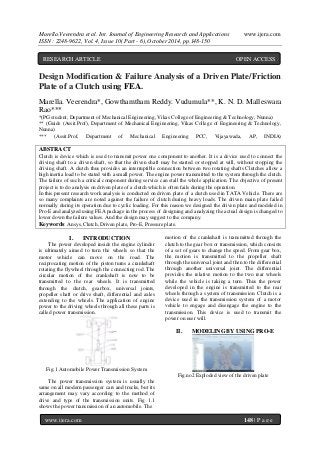
- 1. Marella.Veerendra et al. Int. Journal of Engineering Research and Applications www.ijera.com ISSN : 2248-9622, Vol. 4, Issue 10( Part - 6), October 2014, pp.148-150 www.ijera.com 148 | P a g e Design Modification & Failure Analysis of a Driven Plate/Friction Plate of a Clutch using FEA. Marella. Veerendra*, Gowthamtham Reddy. Vudumula**, K. N. D. Malleswara Rao*** *(PG student, Department of Mechanical Engineering, Vikas College of Engineering & Technology, Nunna) ** (Guide (Assit.Prof), Department of Mechanical Engineering, Vikas College of Engineering & Technology, Nunna) *** (Assit.Prof, Department of Mechanical Engineering PCC, Vijayawada, AP, INDIA) ABSTRACT Clutch is device which is used to transmit power one component to another. It is a device used to connect the driving shaft to a driven shaft, so that the driven shaft may be started or stopped at will, without stopping the driving shaft. A clutch thus provides an interruptible connection between two rotating shafts Clutches allow a high inertia load to be stated with a small power. The engine power transmitted to the system through the clutch. The failure of such a critical component during service can stall the whole application. The objective of present project is to do analysis on driven plate of a clutch which is often fails during the operation. In this present research work analysis is conducted on driven plate of a clutch used in TATA Vehicle. There are so many complaints are noted against the failure of clutch during heavy loads. The driven main plate failed normally during its operation due to cyclic loading. For this reason we designed the driven plate and modeled in Pro-E and analyzed using FEA package in the process of designing and analyzing the actual design is changed to lower down the failure values. And the design may suggest to the company. Keywords: Ansys, Clutch, Driven plate, Pro-E, Pressure plate. I. INTRODUCTION The power developed inside the engine cylinder is ultimately aimed to turn the wheels so that the motor vehicle can move on the road. The reciprocating motion of the piston turns a crankshaft rotating the flywheel through the connecting rod. The circular motion of the crankshaft is now to be transmitted to the rear wheels. It is transmitted through the clutch, gearbox, universal joints, propeller shaft or drive shaft, differential and axles extending to the wheels. The application of engine power to the driving wheels through all these parts is called power transmission. Fig.1 Automobile Power Transmission System The power transmission system is usually the same on all modern passenger cars and trucks, but its arrangement may vary according to the method of drive and type of the transmission units. Fig 1.1 shows the power transmission of an automobile. The motion of the crankshaft is transmitted through the clutch to the gear box or transmission, which consists of a set of gears to change the speed. From gear box, the motion is transmitted to the propeller shaft through the universal joint and then to the differential through another universal joint. The differential provides the relative motion to the two rear wheels while the vehicle is taking a turn. Thus the power developed in the engine is transmitted to the rear wheels through a system of transmission. Clutch is a device used in the transmission system of a motor vehicle to engage and disengage the engine to the transmission. This device is used to transmit the power on user will. II. MODELING BY USING PRO-E Fig.no2 Exploded view of the driven plate RESEARCH ARTICLE OPEN ACCESS
- 2. Marella.Veerendra et al. Int. Journal of Engineering Research and Applications www.ijera.com ISSN : 2248-9622, Vol. 4, Issue 10( Part - 6), October 2014, pp.148-150 www.ijera.com 149 | P a g e Fig.3 Assembled View Of The Driven Plate III. PARTS UNDER ANALYSIS Fig.4 Main plate crosssection Fig.5 Supporting plate crosssection IV. RESULTS & DISCUSSION Actual plate results Fig.6 Stress Intensity Fig.7 Von Mises Stress Fig.8 Max strain intensity Actual supporting plate results Fig.6 Stress Intensity Fig.7 Von Mises Stress Fig.8 Max strain intensity Results of the modified supporting plate (r=5) Fig.6 Stress Intensity Fig.7 Von Mises Stress Fig.8 Max strain intensity Results of the modified supporting plate (r=5 & t=3) Fig.6 Stress Intensity Fig.7 Von Mises Stress Fig.8 Max strain intensity V. CONCLUSION As from the analysis result of the actual side plate the maximum value of stress is very near to the theoretical endurance limit. Due to which the crack is formed on the side plate during the earlier period of the testing. In order to increase the life of the side plate of the driven plate. Some of the modifications are done on the side plate to reduce the maximum stress. Primarily the thickness of the plate is increased and this modification gives maximum stress lesser than the maximum stress of the actual side plate. Factor of safety is increased to 1.23. Alternative modification of the side plate is done by increasing the fillet radius. The maximum stress obtained by this modification is lesser when compared to the previous modification. Factor of safety is increased to 1.52. In order to reduce the maximum stress further, both the above said modifications are combined. The maximum stress is reduced further. Factor of safety is increased to 1.7. This design has highest factor of safety than the other modifications. This ultimately increases the life of the driven plate. This design is also tested practically in the lab and it is confirmed that the life of the driven plate is increased.
- 3. Marella.Veerendra et al. Int. Journal of Engineering Research and Applications www.ijera.com ISSN : 2248-9622, Vol. 4, Issue 10( Part - 6), October 2014, pp.148-150 www.ijera.com 150 | P a g e The present design analysis was done to find the failure region and reasons for failure only by onsidering the structural analysis. In future this project can be extended to thermal analysis by considering frictional effects during the operation. REFERENCES [1]. A project of the driven plate analysis by srm university student. [2]. Machine design by r.s. khurmi [3]. Psg, 2008.”design data,” kalaikathir achchagam publishers, coimbatore, india [4]. Intelligent Systems”: A Comparative StudyHindawi Publishing Corporation Applied Computational Intelligence and Soft Computing Volume 2011, Article ID 183764, 18 pages. [5]. Abbas Fadhel Ibraheem, Saad Kareem Shather & Kasim A. Khalaf, “Prediction of Cutting Forces by using Machine Parameters in end Milling Process”, Eng.&Tech. Vol.26.No.11, 2008. [6]. S. Abainia, M. Bey, N. Moussaoui and S. Gouasmia.” Prediction of Milling Forces by Integrating a Geometric and a Mechanistic Model”, Proceedings of the World Congress on Engineering 2012 Vol III WCE 2012, July 4 - 6, 2012, London, U.K. [7]. R.B.GUPTA ( 2005 ) „Automobile Engineering‟ , Sathya Prakasan Publishers. [8]. IBRAHIM ZEID (1998 ). „CAD/CAM Theory and practice‟ , Tata Mcgraw Hill. [9]. C.S. KRISHNAMOORTHY ( 1994 ) „Finite Element Analysis Theory and Programming‟ , Tata Mcgraw Hill.