1. Prof. Anjali J. Joshi, Dr. Jayant P. Modak / International Journal of Engineering Research and
Applications (IJERA) ISSN: 2248-9622 www.ijera.com
Vol. 3, Issue 2, March -April 2013, pp.189-194
A Generalized Approach for Kinematic Synthesis and Analysis of
Alternate Mechanism for Stone Crusher Using Relative Velocity
Method
Prof. Anjali J. Joshi *, Dr. Jayant P. Modak **
*(Research Student, Department of Mechanical Engineering, Priyadarshini College of engineering, Nagpur
(M.S) India)
** (Dean R&D, Department of Mechanical Engineering, Priyadarshini College of engineering, Nagpur (M.S)
India)
ABSTRACT
In this paper alternate mechanism for
design and analysis of small size stone crusher B B
mechanism is discussed. The basic idea is to B
2
optimize the design of the crusher which would 1
be best suited for stone which need crushing
force of 3 Tons. Presently for reducing sizes of
stones from 10cm x 10cm to 2.5cm x 2.5cm in A
quarries is laborious job and is done manually α
Ѳ
our approach is to design a best optimum A β φ
mechanism for said conditions.
1
O O
Keywords – Dynamic, Kinematic synthesis and 2
1 2
analysis, Sector gear, Static. A
1
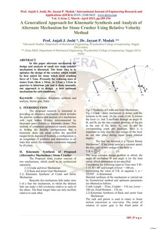
I. INTRODUCTION
The proposed research is interested in 1
Fig -1 Synthesis of Crank and lever Mechanism
providing an altenative mechanism which includes Fig 1 Crank – lever mechanism is shown with the
1
the position synthesis and analysis of a mechanism notation to be used. As the crank (Link 1) rotates
1
the lever i.e. link 3 oscillates through an angle Ѳ.
with rigid bodies (Links) interconnected by
kinematic pairs (Joints) i.e. kinematic chains. This B11and B2 are the two extreme positions of the pin
method, of completely geometrical nature, consists at 1 the end of the lever. A1 and A2 are the
in finding the feasible configurations that a corresponding crank pin positions. Here it is
kinematic chain can adopt within the specified important to note that the two swings of the lever
ranges for its degrees of freedom, a configuration is do not take place during equal crank rotation
an assignment of positions and orientations to all angles.
links that satisfy the kinematic constraints imposed The four bar function is a “Quick Return
by all joints. Mechanism”. If the crank turns at a constant speed,
the time ratio of two swings of the lever is
180 + ∝
II. Kinematic Synthesis of Proposed T. R = …………… (1)
180 − ∝
(Alternative Mechanism ) Stone Crusher The most common design problem in which, the
The Proposed stone crusher consists of angle of oscillation Ѳ and angle α (or the time
two mechanisms, which needs to be synthesized ration, which determines α) are specified.
separately. Considering the following input as Time ratio T.R=
2.1) Crank and lever Mechanism 1.15, Ѳ = 400 and Length of lever = 100 cm.
2.2) Rack and sector Gear Mechanism Substituting the value of T.R. in equation 1, α =
2.1) Kinematic Synthesis of Crank and Lever 12.5580 is determined.
Mechanism Detailed synthesis of the mechanism is carried out
Basically this mechanism falls under class by Geometrical method and optimum parameters
I of a four bar mechanism, in which the shortest are obtained as follows.
link can make a full revolution relative to each of Crank Length – 32cm, Coupler – 110 cm, Lever –
the others. The three longer links can only oscillate 100 cm, fixed Distance – 116 cm.
relative to each other. 2.2) Kinematic Synthesis of Rack and sector Gear
Mechanism
The rack and pinion is used in rotary to linear
motion conversion or vice-versa. The center of
rotation of sector gear is the fixed point of
189 | P a g e
2. Prof. Anjali J. Joshi, Dr. Jayant P. Modak / International Journal of Engineering Research and
Applications (IJERA) ISSN: 2248-9622 www.ijera.com
Vol. 3, Issue 2, March -April 2013, pp.189-194
oscillation of lever of a crank and rocker Fig -2 Synthesis of Rack and sector Gear
mechanism. As the lever oscillates in 400, the rack Mechanism
meshes with the pinion and moves left and right in
response to angular movement of oscillatory lever. III.STATIC FORCE ANALYSIS –
The design of hopper of a stone crusher is such that Graphical Method
at least two stones of size 10 cm X 10cm are to be Analyses may be required for a number of
placed at a time for crushing. So the minimum mechanism positions; however, in many cases,
distance travelled by the rack should be at least critical maximum-force positions can be identified
equal to the 20cm, which is provided by sector gear and graphical analyses performed for these
which oscillates for 400. positions only. An important advantage of the
𝜋
𝐿= Ѳ ∗ R …………….. (2) graphical
180
𝜋
20 = (40) ∗ R
180 Approach is that it provides useful insight as to the
R=28.64cm nature of the forces in the physical system.
Where, Figure below shows the angular position of crank
L=Minimum Length of Rack=20cm Ѳ=600
R=Radius of Pinion
Ѳ=Angle of oscillation
Pitch circle diameter of sector gear=D=28x
2=56cm.
Considering standard module, m= 10 mm
No. of teeth on the circumference of gear=D/m=56
𝜋∗𝐷
Circular Pitch = N ………… (3)
𝜋∗560
= 56 = 31.4159 mm
For designing sector gear which oscillates for 400,
Let,
N=Number of teeth on sector gear
Angle of oscillation ∗No .of teeth on gear
N= … (4)
Angle of One revolution
40∗56
= 360 = 6.22
Therefore, Total number of teeth on sector gear = 7
B
0
40
A
O2
OO
1
1
Fig-3 Static Force analysis – Graphical Method
The mechanism is analyzed graphically and
ultimately the torque on the crank is computed.
Mean position of rack
From the above Force polygon F23 =1.1 Tons in the
direction shown.
Crushing force at the end of pinion is considered as
3 Tons. The crank is rotating at an angular speed of
120 rpm (Anticlockwise)
F23 = -F32 = F12 =-F21=F41 = 1.1Tons.
Summing Moments about point O1 gives torque
required on the crank.
F
∑MO1= TO1A+F21 x h = 0 …..(5)
c
For equilibrium, the torque TO1A must be equal to
F21 X h. This is shown in Fig. Because the cross-
product F21 x h is clockwise, the torque must be
anticlockwise.
0 20 Cm
-20
Cm
Stroke Length
190 | P a g e
3. Prof. Anjali J. Joshi, Dr. Jayant P. Modak / International Journal of Engineering Research and
Applications (IJERA) ISSN: 2248-9622 www.ijera.com
Vol. 3, Issue 2, March -April 2013, pp.189-194
IV.DYNAMIC FORCE ANALYSYS –
Graphical Method
Dynamic force Analysis for Proposed Stone
A F21 crusher uses d'Alembert's principle can be derived
from Newton's second law.
TO1 O1
F (maG ) 0 …………… (6)
T eG (I G ) 0 ……………….. (7)
A
F41 The terms in parentheses in Eq. (6) and (7) are
called the reverse-effective force and the reverse-
effective
Fig: 4 Torque required on crank
Torque, respectively. These quantities are also
So we have calculated a torque required on the
referred to as inertia force and inertia torque. Thus,
crank which is given in a tabulated form.
we define the inertia force F, as
Fi = -maG ………………….(8)
Table: 1 Crank Angular Position with force and
Torgue required on crank Where F refers here to the summation of
Crank
Coupler Torque
external forces and T eG is the summation of
force on required on external moments, or resultant external moment,
Sr.No Angular
Link AB Crank O1A about the center of mass G
Position
(in Tons) (in Nm) This reflects the fact that a body resists any change
in its velocity by an inertia force proportional to the
1 300 1 1200 Clockwise
mass of the body and its acceleration. The inertia
0 1540 Anti-
Force acts through the center of mass G of the
2 60 1.1
Clockwise
body. The inertia torque or inertia couple C, is
2340
C i I G
0 Anti-
3 90 0.9 given by: (9)
Clockwise …
2880
4 1200 0.9 Anti-
Clockwise
2240 As indicated, the inertia torque is a pure torque or
5 1500 0.8 Anti-
Clockwise couple. From Equations (8) & (9), their directions
1760 are opposite to that of the accelerations.
6 1800 0.8 Anti-
Clockwise Substitution of Equation (8) and (9) into Equation
840 (6) and (7) leads to equations that are similar to
7 2100 0.7 Anti-
Clockwise those used for static-force analysis:
8
9
2400
2700
0.6
0.7
60 Anti-Clockwise
980 Clockwise F F F 0 ………………. (10)
e i
10
11
3000
3300
0.85
1
2040 Clockwise
3200 Clockwise
T T C 0 ……………. (11)
G eG i
V. CALCULATIONS:
12 3600 1 2600 Clockwise α2=atba/AB=4700/110=42.72rad/s2………from
acceleration diagram
Above table indicates that maximum force in a aG2=5500N/cm2……………………..From
revolution of crank on coupler AB is 1.1 Tons. acceleration diagram
AllowableStrength
191 | P a g e
4. Prof. Anjali J. Joshi, Dr. Jayant P. Modak / International Journal of Engineering Research and
Applications (IJERA) ISSN: 2248-9622 www.ijera.com
Vol. 3, Issue 2, March -April 2013, pp.189-194
forces. These forces are shown in figure, and their
EquiF3 placement is determined. For link 2 offset forces F2
h3
B is equal and parallel to inertia force F12. Therefore
F3 F2= 42460 N.
It is offset from the centre of mass G2 by a
a
perpendicular amount equal to
h2 Va h2= (IG2α2)/(m2aG2)……………………..(16)
EquiF2
A Vba O1 ,O2 h2 = (7786.35 * 42.72)/ (7.72*5500) = 7.83 cm
C And this offset is measured to the left to produce
b Vb
H2 the required clockwise direction for the inertia
O2 moment about point G2.
O1 Fc
Velocity Diagram In a similar manner the equivalent offset inertia
O1
force for link 3 is F3 = 22113 N at an offset distance
h3 = (IG3α3) /
Force Diagram O1, O2 (m3aG3)……………………………..(17)
ab
r h3 = (5850*62.5) / (7.02* 3150) = 16.53 cm
a3
X
And this offset is measured to the right to produce
the required clockwise direction for the inertia
ab
moment about point G3
Taking moment @ O1
t
ab r = (F2H2) +
a2 aa
b (F3H3)………………………………..(18)
t
a ba
= (42460 x 17) + (22113 x 10)
aba = 942950 N-cm= 9429.5 N-m.
Similarly Velocity, accelerations and
a
r
a ba
corresponding Torque at various positions are
Y calculated.
Shown in Tabulated form
Acceleration Diagram
Fig: 5 Dynamic Force Analyses – Graphical Table: 2 Crank Angular Position Vs Torque on
Method Crank Considering Dynamic Loading
𝑆 𝑋 𝑆𝑖𝑧𝑒 𝐹𝑎𝑐𝑡𝑜𝑟 𝑋 𝐼𝑔𝑛𝑜𝑟𝑎𝑛𝑐𝑒 𝐹
= Reliability Factor X Stress concentration Factor …(12) Torque required on
16800 𝑋 0.5 𝑋 0.5 Crank Angular Crank O1A
= Sr.No
0.85 X 2.2 Position Considering Dynamic
= 2245.989 N/cm2 Loading (in Nm)
But, 1 300 27253.54 Clockwise
Allowable Strength = 2 600 9429.5 Clockwise
𝑀𝑎𝑥 .𝐹𝑜𝑟𝑐𝑒 𝑜𝑛 𝑙𝑖𝑛𝑘 𝐴𝐵
…………………………. (13) 3 900 13109.08 Anti-Clockwise
Cross section of link AB
1.1 𝑥 10000 4 1200 23115.36 Anti-Clockwise
2245.989 =Cross section of link AB 5 1500 16869.08 Anti-Clockwise
Cross section of link AB = 4.91 cm2 6 1800 5273.08 Anti-Clockwise
Selecting cross section of link as 3cm x 3 cm , 7 2100 1225.88 Anti-Clockwise
m2 = Mass of Link AB = Mass density of Link x 8 2400 5190.88 Clockwise
Volume of Link…………………… (14) 9 2700 8678.8 Clockwise
=7.8 x 10-3 x 3 x 3 x110=7.72 Kg. 10 3000 22751.28 Clockwise
IG2=Mass moment of Inertia of Link AB @ C.G. = 11 3300 19385.01 Anti-Clockwise
1
12
x Mass of Link AB x(Link AB) 2………… (15) 12 3600 14389.2 Anti-Clockwise
= 7786.35Kg-cm2 Total torque =Static torque +Dynamic
Similarly we have calculated, Torque….(19)
α3 = ato2b/O2B = 6250/100 = 62.5 Table shows Total torque at various Crank
2
rad/s …………………from acceleration diagram Positions.
aG3= 3150 N/cm2……………………..From
acceleration diagram
m3 = Mass of Link O2B = 7.02 Kg.
IG3 = Mass moment of Inertia of Link O2B @ C.G.
= 5850Kg-cm2
In graphical force analysis we will account for
inertia torques by introducing equivalent inertia
192 | P a g e
5. Prof. Anjali J. Joshi, Dr. Jayant P. Modak / International Journal of Engineering Research and
Applications (IJERA) ISSN: 2248-9622 www.ijera.com
Vol. 3, Issue 2, March -April 2013, pp.189-194
Table: 3 Crank Angular Position Vs Net Torque
on Crank
Torque Torque
Crank required on required on Net
Angular Crank O1A Crank O1A Torque
Sr.
Position Considering Considering on Crank
No
(Ѳ) Static Dynamic O1A
Loading (in Loading (in (in Nm)
Nm) Nm)
300(Loaded 1200 27253.54 28453.54
1
Condition) Clockwise Clockwise Clockwise
600(Loaded 1540 Anti- 9429.5 7889.5
2
Condition) Clockwise Clockwise Clockwise
0 2340 Anti- 15449.08
90 (Loaded 13109.08
3 Clockwise Anti-
Condition) Anti-Clockwise
Clockwise
0 2880 Anti- 25995.36
120 (Loaded 23115.36
4 Clockwise Anti-
Condition) Anti-Clockwise
Clockwise
0 2240 Anti- 19136.08
150 (Loaded 16869.08
5 Clockwise Anti-
Condition) Anti-Clockwise Fig: 6 Graph of Total Torque On crank Vs One
Clockwise
1760 7033.08 revolution of crank
1800(Loaded Anti-
5273.08 Anti-
6 Clockwise Anti- Applying Newton-Cotes quadrature formula and
Condition) Clockwise
Clockwise composite Trapezoidal rule, Total area under this
2100(No 0 1225.88 Curve is calculated which represents work done per
1225.88 Anti-
7 Load Anti- revolutions.
Clockwise
Condition) Clockwise
2400(No 0
Work done per revolution=∫ 𝑇 𝑑𝜃
5190.88 5190.88 ∆Ѳ
8 Load = 2 [T1 +TN +2(T2 +T3+…….. TN-1)]…….. (21)
Clockwise Clockwise
Condition) = - 19207.06 Nm.rad
2700(No 0 ∫ 𝑇𝑑 Ѳ
8678.8 8678.8 Tmean =
9 Load ∫ 𝑑Ѳ
Clockwise Clockwise
Condition) ………………………………….(22)
3000(No 0 22751.28 22751.28 = - 3056.90 Nm (i.e. Anticlockwise)
10 Load Clockwise Clockwise
Further mean torque is calculated which decides
Condition)
the other input parameters like drive rating,
3300(No 0 19385.01 19385.01
11 Load flywheel etc.
Anti-Clockwise Anti-
Condition) Clockwise
Area under shaded portion gives a maximum
3600(No 0 14389.2 fluctuation of energy based on which flywheel is
14389.2 Anti- designed.
12 Load Anti-
Clockwise
Condition) Clockwise Based on design of complete stone crusher
mechanism the other parameters of a stone crusher
Net Torque on the crank is calculated and the like design of Motor, belt drive, Flywheel design,
actual torque required in one revolution of crank is gear box etc are decided. Figure given below shows
tabulated in the following graph. a complete layout of small capacity stone crusher
B
V F G
A
-
C
B
B O O
C FC
1 1 2
M
B
2
193 | P a g e
6. Prof. Anjali J. Joshi, Dr. Jayant P. Modak / International Journal of Engineering Research and
Applications (IJERA) ISSN: 2248-9622 www.ijera.com
Vol. 3, Issue 2, March -April 2013, pp.189-194
Similar machines can be designed which
are of same capacities. Various designs may have
advantages and disadvantages over one another.
M-Motor V-B-V-Belt Drive B1, B 2 - Based on generated data for various designs,
Bearings C-Coupling G-Gear Box mathematical model based on dimensional analysis
H
O1-A-B-O2-C-D-O3-E-Mechanism of a stone is designed. Further by multiple regressions method
Crusher using MATLAB software the best and optimum
Fig: 6 Layout of small capacity stone crusher model can be obtained.
Outcomes of calculations
Flywheel Parameters: REFERENCES:
Type of Flywheel: Solid disc geometry with inside Journal Papers:
and outside radius 1) Anjali J. Joshi, Dr. Jayant P. Modak,
Type and Density of Material: Cast Iron with Design and Development of a small
density as 7200 Kg/m3 capacity stone crusher mechanism, Indian
Speed: 900 r. p. m. Journal of Applied Research, Volume :
Inside radius: 37.8 cm 3,Issue : 2 February 2013 ,ISSN - 2249-
Outside radius: 47.3 cm 555X
Thickness: 4.73cm 2) Dr. Louis G. Reifschneider, Teaching
Total mass of flywheel: 86 Kg Kinematic Synthesis of Linkages without
Worm Gear Box: Complex Mathematics, journal of
Specifications: Worm Gear Box, Speed Reduction Industrial Technology, Volume 21,
ratio 7.5:1, Power: 55KW Number 4-October 2005 through
December.
V-Belt Drive Books:
For speed reduction from 1500 rpm to 910 rpm, 3) Dr. Habib ,MEG 373“Kinematic and
Number of belts: 8 of type 5V1250, Type of Pulley Dynamics of Machinery”, Chapter 5 Force
8V Grooves Sheaves of D Type. Analysis.
Motor: 52 KW, 4Pole, 1500rpm 4) Jack A. Collins, Henery Busby, George
Stoab, “Mechanical Design of Machine
VI. PREVIOUS WORK: Elements & Machines” Chapter 18
We have proposed one more design for Flywheel and High –Speed Rotors.
same capacity [ref.1], in which we proposed double 5) Shriniwas S. Bali, Satish Chand,
rocker mechanism instead of Rack and sector gear Transmission Angle in Mechanism
mechanism; whose required parameters are as (Triangle in mech), Pergamon Mechanism
follows: and Machine Theory 37(2002)175-195.
Flywheel Parameters: Solid disc geometry with 6) Kennth J. Waldron / Gary L. Kinzel,
inside and outside radius, made up of cast iron with Kinematice , Dynamics,& Design of
density=7200 Kg/m2of 92.49Kg. Machinery, edition 2007.
Worm Gear Box: Power: 109 KW, Speed 7) R.S. Khurmi and J.K. Gupta, Theory of
Reduction ratio 7.5:1, Machines, edition 2002
V-Belt Drive: Number of belts: 8 of type 8V1250, 8) Robert L.Norton,Machine Design,pearson
Type of Pulley 8V Grooves Sheaves of D Type. Second edition.
Motor: Power: 75 KW, 4Pole, 1500rpm 9) Amitabha Ghosh and Ashok Kumar
Mallik,Theory of Mechanisms and
VII. COMPARISION OF TWO DESIGNS Machines,Third Edition Reprint 2008.
FOR OPTIMUM SOLUTION: Theses:
An Advantages of rack and sector gear are as 10) James G. Donovan Ph. D Thesis in
follows: Minning and Mineral Engineering,
1) Power required for same capacity of stone “Fracture toughness based models for the
crusher is less. prediction of power consumption,product
2) Worm gear box of smaller size is required. size, and capacity of jaw crushers” July
3) Overall construction cost of a stone crushing 2003.
plant is less. 11) Robert L.Norton,Machine
An Advantages of double rocker mechanism Design,pearson Second edition.
[ref.1], are as follows
1) Manufacturing cost is less.
2) Easy and cost effective maintenance.
3) Overall efficient mechanism.
VIII. CONCLUSION:
194 | P a g e