![HTR
TYPE
POWER
RATING
at 70°C L
±3
*
D
±2
d
±1
W
±0.35
H
[+2/-0]
DIMENSIONS (mm) RESISTANCE
RANGE
min max
R-10A 10W 27.0 15.0 7.7 4.75 1.4 6.35 101/301 R22 1K0 9.0
R-10B 10W 27.0 15.0 7.7 5.0 3.0 8.5 101/301 R22 1K0 9.2
R-15A 15W 40.0 15.0 7.7 4.75 1.4 6.35 101/301 R27 3K0 12.5
R-15B 15W 40.0 15.0 7.7 5.0 3.0 8.5 101/301 R27 3K0 12.8
R-20A 20W 60.0 15.0 7.7 4.75 1.4 6.35 101/301 R50 5K0 20.0
R-20B 20W 60.0 15.0 7.7 5.0 3.0 8.5 101/301 R50 5K0 20.5
R-25A 25W 75.0 15.0 7.7 4.75 1.4 6.35 101/301 R50 10K 21.0
R-25B 25W 75.0 15.0 7.7 5.0 3.0 8.5 101/301 R50 10K 21.5
R-40A 40W 75.0 26.0 14.3 4.75 1.4 6.35 102/303 1R0 15K 60.0
R-40B 40W 75.0 26.0 14.3 5.0 3.0 8.5 102/303 1R0 15K 61.0
R-50A 50W 100.0 26.0 14.3 4.75 1.4 6.35 102/303 1R6 20K 75.0
R-50B 50W 100.0 26.0 14.3 5.0 3.0 8.5 102/303 1R6 20K 76.0
R-60A 60W 115.0 26.0 14.3 6.35 1.65 8.5 102/303 2R2 25K 90.0
R-60B 60W 115.0 26.0 14.3 8.0 4.3 11.0 102/303 2R2 25K 92.0
R-80A 80W 130.0 26.0 14.3 6.35 1.65 8.5 102/303 2R2 35K 96.0
R-80B 80W 130.0 26.0 14.3 8.0 4.3 11.0 102/303 2R2 35K 97.0
R-100A 100W 150.0 33.2 19.1 6.35 1.65 8.5 103/303 3R0 40K 180.0
R-100B 100W 150.0 33.2 19.1 8.0 4.3 11.0 103/303 3R0 40K 182.0
R-125A 125W 165.0 33.2 19.1 6.35 1.65 8.5 103/303 3R0 47K 183.0
R-125B 125W 165.0 33.2 19.1 8.0 4.3 11.0 103/303 3R0 47K 185.0
R-150A 150W 200.0 33.2 19.1 6.35 1.65 8.5 103/303 3R3 56K 205.0
R-150B 150W 200.0 33.2 19.1 8.0 4.3 11.0 103/303 3R3 56K 207.0
R-200A 200W 250.0 33.2 19.1 6.35 1.65 8.5 103/303 4R7 68K 293.0
R-200B 200W 250.0 33.2 19.1 8.0 4.3 11.0 103/303 4R7 68K 296.0
R-300A 300W 250.0 45.0 24.0 6.35 1.65 8.5 104/304 5R6 75K 525.0
R-300B 300W 250.0 45.0 24.0 8.0 4.3 11.0 104/304 5R6 75K 528.0
R-400A 400W 330.0 45.0 24.0 6.35 1.65 8.5 104/304 10R 100K 760.0
R-400B 400W 330.0 45.0 24.0 8.0 4.3 11.0 104/304 10R 100K 765.0
R-500A 500W 300.0 55.0 27.0 6.35 1.65 8.5 104/304 10R 100K 1150.0
R-500B 500W 300.0 55.0 27.0 8.0 4.3 11.0 104/304 10R 100K 1155.0
R-600A 600W 330.0 55.0 27.0 6.35 1.65 8.5 104/304 10R 120K 1270.0
R-600B 600W 330.0 55.0 27.0 8.0 4.3 11.0 104/304 10R 120K 1270.0
INDICATIVE
WEIGHT
PER PC
(gms)
MOUNTING
HARDWARE
AVAILABLE
* D-Dimensions given are indicative and could exceed tolerance given depending on resistance value being wound.
* Resistor types suffixed with‘A’are compatible with Amp F 187 connectors from 10 watt to 50 watt size and are compatible with Amp
250 connectors from 60 watt to 500 watt size. Resistor types suffixed with‘B’have large center holes in the lugs-refer Øld, to facilitate
attaching cables to them by using nut & bolt or soldering after threading the wires through them.
∅ ld
±0.3
WIRE WOUND
RESISTORS
SILICONE
COATED
TYPE
HIR
PHYSICAL CONFIGURATION
MOUNTING SPECIFICATIONS
e : info@htr-india.com
www.htr-india.com
Rev Date : 15/04/2017](data:image/gif;base64,R0lGODlhAQABAIAAAAAAAP///yH5BAEAAAAALAAAAAABAAEAAAIBRAA7)
Recommended
Recommended
More Related Content
What's hot
What's hot (19)
Similar to HIR - WIRE WOUND RESISTORS SILICONE COATED TYPE
Similar to HIR - WIRE WOUND RESISTORS SILICONE COATED TYPE (20)
Recently uploaded
Recently uploaded (20)
HIR - WIRE WOUND RESISTORS SILICONE COATED TYPE
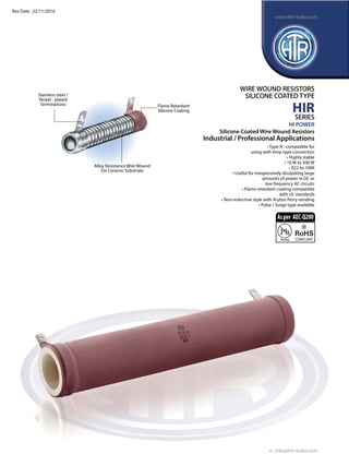
- 1. Stainless steel / Nickel - plated Terminations Flame Retardant Silicone Coating Alloy Resistance Wire Wound On Ceramic Substrate • Type‘A’- compatible for using with Amp type connectors • Highly stable • 10 W to 500 W • R22 to 100K • Useful for inexpensively dissipating large amounts of power in DC or low frequency AC circuits • Flame retardant coating compatible with UL standards • Non-inductive style with Aryton Perry winding • Pulse / Surge type available WIRE WOUND RESISTORS SILICONE COATED TYPE HIR SERIES HI POWER Silicone Coated Wire Wound Resistors Industrial / Professional Applications e : info@htr-india.com www.htr-india.com Rev Date : 15/04/2017 Asper AEC-Q200
- 2. HTR TYPE POWER RATING at 70°C L ±3 * D ±2 d ±1 W ±0.35 H [+2/-0] DIMENSIONS (mm) RESISTANCE RANGE min max R-10A 10W 27.0 15.0 7.7 4.75 1.4 6.35 101/301 R22 1K0 9.0 R-10B 10W 27.0 15.0 7.7 5.0 3.0 8.5 101/301 R22 1K0 9.2 R-15A 15W 40.0 15.0 7.7 4.75 1.4 6.35 101/301 R27 3K0 12.5 R-15B 15W 40.0 15.0 7.7 5.0 3.0 8.5 101/301 R27 3K0 12.8 R-20A 20W 60.0 15.0 7.7 4.75 1.4 6.35 101/301 R50 5K0 20.0 R-20B 20W 60.0 15.0 7.7 5.0 3.0 8.5 101/301 R50 5K0 20.5 R-25A 25W 75.0 15.0 7.7 4.75 1.4 6.35 101/301 R50 10K 21.0 R-25B 25W 75.0 15.0 7.7 5.0 3.0 8.5 101/301 R50 10K 21.5 R-40A 40W 75.0 26.0 14.3 4.75 1.4 6.35 102/303 1R0 15K 60.0 R-40B 40W 75.0 26.0 14.3 5.0 3.0 8.5 102/303 1R0 15K 61.0 R-50A 50W 100.0 26.0 14.3 4.75 1.4 6.35 102/303 1R6 20K 75.0 R-50B 50W 100.0 26.0 14.3 5.0 3.0 8.5 102/303 1R6 20K 76.0 R-60A 60W 115.0 26.0 14.3 6.35 1.65 8.5 102/303 2R2 25K 90.0 R-60B 60W 115.0 26.0 14.3 8.0 4.3 11.0 102/303 2R2 25K 92.0 R-80A 80W 130.0 26.0 14.3 6.35 1.65 8.5 102/303 2R2 35K 96.0 R-80B 80W 130.0 26.0 14.3 8.0 4.3 11.0 102/303 2R2 35K 97.0 R-100A 100W 150.0 33.2 19.1 6.35 1.65 8.5 103/303 3R0 40K 180.0 R-100B 100W 150.0 33.2 19.1 8.0 4.3 11.0 103/303 3R0 40K 182.0 R-125A 125W 165.0 33.2 19.1 6.35 1.65 8.5 103/303 3R0 47K 183.0 R-125B 125W 165.0 33.2 19.1 8.0 4.3 11.0 103/303 3R0 47K 185.0 R-150A 150W 200.0 33.2 19.1 6.35 1.65 8.5 103/303 3R3 56K 205.0 R-150B 150W 200.0 33.2 19.1 8.0 4.3 11.0 103/303 3R3 56K 207.0 R-200A 200W 250.0 33.2 19.1 6.35 1.65 8.5 103/303 4R7 68K 293.0 R-200B 200W 250.0 33.2 19.1 8.0 4.3 11.0 103/303 4R7 68K 296.0 R-300A 300W 250.0 45.0 24.0 6.35 1.65 8.5 104/304 5R6 75K 525.0 R-300B 300W 250.0 45.0 24.0 8.0 4.3 11.0 104/304 5R6 75K 528.0 R-400A 400W 330.0 45.0 24.0 6.35 1.65 8.5 104/304 10R 100K 760.0 R-400B 400W 330.0 45.0 24.0 8.0 4.3 11.0 104/304 10R 100K 765.0 R-500A 500W 300.0 55.0 27.0 6.35 1.65 8.5 104/304 10R 100K 1150.0 R-500B 500W 300.0 55.0 27.0 8.0 4.3 11.0 104/304 10R 100K 1155.0 R-600A 600W 330.0 55.0 27.0 6.35 1.65 8.5 104/304 10R 120K 1270.0 R-600B 600W 330.0 55.0 27.0 8.0 4.3 11.0 104/304 10R 120K 1270.0 INDICATIVE WEIGHT PER PC (gms) MOUNTING HARDWARE AVAILABLE * D-Dimensions given are indicative and could exceed tolerance given depending on resistance value being wound. * Resistor types suffixed with‘A’are compatible with Amp F 187 connectors from 10 watt to 50 watt size and are compatible with Amp 250 connectors from 60 watt to 500 watt size. Resistor types suffixed with‘B’have large center holes in the lugs-refer Øld, to facilitate attaching cables to them by using nut & bolt or soldering after threading the wires through them. ∅ ld ±0.3 WIRE WOUND RESISTORS SILICONE COATED TYPE HIR PHYSICAL CONFIGURATION MOUNTING SPECIFICATIONS e : info@htr-india.com www.htr-india.com Rev Date : 15/04/2017
- 3. ELECTRICAL AND ENVIRONMENTAL CHARACTERISTICS PARAMETER/PERFORMANCE TEST/TEST METHOD PERFORMANCE REQUIREMENTS BRACKET TYPE Y ±1.0mm Z ±2mm H ±2mm MOUNTING SLOT ±0.5mm C ±2mm B ±2mm 101 12.0 22.0 25.0 5.5 X 8.5 19.0 35.0 102 20.0 25.0 33.0 5.5 X 11.0 20.0 46.0 103 32.0 30.0 37.0 7.0 X 11.0 22.0 54.0 104 48.0 32.0 57.0 7.0 X 11.0 23.0 82.0 BRACKET TYPE X (APPROXIMATE) (mm) 301 12.0 303 15.0 304 16.0 WIRE WOUND RESISTORS SILICONE COATED TYPE HIR Power Rating (Rated Ambient Temperature) Full power dissipation at 70°C and linearly derated to zero at 350°C (Refer derating curve above) Resistance Tolerances Available ±10% [K]; ±5% [J]; ±3% [H]; ±2%[G]; ±1% [F] Temperature Range -55°C to +350°C with suitable derating as per derating curve above Voltage Rating / Limiting Voltage / Max. Working Voltage V = P x R Maximum Overload Voltage Varies depending on resistance value, duration of overload and type of pulse waveform (Contact Factory for details) Voltage Proof / Dielectric Withstanding Voltage ∆R ± (1% + R05) (Based on limiting voltage x 2 or 500V whichever is applicable for 60 secs) Short Time Overload (10 x Rated power for 5 secs) ∆R ± [2% + R05] Temperature Co-efficient of Resistance <R10 ± 120 ppm/°C ; <1R0 ± 80 ppm/°C ; <100R ± 60 ppm/°C ; >100R ± 90 ppm/°C or 30 ppm/°C (depending on wire selected) Insulation Resistance (Test Method no. 302 of MIL 202F) > 1000M (Dry) >100M (Wet) Thermal Shock (Limiting voltage applied until ∆R ± [2% + R05] temperature stabilizes and then placed in cold chamber -55°C for 15 minutes) Damp Heat (Steady State) / Humidity ∆R ± [3% + R05] (70°C at 95% R.H for 250 hours) Low Temperature Storage (-55°C for 1 day) ∆R ± [≤2% + R05] Extreme Heat Storage (225 hours at +350°C) ∆R ± [≤2% + R05] Endurance - Load Life [70°C with limiting voltage - ∆R ± [≤3% + R05] 1.5 hours on / 0.5 hours off for 1000 hours] Solvent Resistance [IPA for 60 secs ± 10 secs] No effect on coating / marking. Notes : 1. Resistance values below and above the shown resistance range are possible on request. 2. Non-inductive types in this series are possible. 3. Dimensions given are to be used as a guide only, they can be varied to a certain extent due to technical reasons. For example, larger terminals may be used for very low values. 4. Pulse / Surge resistors are available in this series. TYPICAL APPLICATIONS 1. Grid resistor 2. Voltage dropping resistor 3. Bias supply resistor 4. High voltage bleeder resistor in power supplies 5. Voltage divider networks 6. Filament dropping resistor 7. Load resistor. 1. RoHS version - R20A * 2. For Pulse Type - R20A I 3. For Non-inductive Type - N R20A ORDERING INFORMATION Series HTR Type Packing Resistance Value Tolerance Type of Mounting Hardware HIR R20A/R20A* Bulk R20A/R20A* 100R J 101 / 301 e : info@htr-india.com www.htr-india.com Rev Date : 15/04/2017