Artificial intelligence in the post-deep learning era
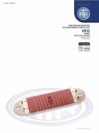
WIRE WOUND RESISTORS SPEC SHEET
1. e : info@htr-india.com
www.htr-india.com
WIRE WOUND RESISTORS
SILICONE/cement COATED TYPE
HFO
SERIES
PRECISION POWER
• 40 W to 125 W
• R 10 to 33 K
Rev Date : 18/09/2021
AEC-Q200Qualified
2. HTR TYPE POWER ResistanCE Typicalwt.
RATING L1 (max) L2±2 L3±2 RANGE
PER PC (Gms)
HFO 30W* 30W 67.0 47.0 32.0 R 10 to 5 K 20
HFO 40W* 40W 85.0 67.0 51.0 R 10 to 8 K 33
HFO 80W* 80W 125.0 107.0 90.0 R 10 to 18 K 50
HFO 100W* 100W 155.0 137.0 120.0 R 10 to 27 K 62
HFO 125W* 125W 188.0 170.0 153.0 R 10 to 33 K 75
HFO 200W* 200W 236.0 200.0 200.0 R 10 to 40 K 100
PHYSICAL CONFIGURATION
DERATING CURVE
e : info@htr-india.com
WIRE WOUND
RESISTORS
SILICONE/
COATED TYPE
HFO
www.htr-india.com
100
60
20
25 50 70 100 150 175 200 225 250 275 300 325 350
Ambient Temperature [oC]
Rated
Dissipation[%]
0
DIMENSIONS (mm)
Notes : 1. For non-inductive resistors, please prefix 'N' before the HTR type eg. NHFO
2. For impulse type, please suffix HTR type with 'I' eg. HFOI
5.5
9
3
L1
L2
L3 15
+1
-0
15
+1
-0
30 (max)
10 to 11.5 mm
35 (max)
Rev Date : 18/09/2021
3. PRINTING / MARKING :
HTR logo, type, value, tolerance & date code
flammability :
The resistor coating shall not emit fire / flame which even if it occurs will self extinguish within seconds.
PACKING :
1. For inductance details in non inductive types, please indicate resistance value required.
2. For pulse types please indicate derated pulse requirements.
WIRE WOUND
RESISTORS
SILICONE/
COATED TYPE
HFO
www.htr-india.com
TYPE / VALUE / TOL. QUANTITY SMALL BOX TYPE SMALL BOX SIZE PACKING TYPE
HFO 40W* / NHFO 40W* 30 pcs. 'A' type 200mm X 150mm X 70mm Bulk Packing
HFO 80W* / NHFO 80W* 25 pcs. 'A' type 200mm X 150mm X 70mm Bulk Packing
HFO 100W* / NHFO 100W* 20 pcs. 'b' type 295mm X 140mm X 80mm Bulk Packing
HFO 125W* / NHFO 125W* 20 pcs. 'b' type 295mm X 140mm X 80mm Bulk Packing
e : info@htr-india.com
Rev Date : 18/09/2021
Power Rating Full power dissipation at upto 70°C and linearly derated down
(Rated Ambient Temperature) to zero at 350°C. [See Derating Curve above]
Temperature Range - 40° C to + 250° C (with suitable de-rating as per curve shown)
ResistanceTolerance Available ± 10% (K) / ± 5% (J)
Voltage Rating / LimitingVoltage / Max.WorkingVoltage P x R
Insulation Resistance (Test Method No. 302 of MIL 202F) ≥1000 MΩ
ShortTime Overload (10 X Rated power for 5 sec.) Max. ∆R ± (2% + R05)
Temperature Co-efficient of Resistance (Typical) ± 200 PPM / °C
Damp Heat (Steady State) / Humidity ∆R ± (3% + R05)
(70° C at 95% R.H. for 250 hours )
Solvent Resistance (IPA for 60 secs. ± 10 secs.) No effect on coating / marking
ELECTRICAL SPECIFICATION
PARAMETER REQUIREMENTS
![HTR TYPE POWER ResistanCE Typicalwt.
RATING L1 (max) L2±2 L3±2 RANGE
PER PC (Gms)
HFO 30W* 30W 67.0 47.0 32.0 R 10 to 5 K 20
HFO 40W* 40W 85.0 67.0 51.0 R 10 to 8 K 33
HFO 80W* 80W 125.0 107.0 90.0 R 10 to 18 K 50
HFO 100W* 100W 155.0 137.0 120.0 R 10 to 27 K 62
HFO 125W* 125W 188.0 170.0 153.0 R 10 to 33 K 75
HFO 200W* 200W 236.0 200.0 200.0 R 10 to 40 K 100
PHYSICAL CONFIGURATION
DERATING CURVE
e : info@htr-india.com
WIRE WOUND
RESISTORS
SILICONE/
COATED TYPE
HFO
www.htr-india.com
100
60
20
25 50 70 100 150 175 200 225 250 275 300 325 350
Ambient Temperature [oC]
Rated
Dissipation[%]
0
DIMENSIONS (mm)
Notes : 1. For non-inductive resistors, please prefix 'N' before the HTR type eg. NHFO
2. For impulse type, please suffix HTR type with 'I' eg. HFOI
5.5
9
3
L1
L2
L3 15
+1
-0
15
+1
-0
30 (max)
10 to 11.5 mm
35 (max)
Rev Date : 18/09/2021](data:image/gif;base64,R0lGODlhAQABAIAAAAAAAP///yH5BAEAAAAALAAAAAABAAEAAAIBRAA7)