Apidays Singapore 2024 - Building Digital Trust in a Digital Economy by Veron...
Lisbonne
1. Use of Centrifuge Tests for the Validation of Innovative Concepts in Foundation
Engineering
J. Garnier
Head of Soil Investigations and Soil Mechanics Division, Laboratoire Central des Ponts et Chaussées, Nantes, France
A. Pecker
Chairman Managing Director, Géodynamique et Structure, Bagneux, France
ABSTRACT: The design of important civil engineering structures often introduces new concepts which have
not be validated by previous experience. Extensive use of numerical modeling may help understand the
behavior of structures under extreme loading conditions. However, this modeling requires an experimental
validation that only centrifuge tests may offer. This use of centrifuge tests as a validation tool is illustrated for
the foundations of the Rion Antirion bridge (Greece).
1 INTRODUCTION
The design and the conception of important civil
engineering structures require the use of
exceptional tools for numerical modeling and
experimental validation. Among the most
appropriate experimental tools, model tests take up
a privileged place. The complex behavior of
geomaterials encountered either in foundation or in
the structure itself (earth dams for instance),
requires that model tests be realized with the
original material. This requirement, and the strong
stress dependence of the behavior of geomaterials
impose that the gravity field be adequately
reproduced.
This paper illustrates the contribution of
centrifuge tests in the validation of a new
foundation concept in seismic areas. This
innovative foundation concept is presently being
implemented for the Rion Antirion bridge in
Greece. Coupled to extensive numerical modeling,
these tests proved the validity of the concept and of
the theoretical tools developed for design.
2 DESCRIPTION OF THE STRUCTURE
The Rion Antirion bridge is a unique structure
which, within the framework of a B.O.T. contract,
has been granted to the French Company Dumez-
GTM by the Greek government. This bridge is
located near Patras, 250 km west of Athens, and
will constitute a fixed link between the Peloponese
and the Continent. The main bridge is a three
spans cabled-stayed structure, with a total length of
2 290 m; the central spans are 560 m long each. It
is located in exceptional environmental conditions
characterized by a deep water depth (65 m), weak
foundation soils composed of alluvial deposits
(alternate layers of silty sands, sandy clays and
medium plasticity clays) and a high seismic design
motion (peak ground acceleration of 0.48 g at the
seabed level). (Combault - Morand 1998; Pecker -
Teyssandier 1998)).
To accommodate these environmental
conditions, the solution chosen by Dumez-GTM,
the designer, consists in gravity base caissons
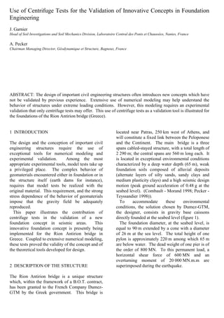
directly founded at the seabed level (figure 1).
The foundation diameter, at the seabed level, is
equal to 90 m extended by a cone with a diameter
of 26 m at the sea level. The total height of one
pylon is approximately 220 m among which 65 m
are below water. The dead weight of one pier is of
the order of 800 MN. To this permanent load, a
horizontal shear force of 600 MN and an
overturning moment of 20 000 MN.m.m are
superimposed during the earthquake.
2. Figure 1: Pier Elevation
In view of the poor quality of the foundation
soils, a direction foundation on the in-situ soils
cannot be foreseen and some kind of soil
improvement is required. The final scheme which
has been chosen is presented in figure 2; it consists
of stiff inclusions driven at close spacing below
and outside the foundation. At the present design
stage, 270 hollow steel pipes, 2 m in diameter,
20 mm thick and 25 m to 30 m long, are driven at a
square mesh of 7 m x 7 m (figure 2).
Figure 2. Pier foundation
These inclusions are not connected to the raft and
a free draining gravel bed layer is laid on top of the
inclusions below the raft. This layer prevents
suction, allows uplift and sliding during the
seismic excitation. This arrangement, which
enforces a capacity design philosophy in
foundation engineering (Pecker 1998) limits the
forces and moments transmitted to the
superstructure and to the foundation soils.
3 OBJECTIVES OF THE CENTRIFUGE TESTS
This totally innovative concept, at least in seismic
areas, clearly calls for extensive theoretical
analyses and experimental validation. As
sophisticated as can be, the theoretical and
numerical tools do not have the capacity of
modeling all the details of the behavior of this
complex scheme during an earthquake. Centrifuge
model tests were therefore undertaken with a three-
fold objective:
- validate the theoretical predictions of the
ultimate bearing capacity of the foundation under
monotonically increasing shear force and
overturning moment,
- identify the failure mechanism of the foundation
under these combined loads,
- assess the behavior of the foundation under
various cyclic load paths.
4 DESCRIPTION OF THE CENTRIFUGE
FACILITY AND TEST SET UP
The three tests have been performed in the 200 g-ton
geotechnical centrifuge at the LCPC Nantes center.
The centrifuge was described by Corte and Garnier
(1986). It is designed to carry a 2000 kg payload to
100 g accelerations, the bucket surface is at a radius
of 5.5 m and the platform has a working space of 1.4
m by 1.1 m.
All tests have been carried out at 100 g on
models at a scale of 1/100 (Figure 3). The
dimensions of the corresponding prototype are as
follows :
Radius of the circular footing : Bf = 30 m
Inclusions: Length and diameter: D = 8.5 m and
Bi = 0.67 m
Wall thickness t = 6.7 mm (steel)
Stiffness EI = 158 MN.m2
Thickness of the ballast layer : 1.2 m
Figure 3. Model foundation (scale 1/100)
Foundation
Scour protection
Movable mass
3. The soil material has been sampled at location
of pier N17 of the Antirion approach viaduct and
sent to the laboratory. The clay is dried at 60° for 24
hours, water is added to bring the water content to
about w = 80% and the slurry is mixed under
vacuum during 4 hours to get a homogeneous
material. The slurry poured into the cylindrical
containers, 895 mm wide, is then consolidated in
four successive layers. After consolidation, the 350
inclusions are jacked into the clay sample at a square
mesh of 23 mm (2.3 m at prototype scale). The
ballast layer is simulated by Fontainebleau sand
pluviated on top of the clay (Figure 4).
Figure 4. Inclusions jacked into the clay bed
The models are instrumented to measure :
- Pore pressures at different locations below the
foundation
- Soil settlements
- Vertical and horizontal displacements of the
footing
- Water table level (kept close to the clay layer
surface)
- Applied loads (shear force and overturning
moment)
- Bending moment in 2 or 3 inclusions (Figure 4).
A cone penetrometer actuator or a vane test
device are located onto the container to determine
the clay characteristics during the 100 g tests. For
the clay used in the tests, a linear relationship has
been obtained between CPT tip resistance qc and
undrained shear strength Su both measured in flight:
Su = qc / 14.7
The loads applied to the foundation system have
three independent components:
- vertical load V kept constant during the whole
tests (V = 8.9 kN in Test 1 and 9.3 kN in Tests 2
and 3, in prototype conditions). This load is
simulated by the dead weight of the foundation.
- horizontal shear force T applied at an elevation
h=118 mm (11.8 m in prototype conditions) above
the foundation level (top of the ballast layer). A
hydraulic servo-actuator is used and the horizontal
load T produces an overturning moment T.h.
- additional overturning moment M corresponding
to a vertical load eccentricity. This overturning
moment is obtained by displacing a carriage and a
movable mass using an electric motor and an
endless screw (Figure 3). The position of the
carriage is monitored by a displacement transducer.
An adjustable counterweight allows to balance all
moments to zero when the movable mass is at its
central position.
A typical loading path is shown in Figure 5
below.
Figure 5. Typical load path
Path OK-OK’ corresponds to cyclic horizontal
shear force T when the vertical load is applied at
the center of the foundation. Paths AB and DC are
also cyclic shear force but the vertical load is
eccentric (additional constant overturning
moment). Paths AD and BC are cyclic overturning
moment under a constant horizontal shear force T.
Table 1 presents the loading programs of the
three tests. In order to be in undrained conditions
in the clay beds, frequency for cyclic loading is
chosen as 0.1 Hz in shear T loading and 0.02 Hz in
combined T-M loading.
Table 1. Loading programs in Tests 1, 2 and 3 in
prototype conditions
Test
Sequence
Test 1 Test 2 Test 3
1 10 cycles
T=+/-6.5 MN
10 cycles
T=+/-5 MN
10 cycles
T=+/-15 MN
2 10 cycles
T=+/- 14 MN
10 cycles
T=+/-15 MN
10 cycles
T=+/-15 MN and
M=+/-70 MN.m
3 10 cycles
T=+/- 35 MN
10 cycles
T=+/-15 MN and
M =+/-70 MN.m
10 cycles
T=+/-35 MN
Instrumented tubes
DO
Overturning moment M
Shear force T
A
K
B
C
K’
4. 4 Static loading T
to failure
10 cycles
T=+/-35 MN and
M=+/-170 MN.m
5 cycles
T=+/-35 MN and
M=+/-170 MN.m
5 Static loading T up to
failure
5 cycles
T=+/-35 MN
6 Static loading T up to
failure
5 TESTS RESULTS
Each clay model is consolidated at 100 g for two to
five hours before starting the loading tests. The
consolidation ratio at the end of this 100 g
consolidation is close to U=100% in the upper
reinforced layers. On the whole clay beds, U ranges
from 74% to 95% depending on the clay sample.
Results of the CPT tests performed in flight in
Test 2 at the end of the 100 g consolidation are
shown in Figure 6 and compared to the shear
strength profile observed on site:
Su = 30 + 2.8 z (Su in kPa, z in m)
It is obviously not possible to present all loading
test results and only some data from Test 2 are
shown as examples. First, Figure 7 gives the main
recorded values vs. time in model units. The
loading sequences 1 to 5 indicated in Table 1 are
clearly seen in the shear force T vs. time curve. Figure 6. Shear strength profiles from in flight CPT
tests performed into the clay sample (Test 2)
0
2
4
6
8
Vertical
displacement
(mm)
-5
0
5
10
15
20
Horizontal
displacement
(mm)
0 100 200 300 400 500 600 700 800 900 1000 1100 1200 1300 1400 1500
Time (seconde)
-500
-250
0
250
500
Shearforce
(daN)
D69
D68
Vertical Displacement of the foundation
Horizontal displacement of the foundation
Load sequences
1 2 3 4 5
Shear force T
-20
0
20
40
60
80
Porepressure
(kPa)
Pore presures - 128 mm below the clay surface
100 mm out of
the vertical
below the center
of the foundation
0.0 0.2 0.4 0.6 0.8 1.0 1.2 1.4 1.6 1.8 2.0
-32
-28
-24
-20
-16
-12
-8
-4
0
4
0 20 40 60 80 100 120
Undrained shear strength (kPa) with ratio Qc/Cu = 14.8
Layer n°1 : saturated sand layer
Final clay table
Ballast (Fontainebleau sand)
Inclusion
CPT Tip resistance (MPa)
Prototypedepthzp(meter)
Cu(kPa)=2.8Z(m)+30
5. Figure 7. Test 2: horizontal load T, vertical and horizontal foundation displacements, pore pressure vs. time in
model conditions.
An example of relationship observed between
foundation displacement and cyclic shear force is
shown in Figure 8 corresponding to sequence 2. In
this case, large hysteresis is seen but displacements
stabilize with cycles.
Figure 8. Test 2 : Horizontal displacement of the
foundation vs. cyclic shear force T (sequence 2)
Tests have also shown that pore pressures may
develop during loading. Figure 9 gives
measurements done during sequence 4 by a PPT
placed 12.8 m deep in the clay and 10 m out of the
vertical of the center of the foundation in the
direction of loading. The pore pressure variation
due to the five cycles goes from - 20 kPa to
+80 kPa. It is sensitive to both the additional
overturning moment M and to the shear force T.
Figure 9. Test 2: Excess of pore pressure due to
cyclic loading 12.8 m deep in the clay and 10 m
out of the vertical of the foundation in the loading
direction (sequence 4).
The inclusions participate significantly in the
response of the foundation system even under
relatively small loads. Figure 10 presents the
bending moment profiles observed in inclusion P5
during static loading up to failure (sequence 5).
This 8.5 m long inclusion is placed at a distance of
13.8 m from the center of the foundation in the
loading direction (Figure 12). Maximum bending
moment is located at mid-depth and increases with
the applied horizontal shear force. When the load
reaches T = 45 MN, bending moment in inclusion
increases much more rapidly.
Figure 10. Test 2 : Bending moment vs. depth in
inclusion P5 during loading sequence 5
This critical load about 45 MN is also observed
in the load vs. foundation displacement plotted in
Figure 11. This figure presents the response of the
foundation system to the final static T loading up
to failure (sequence 5 in table 1). At the beginning
of sequence 5, the horizontal displacement of the
foundation is 0.48 m due to the previous cyclic
sequences 1 to 4.
-0.02 -0.01 0.00 0.01 0.02 0.03 0.04
Horizontal displacement (meter)
-18
-16
-14
-12
-8
-6
-4
-2
2
4
6
8
12
14
16
18
-20
-10
0
10
20
ShearforceT(MN)
Pull
Push
-1.8 -1.3 -0.8 -0.3 0.3-2.0 -1.5 -1.0 -0.5 0.0 0.5
Bending moment in the inclusion P5 (MN*m)
-8
-7
-6
-5
-4
-3
-2
-1
0
1
Depthintotheclay(meter)
P5-4
P5-3
P5-5
P5-2
P5-1
Clay bed
Ballast layer Inclusion P5
Pull Push
Shear force T
25.0 MN
35.0 MN
38.1 MN
42.0 MN
44.0 MN
46.0 MN
48.1 MN
50.2 MN
-600 -400 -200 0 200 400 600
Additional overturning moment (MN*m)
-30
-10
10
30
50
70
-40
-20
0
20
40
60
80
Porepressure(kPa)
Pull
Push
-40 -30 -20 -10 0 10 20 30 40
Horizontal shear force T (MN)
-30
-10
10
30
50
70
-40
-20
0
20
40
60
80
Pull
Push
0
5
10
15
20
25
30
35
40
45
50
55
60
HorizontalshearforceT(MN)
Pull
0.0 0.2 0.4 0.6 0.8 1.0 1.2 1.4 1.6 1.8 2.0
Horizontal foundation displacement (meter)
6. Figure 11: Test 2: Horizontal shear force vs.
foundation displacement in loading sequence 5
The loading curve in Figure 11 indicates a very
stiff response up to a load about 43 MN at which
the relative horizontal displacement is only 0.12 m.
Displacement increases more rapidly after this
T=43 MN load that corresponds to failure. The
displacement controlled loading process continues
up to a horizontal displacement of 1.32 m (1.8 m
from the beginning of the test). The carried shear
force T is then close to 50 MN.
A view of a vertical cut done in the model after
the centrifuge loading test is shown in Figure 12.
The print of the circular footing is clearly seen and
the figure also indicates that clay deformation and
inclusions rotation are much larger at the front of
the footing in the loading direction.
Instrumented
inclusion P5
Loading
direction
Figure 12. Test 2 : Vertical cut of the model after the
loading test along the footing diameter in the
loading direction.
All three loading tests of foundation resting on
the reinforced clay have shown that neither the
initial stiffness nor the ultimate resistance to
horizontal loads are affected by the previous cyclic
loading sequences even if some have been very
severe.
6 COMPARISON WITH THEORETICAL
ANALYSES
The theoretical tools developed to analyze the
behavior of the reinforced soil are based on a limit
analysis method (yield design theory; Salençon
1990) and on the finite element method. The yield
design theory allows the determination of the
ultimate loads that the foundation can withstand
and therefore provides a means of estimating the
ultimate bearing capacity under various monotonic
load paths. The finite element analyses give
additional information, the displacements and the
rotations of the foundation, and provide a means of
estimating its seismic behavior.
Due to the space limitations, the results of the
centrifuge tests will be compared only to those of
the yield design theory. Figure 13 presents the
kinematic mechanism used in the yield design
theory (Pecker, Salençon 1998). Under the
combined effect of the vertical load, horizontal
shear force and overturning moment, the
foundation undergoes a rotation around point Ω,
uplift along its left edge and the inclusions under
the right edge are strained and displaced; the
maximum bending moment occurs approximately
at mid-height of the inclusions, at the intersection
of the inclusions and of the kinematic mechanism.
These results predicted by the yield design theory
are in very good agreement with those observed
during the centrifuge test: see figures 10 and 12 for
comparison (taking into consideration that in
figure 12 the load is acting to the left whereas in
figure 13 it is directed to the right).
Figure 13. Kinematic mechanism
It is interesting to note that the finite element
analyses predict the same failure mechanisms.
For the three tests carried out in the centrifuge
facility in Nantes and for five other tests carried
out in another centrifuge facility in Bordeaux, the
results of which are not reported herein, figure 14
presents the comparison between the computed
failure loads (yield design theory) and the
measured ones. In Nantes, those failure loads were
measured after cyclic loading, whereas in
Bordeaux, they were measured without any prior
cyclic loads. In Nantes, the testing arrangement is
identical between the three tests and the load paths
are varied; in Bordeaux, the load path is identical
in the five tests but the other parameters are varied
(number of inclusions, soil strength, vertical load).
It appears from figure 14 that the trends are
correctly predicted, that the predictions and
Ω
ω
B
λΒ
ε''
α µ
δ
F
7. measurements are in very good agreement for the
Nantes tests and that the failure loads are
underestimated for the Bordeaux tests. However,
during the tests in Bordeaux, it was noticed that at
failure, significant changes in the initial geometry
of the system (formation of a soil bulging at the
front of the foundation) occur and that the failure
loads were measured at very large displacements.
If the "failure" loads are taken at the start of the
changes in geometry, the agreement between
predictions and measurements is also very good.
Figure 14. Comparison of measured and computed
failure loads
Finally, the cyclic tests have shown that the system
exhibits a significant energy dissipation capacity
with the formation of fat hysteresis loops during
cyclic loading. The equivalent damping ratio
computed from the hysteresis loops of figure 8 is
equal to 18%, whereas the theoretical predictions
from the finite element analyses are of the order of
15% at the same load level.
In addition, even at very high cyclic load levels
(75% to 80% of the failure load), the system
exhibits very small degradation; the hysteresis
loops stabilize after a few number of cycles
(figure 8); the permanent excess pore pressure is
only a small fraction (30%) of the initial
hydrostatic pressure.
7 CONCLUSION
The centrifuge model tests have permitted the
validation of this innovative foundation concept
proposed for the foundations of the Rion Antirion
bridge. In addition, they were used to calibrate the
theoretical analyses and numerical tools developed
for the design of the foundations which requires
extensive parametric studies, which cannot
obviously be carried out with the model tests.
REFERENCES
Combault J., Morand P. 1998. The exceptional
structure of the Rion Antirion bridge in Greece.
Proceedings of the IABSE Conference - Kobe
(Japan).
Corté J.F., Garnier J. 1986. Une centrifugeuse pour
la recherche en géotechnique. Bull. Liais. Labo.
P. et Ch. 146: 5-28
Pecker A., Teyssandier J.P. 1998. Seismic design
for the Rion Antirion Bridge", Proc. Instn. Civ.
Eng. Geotech. Engng., 131 pp. 4-11 - Paper
11311.
Pecker A 1998. Capacity design principles for
shallow foundations in seismic areas. Keynote
lecture, Proceedings XIth Europ. Conf. on
Earthquake Engineering. Eds. Bisch, Labbé,
Pecker - Balkema.
Pecker A., Salençon J. 1998. Innovative concepts
in foundation engineering. 2nd
Japan-UK
Workshop on implications of recent earthquakes
on seismic risk, Tokyo Institute of Technology,
April 6-9, 1998.
Salençon J. 1990. Introduction to the yield design
theory. European Journal of Mechanics
A/Solids 9, n° 5, pp. 477-500.
0
20
40
60
80
100
120
0 20 40 60 80 100 120
Measured failure load (MN)
Computedfailureload(MN)