
Recommended
Recommended
More Related Content
What's hot
What's hot (20)
Similar to Installation instructions for retrofitting a cruise control regulator in the Golf IV, Golf IV Variant, Bora, Bora Variant with TDi petrol engine with electronic throttle control (E-Gas)
Similar to Installation instructions for retrofitting a cruise control regulator in the Golf IV, Golf IV Variant, Bora, Bora Variant with TDi petrol engine with electronic throttle control (E-Gas) (20)
More from degarden
More from degarden (20)
Recently uploaded
Recently uploaded (20)
Installation instructions for retrofitting a cruise control regulator in the Golf IV, Golf IV Variant, Bora, Bora Variant with TDi petrol engine with electronic throttle control (E-Gas)
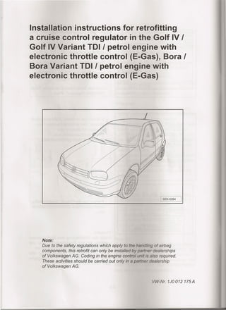
- 1. Installation instructions for retrofitting a cruise control regulator in the Golf IV ! Golf IV Variant TOl! petrol engine with electronic throttle control (E-Gas), Bora ! Bora Variant TOl! petrol engine with electronic throttle control (E-Gas) -: SEK-0354 I Note: Due to the safety regulatians which apply to the hanG~'ingaf airbag campanents, this retrafit can anly be installed by pertner dealerships af Valkswagen AG. Gading in the engine cantral unit s: eiso required. These activities shauld be carried aut anly in a penner aeelership af Valkswagen AG. -Nr.1J0012175A
- 2. e service kit: mn switch :1n~iOn;al" dicator switch with switch ess for CCS (interior) ess for CCS r.s:a;.;3tJc~n description ools, workshop equipment, measuring equipment and accesseries required anual "Body Installation erior" anual "Electrical System" rrent Flow Diagrams, cal Fault Finding and Fitting ocations 332 Torque spanner - 2 m) 51/B, VAS 5052 Vehicle sis, Measuring and Information 53 Vehicle Diagnostic System 8 Wiring Harness Repair Set p")CE~ as follows: sconnect the battery ground 6. o es: ain the radio code before .scotmec "ng the battery. . = ...t- e lIowing steps, it is essential ol/ow the repair manual l s allation Work, Interior in e 69. Important! Work on the airbag system may be carried out only be trained specialists. The relevant safety requirements must be observed, see Safety Notes on the Airbag in the Repair Manual (Chapter 69). -2-
- 3. I SEK-0340 I I SEK-0340 I - Release the steering column adjusting mechanism. - Pull the steering wheel -1- out and push it into the upper position. - Secure the steering column adjusting mechanisrn. - Turn the steering wheel -1- until the spoke of the steering wheel is vertical. :1-":-'IUA- .75 mm long er into me hole in the steering wnee, retainer from the rear (insert screv.-dr!ver about 45 mm). - Push the screv•.driver upwards Arrow. This pushes :.~esecuring clamp -6- backwarris a.-:::: releases the snap hook -3- en ::-e airbag -4-. - Use the SG.TF- pwcedure to release the hook on ms ÛäL5:- side. ~..:t ms :;.:..:g connection -2- on ;::-;::set it aside carefully. eel -1- to the eels are pointed - Rem ent screw -5-. - Pull stee - -eel off of the -3-
- 4. SEK~ - 'int sacket screw is treated = seesent, and can be used up to _.-= = zcnch mark after each time it is =~r:G tarque 60 Nm, see repair - =''='--'e the attachment screws -2-, -4- an the trim of the steering _____.- switch. - ~=::-=;e the attachment screws -1- - _c. :.~ehandle of the steering colum - :-::"'...:'3"':.:1gmechanism. =::::he handle and remove the __ Si"::im for the steering column -::; upper trim -1- in lrection of the arrow A -. smove the trim top -2- in îrection of the arrow B - fr,
- 5. I SEK-0003 I ion -1- to ::-c"~JL "z: :~2..:ps -arrows- . 9 and pull ~ -F138- must !XI:" z" :.-s centre position -= ====s if necessary). ,..,...'"·•.......n switch - Disco to the 5:=-= remove lug connections switch and - Rem column switch. ~=tr::-.c':<::'":~lug on the steering -- a screwdriver -=:::::;:~la indicator switch viper switch. - Replace rre ·:f:,;5CÛonalindicator switch us ~~ me cirectional indicator switch wr.;;. ces contalnee in the service -5-
- 6. - ,~~::t:ptriS .•en-hand trim from the fuse r.-c-!Iier G:: me dashboard. 1 2 SEK·O~;; - 1'-!:i.a:~1CiS .eft-hand trim -1- all the way. - I:::'='::-J:!::t& :.-:atattachment screws -3- 'he right-hand trim -2-. :c:..e:.::ne CCS wiring harness to the ,",?:..';::'=-lal indicator switch and fasten arness to the existing cable - ::::,'-r::.= :.~enew wiring harness from the =--=.::::alindicator switch to the ~ electrio system in the footwell. - '=:=;'~=-7'; -'•..•e wiring harness with cable - ;:::~'=F.~ethe fixing nuts ~äS- and remove the relay -.-- -1- together with the relay plate: -'=-=-=ssaryalso release the lower =7L=--:: connections on the relay
- 7. ~- I ---- 2 ~_____ , '~=~ ~ ~~-====-~ ~ <§~ SEK-0362 I - Lever the ca wiper rad . -arrows-off of the a suitable screwdriver. - Remove me arms and re nuts of the . e the wiper arms. - Pull off the - For vehicles remove the a see Repair Ma System"_ o model year 19 ment screws -2-, al "Electrical - Remove the cover fram the polle filter. - Unclip the trim on both sides fram me fender inner. - Carefully press the cowl upwards a out - Disconneet the connecting plug on me wiper motor. - Remove the attachment screws (M6 -arrows- and take off the washers. - Remove the wiper frame together the wiper motor. -7-
- 8. ~ e me cover on the electrical box --"" reservoir. - xe.ease the 10-pin connector (T1Oe) -arrow- from the bracket. - Pull the 10-pin connector (T1Oe) -2- through to the footwell. - Release the lock -1- from the 10-pin ector (T1Oe) -2-. -8-
- 9. - Insert the individual connecting connecting cables (with labelled tags) of the wiring harness -2- into the corresponding chambers of the connector housing -1-. - Refasten the loek on the connector housing. Vehicles with petrol engine (excluding engine code letters APF, AQN, AQP, AUE, AVU, BOE, BEH, BFH, BML) - Release the loek -arrow A- of the 1O-pin connector (T1Oe)on the engine compartment side and slide the loek in the direction of -arrow B-. - Insert the individual connecting wires of the supplied wiring harness (80-pole engine control unit wiring harness 1JO.971.425.B,121-pole engine control unit wiring harness 1JO.971.425.C) into the chambers in the connector housing T1Oeaccording to the following list: - T10e/1 blue/grey - T10e/2 red/yellow - T10e/3 black/white - T10e/9 white - Engage the connector housing loek again. - Engage the plug (T1Oe) in the electrical box and connect the mating connector. - Fit the cover on the electrical box. - Next run the wiring harness to the engine control unit in the plenum chamber. Use cable ties to secure the wiring harness to the existing engine wiring harness. -9-
- 10. .A 80-pole engine control engine code letters APE, AXP, ~ he 52-pin plug for the =:::~~:::aengine wiring from the ol unit. - S==,2..ctethe cable tie -1-. toqether the cover in the area of -arrow B~ and fold the cover open in ~:::. ::::-ection of -arrow A-. 8-,-:- _ ~I v 1 LJ 11. L EBK';:-::: itable screwdriver tb press the -1- and -2- in the direction of the EBK,Ql03 ';: - ,~-··-e the seal -1- using a suitable 001 from the Wiring Harness -S::ïa.=:- Set -1978- in accordance with -s :.sTI:1gon page 12.
- 11. EBK·0010 EBK·0011 EBK·0012 Vehicles with 121-pole engine control unit - Disconnect the plug of the 81-pole remaining engine wiring harness fram the engine contral unit - Separate the cable tie -1-. - Press together the cover in the area of -arrow B- and fold the cover open in the direction of -arrow A-. - Pull out the locking device -1- of the plug in the direction of -arrow A-. - Pull out the locking device -2- in the direction of -arrow B-. - Next remave bath plug boards fram the connector housing. - Remave the plug contacts using a suitable ejector taal fram the Wiring Harness Repair Set -1978- in accordance with the listing on page 12. "'" -11-
- 12. ires to the tree pins on or the remaining engine ;: L••ar=ess in accordance with the e letters: BFQ grey yellow ack/white e e letters: APE, AXP, BCA e/grey yellow ~.=..~~ëJack/white ----- . ite .- e letters: ARZ, ATN, AUM, AZD, AZH, AZJ, BCB - =~[_-= ~Iue/grey - =-~ •.t':·-2J. :-edJyellow ack/white ite - '=:':.'; ~embly tor the remaining =- .;-::ing harness is carried sverse sequence.
- 13. I SEK-0358 I Vehicles with petrol engine or diesel engine - Remove the artachment screws -C- from the fuse holder. - Press the locking devices -8- and pull the fuse holder -A- into the footwell. - Pull fuse -5- out of the fuse holder. - On the rear, release the cable -arrow- leading out of fuse chamber 5 using the stripping tooi VAS 1978/4. Clip the cable into the individual connector housing of the CCS wiring harness. - Connect the short connecting cable (black/blue) -arrow- from wiring harness for CSS to fuse chamber -5-. -13-
- 14. ---ether with connector ....ó-l.~_~orhousing -1-. ~ =~3-=-S- and install fuse . inq harnesses with eclips. xC:":: 'J- is carried out in reverse - G=2='~.seobserve the following --=- s=sured that the distance ~- ::.-= steerinq wheel and the _ .s ~.~1east 3 mmo ~~ -A- and -B- on the -=-=-,....'2 .:-: ~rnn and steering wheel =..!5gnment. =-:~c.-9ntscrew for , the stee ring __ =-=~edwith asealant, and can =: :"-."3 i::; five times. mark on the attachment ~- =~=;-sech time it is instalIed. :-":::D torcue 60 Nm, see repair onnecting the battery, the fol/owing safety l"egCJ tetions: ust be no persons ehic!e ::iwrrcn on ignition Close doors Conneet battery e engine contro! unit has been coded. a test drive must be carried out check that the CCS is functioning (e.g. check that the CCS switches oft when the c!utch peda! or e peda! is pressed).