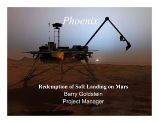
2. Phoenix Was Conceived to Respond
to the Discovery by Odyssey in 2003
A Large Body of Ice Water at the Poles
3. The Big Questions
What happened to the Martian
water?
Phoenix will be the first mission to
touch and examine water on Mars
Is there biological potential at the
northern polar region of Mars?
Three components necessary:
Water Did the ice melt?
Food Nutrients and organics
Energy Solar or chemical
Do the poles indicate global
climate change?
Global climate change is Ancient Mars?
dominated by polar processes
4. Phoenix Landing Site Is Much Farther North
Relative to the Other Landers
-8 -4 0 4 8 12 km
60˚
Phoenix
VL2
30˚
VL1 MPF
Latitude
0˚
Spirit
Opportunity
-30˚
-60˚
180˚ 210˚ 240˚ 270˚ 300˚ 330˚ 0˚ 30˚ 60˚ 90˚ 120˚ 150˚ 180˚
East Longitude
5. Phoenix
(68°N 233°E)
Phoenix Landing Site Latitude and Longitude
If It Were on Earth
10. • 24 hours out the S/C is traveling at speed
of 6,100 mph relative to Mars. During the EDL:
course of the day, the speed steadily
increases An Intense
Seven Minutes
• Deep inside the Mars gravity well, in the
last two hours before entry, speed zooms
to ~12,600 mph!!
• Entry is an altitude of ~130 km (80 miles)
above the surface.
• Mass at entry is slightly over 600 kg.
(1,320 lbs)
• During the eventful/fateful next seven
minutes, the EDL system must take four
zeros off the vehicle speed to prevent
an interplanetary train wreck
11. Heat Shield Parachute
The Ultimate Brake System
Thrusters Landing Legs
12. Phoenix Project FRB/RTF Matrix
Issue MPLF ‘01 Comments Issue MPLF ‘01 Comments
RB RTF RB RTF
A Continuous Communications During EDL 1 1 EDL Communications is baseline. K Fix Known Software Problems 13 Completed. Active SPR process in place.
B Add LGA Transmit Antenna (Landed Ops) 2 2 Originally in baseline, removed after significant study L Fix Post-Landing Fault Recovery 14 15 MSP01 fixed these items per SPR FS1898 and FS1886.
(Feb. 2005). Algorithm/Sequences
C Ionization Breakdown Tests of MGA / UHF in landed 6 Torr 3 Performed UHF breakdown tests. M Validate Lander CG Properties, Ensure Tight 15 13 Significant wet and dry spin testing verified CG properties.
Environment Constraints on Mass Properties to Meet CG
Offset Requirements
D Conduct End-To-End UHF Verification: to 01 Orbiter and MGS 4 Tests were conducted with ODY and MRO test sets. In
addition, MER as a surrogate using CE-505 ran tests with N Beef Up Propulsion Line Support Structure 16 Support structure beefed up as part of '01 baseline. Additional modifications
MRO and ODY identified and implemented after HFTB.
E Satisfactory Propulsion H/W Temps; A. tank outlet & line temps 5,6,7 Propulsion changes already incorporated into '01 design O Perform Heatshield ATLO system first-motion 17 Two separation tests were conducted during ATLO.
above hydrazine freeze point, B. ensure acceptable op temps for via RRSs. Additional mitigations include venting of tank
Separation Test
thruster inlet manifolds & catalyst beds, C. monitor propellant valve pressuring after landing in case of freeze / thaw concern.
temps during flight. P Ensure Thorough Analysis, Simulation, & Test 18 HFTB, ETL, Flight Software into POST
the control system has adequate authority &
F Limit Propellant Migration between tanks to maintain acceptable 8 13 Implemented latch valve isolation to assure no migration stability Margins
levels during All Mission Phases issues.
Q Resolve Small Forces Discrepancies 19 8, 10 Additional calibrations & Delta DOR is documented in Mission Plan and BRM.
G Perform a high fidelity closed Loop Hot Fire Test of Prop System 9 19 Successful HFTB completed. Models verified. Thorough thruster calibration program has been conducted during cruise.
with at least 3 live engines and flight like plumbing support
structure. R Improve TCM 5 Flexibility for improved 20 Mission Design supports flexibility within landing region. End game strategy for
H Evaluate Water hammer Effect on thrusters, structures, and 10 19 Water hammer tests completed. Models verified. landing site control Phoenix significantly robust with full landing site imaging.
controls due to 100% Duty Cycle Thrusters S Modify Radar to Reduce Sensitivity to Slopes 21 16 Upgraded Radar has been developed and extensive EDL tiger team effort retired
all know risks buttressed with thorough test program.
I Conduct Plume-Soil Interaction Analysis or Test 11 26 Completed and incorporated into all analysis.
T Review Key EDL Triggers to Improve 22 15 Conducted EDL subphase reviews focusing on triggers. Modified parachute and
J Ensure compliance with FSW Review and Test Procedures 12 Already part of '01 baseline. Documented in MSP01 Robustness touchdown triggers to improve robustness.
Software Development Plan.
Issue MPL ‘01 Comments Issue MPLF ‘01 Comments
FRB RTF RB RTF
U Confirm Acceptable Probability of Chute 23 Implemented Backshell Avoidance Maneuver (BAM) ZF Implement Active Hazard Avoidance 14 Evaluation of complexity risk vs. landing site risk resulted in not
Draping over Lander including in baseline. Mitigated, to some extent, with the
extensive coverage of our landing ellipse by HiRISE
V Redesign EDL Terminal Descent Nav Filters 3 Accomplished as a result of radar performance Tiger Team effort
ZG Combined with S N/A
W LGA 4 Pi Steradian X-Band Transmit 4 LGA part of the baseline. ZH Formal FSW IV&V 17 West Virginia IV&V engaged
Capability in Cruise
ZI Combined with O N/A
X Steerable X-Band MGA for Surface 5 Originally in baseline, removed after significant study Feb. 2005. (Same as item
Operations B) ZJ Combined with H & G N/A
Y Heaters for IMU to Allow Gyrocompass 6 Deletion of steerable X-Band has removed gyrocompassing from list of mission ZK Ensure RF Compatibility between Radar and EDL 20 Individual component EMI tests conducted, system level test was
Repeat critical functions. Now is info only. (Related to item B) Comm System also conducted and passed.
Z Heaters for PIU to Eliminate Time Constraint 7 Added heaters to work this issue. Eliminated potential flaw in MFB ZL Add flight data recorder (black box) 21 Intent covered by EDL comm.
on Landed Deployments architecture
ZM Improve Robustness in Gyrocompassing/ Lander 22 Deletion of steerable X-Band has removed gyrocompassing from
ZA Combined with Q N/A Attitude Determination Algorithm list of mission critical functions. Now is info only. (Related to
item B)
ZB Rework TLM SW to Provide Detailed 9 Rejected; MPL & ODY showed current system is sufficient, payload needs are
Channelized Instrument TLM. being met. Not related to EDL success. ZN Improve Operability of STL via Checkpoint Restart 23 ODY showed current system is sufficient.
ZC Fix Star Camera Stray Light Issue 11 Baseline is different Star Tracker. Same as MRO
ZO Replace Command / Seq / Block / Config File FSW 24 ODY showed current system is sufficient. S/W style concern.
ZD New Aeromaneuvering Technology for ‘01 12 Aeromaneuvering no longer part of design. Landing site does not require it.
Architecture w/ Command / Seq / Parameter Visible to
Ground
ZE Combined with M N/A
ZP Reduce Separation Guide Rail Snags 25 '01 baseline has no guide rails. Analysis shows robust margins.
Comply Addressed though separate study
13. EDL Teaming Activities Will Utilizes the
Skeptics Strengths of Each Organization Zealots
JPL System Charter for Phoenix EDL: LMA System Requirement for Phoenix EDL:
Maintain ownership and responsibility for EDL success. Design, Build, Test and Deliver a Reliable EDL Flight System.
Own Level-2 Requirements Share Level-3 Requirements Own Level-4 Requirements
Approve & Own Critical Identify Co-Design EDL Negotiate & Manage
Technical Issue
Coordinate Margins & Technical System Implement Mainline EDL
Trades
V&V Plan Parameters Issues Architecture V&V Plan Delivery
Understand Focus on Focus on Perform I&T Deliver EDL
Define Define Solution
Performance Trajectory & Sequence & of the EDL Flt Subsystem
Problem Space Space
Sensitivity Simulations Constraints System Components
ATLO Software
Plan/Do Perform Approve Implement
Robustness Parametric Solutions or Approved ETL/STL Power
Tests Analysis Changes Solutions
Perform Perform Softsim Avionics
ETL/STL POST Trajectory Trajectory
Analysis Analysis Thermal
Softsim ADAMS
LaRC
Propulsion
V&V Working Perform
Group (SVT) Aerothermal TPS
Develop first order EDL system
Analysis
design understanding
Harness
Integrated EDL System Engineering for Key
Functions and Subsystems Telecom
Negotiated Aerothermal &
Insight & TPS IV&V Mechanical
Oversight Support
G&C
ARC
Badge-less EDL system
team based on mutual
LARC/ARC JPL LMA respect
14. Cruise Stage Separation: 4:24 pm PST
• Seven minutes before entry, the
entry vehicle separates from
the cruise stage
- Twelve pyro firings break up
six separation nuts
Separation Connector Force Margin
• Vehicle power is now supplied
by its internal batteries
Communication now
• Thirty seconds after separation begins with Odyssey
the entry vehicle conducts an and MRO — carrier
autonomous slew to the entry
attitude only for the next five
minutes and then 8
Kb/s two minutes
Cruise Stage Re-contact!
before entry
15. The Hypersonic Phase
• Even though Mars’ atmosphere is
Hypersonic Control thin (1% of Earth), we use it in the
Instability first 4 minutes of entry to dissipate
~94% of the entry vehicle energy
and slow it down from ~13,000 mph
to ~1,100 mph.
• As the vehicle blazes through the
atmosphere, the surface of the heat
shield reaches a peak temperature
of 1,4000C (~ 2,6000F).
16. The Parachute • Still traveling at 1,100 mph but
now only 40,000 feet off the
Parachute Loads surface, a mortar punches
through a plate on the back shell,
deploying a supersonic chute
(Mach 1.5). The timing is
controlled by an IMU with a timer
as a backup.
• Communication rate to Odyssey
and MRO changes to 32 Kb/s.
• It is now ~3 minutes before
landing.
17. Heat Shield Separation
15 seconds after the
chute deployment,
six pyros cut the
heat shield loose
and a strong spring
No Problems! action pushes it
away.
18. Landing Radar
• 10 seconds after heat
Landing Radar
shield jettison, the landing
Perfect for F-16’s:
legs deploy
However……
• At ~3 minutes (160s) before
landing, the landing radar
activates
– Acquires the altitude
information at ~8,000 feet
and three axis Doppler at
~6,000 feet above the
surface
19. Lander Separation
• 37 seconds before landing and at
3,000 feet above the surface, six
pyros ignite three explosive nuts
which release the lander from the
backshell
• The lander is now traveling
approximately 120 mph
• The lander will freefall for 0.5
seconds before the thrusters are
fired
20. • Three seconds after
Pulsed Mode separation, and 34 seconds
before touchdown, twelve 68
Thrusters lb terminal descent thrusters
are initiated
• Critical in this time period is
interaction between the radar
Conducted extensive and the ACS system.
dynamic validation Altitude knowledge error
tests for terminal translate to velocity error
descent!
• Phoenix is the first lander
since Viking to use thrusting
for terminal descent
21. Touchdown Carpeted Landing
Ellipse with high
resolution HiRISE
images!
• Prior to landing, the vehicle ‘pirouettes’ to establish an east/west
orientation of the solar arrays
• The lander achieves a constant velocity of 5 mph at approximately
100 feet from the surface
• The lander detects the ground with any of three touchdown sensors,
terminating the engine thrust
• The legs can compress by 6 inches
• At touchdown, the mass of the vehicle is now 365kg
(approximately 800 pounds)
22. Phoenix Ground Track
Pho
enix “Heimdall”
Gro
und Crater
Tr ac k
R ISE
Hi View
RO era
M m
Ca
27. The Phoenix
Landed Payload Weather and climate
LIDAR MET mast
(Temp/Wind)
CDR 50 Days
ATLO StereoDays
Surface 196 Imager MECA: microscopy, electro-
Ship 596 Days chemistry, conductivity
Launch 675 Days
EDL 971 Days Mineralogy/chemistry
TEGA: Thermal and
Physical geology Evolved
RA Camera Gas Analyzer
Robotic ArmGoldstein – ProjectThermal and Electrical
Barry Manager
Ice tool, scraper blades– Project Business Manager
Glenn Knosp conductivity probe
28. Sol‐0
Solar Array Deployed RA Bio-
Barrier/MET
Mast (deployed)
Horizon
Footpad (very little soil) Postcard
29. Sol‐3
Wrist Deployment
Elbow Deployment
RAC High Above The Deck
Deployment of Robotic Arm
35. Sol‐25
Water Ice
Confirmed!!
Water Ice
Chunks Sublimation of ice
chunks over 4 sol
period consistent with
water at measured
temperatures and
pressures
47. Will Phoenix Have A Mission
Life Like the Rovers?
The Sun low on the polar horizon
PHX Surface Sunlight Duration
25
24
23 CO2 Ice Encasement (2/2/09-11/20/09)
22
21
20
19
18
17
Hrs Sunlight (> 0 deg)
16
15
14
13
12
11
10
180 Solar Conjunction (11/18/08-
9
8
7
6
5
4
3
12/24/08)
2
1
0
0
30
60
90
120
150
210
240
270
300
330
360
390
420
450
480
510
540
570
600
630
660
690
720
750
780
810
840
870
900
930
960
990
1020
Sol
May 25, 2008
Nov. 18, 2008 April. 1, 2009
48. Why not airbags?
MER Phoenix
Athena
Payload 21 Kg Science Phoenix
Payload
60 Kg
Payload
60 Kg
223 Kg
(Rvr 173))
Effective Landed
Mass
Rover &
Egress
Equipment
310 Kg
Air Bag
309 Kg
System,
Lander
Touchdown Legs &
Prop
Components 57 Kg System
Total Landed
Mass
532 Kg