Poster svalbard 2007
•
1 like•532 views

Subglacial drainage in porous aquifer and sediment consolidation patterns in the glaciated valley of Andorra (Pyrenees). The poster was presented for the IAG/AIG (International Association of Geomorphologists) Regional Conference on Geomorphology Geodiversity of polar landforms which was held in Longyearbyen (Spitsbergen, Norway) on August 1-5, 2007. Conference was organised on the occasion of the International Polar Year 2007/2008 by the Association of Polish Geomorphologists.
Recommended

Recommended
More Related Content
What's hot
What's hot (20)
Viewers also liked
Viewers also liked (7)
Similar to Poster svalbard 2007
Similar to Poster svalbard 2007 (20)
More from Fundació Marcel Chevalier
More from Fundació Marcel Chevalier (20)
Poster svalbard 2007
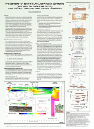
- 1. 1 2 3 4 5 6 87 3 6 1 0 Lateral Esker Depth(m) 9 10 PRESSUREMETER TEST IN GLACIATED VALLEY SEDIMENTS (ANDORRA, SOUTHERN PYRENEES): FOSSIL SUBGLACIAL DRAINAGE PATTERNS, DYNAMICS AND RHEOLOGY TURU, Valenti* Igeotest SL (Marcel Chevalier Foundation Project), Dptx 408, Av. Príncep Benlloch 66-72, AD-500, Andorra la Vella. Principality of Andorra (Europe) At the Upper Peistocene in Andorra, as the almost glacial valleys, several glacial tongues join to form a significant accumulation of ice at the end of their trajectory, in the ablation zone. Meltwaters generally follow various paths until arriving at the snout, but significant amount enters through glacier crevasses and moulins as well as through lateral moraines, until saturating the subglacial aquifer (MENZIES, 1995). Eventually poor drainage of the system may accumulate water under the ice until a certain piezometrical height resulting from the balance between ice fusion and water drainage. If the glaciostatic pressure is exceeded the glacier follows the Archimede’s law, basal contact is lost and a surge event can be produced (NIELSEN, 1969). Once subglacial drainage is again established efficiently, by one or several subglacial tunnels (see i.e. BOULTON et al., 2001), the entire system is conditioned. In this sense, pre-existing morphologies may condition the position of these channels or tunnels beneath the glacier (MENZIES, 1995), such as subglacial gorges or the confluence of glacial tongues. Subglacial gorges constitute entryways for subglacial water from tributary valleys, while confluence between glaciers constitutes a lineal anisotropy from which, if conditions are favourable, a subglacial drainage tunnel may be formed. This is the case that appears to have occurred in the Andorra valley. Following a profile parallel to the main axis of the valley, overconsolidation has been observed to increase upstream (TURU et al. 2007), that mean that the effective pressures where greater upstream rather than on the snout zone. That can be easily explained because upstream the glacier thickness is greater rather than in the snout zone, also greater meltwater is present at the ablation zone near to the snout for temperate glaciers. The magnitude of the preconsolidations observed in Andorra should be taken as an indicative value of ancient effective pressure beneath the andorran valley glacier. The value of these preconsolidations are compatible with the presence of R and C subglacial drainage channels beneath the valley glacier (MENZIES, 1995). Following a profile perpendicular to the main axis of the Andorra valley, overconsolidation pressure has been observed to vary, being greater in the centre, so in ancient times effective pressures where greater in the mean valley, and a major tunnel or drainage channel might existed there. Stress/strain data obtained in pressuremeter tests not only have been observed to vary regarding the location in the glaciated valley, but also in depth at the valley floor. As noticed in TURU (2007) stress/strain evolution named Type 1, Type 2 and Type 3 diagrams are observed in Andorra and discussed here taking into account their geological setting. Introduction Stratigraphical architecture of the glaciated valley Geoelectrical survey data represented in a transverse profile to the main axis of the Valley (figure 1a) shows a symmetrical distribution of electrical resistivity. The resistivity symmetry consists of the existence of three highly resistive cores, two of which are located in the sides of the valley and one in the centre. The position of the lateral high resistive bodies coincides with the position of the subglacial gorges of the tributary valleys, while the resistive body located in the centre of the valley coincides with the position of the confluence of the two largest glaciers. Between them low resistivity sediments are present. The group is stratified showing almost five geoelectrical units and are interpret as sedimentary starts. On the other hand, has been empirically determined in Andorra that there is a strong relationship between fine grain content (grains less than 0.08 mm in size) and the resistivity (figure 1b). It has also been observed that lateral high resistive bodies are primarily formed by boulders, while no boulders have been detected by bore-holes in the central resistive body. The origin of the boulders must be attributed to lateral moraine erosion and to sedimentary contribution channelled by subglacial gorges. From these descriptions, those high resistive lateral cores could by assimilate into eskers. The high resistivity results from the scarcity of fine grains (< 0.08 %) due to a cleaning of the matrix produced by significant channelled subglacial water flows (R or C channels, or tunnels). Rehological architecture of the glaciated valley The rheology of the sediments are related with its stress/strain behaviour. From parallel communication it is known that from pressuremeter diagrams rehological behaviour from tested soils are obtained. In that sense if we plot the most representative diagrams on the resistivity profile (figure 1c) some conclusions can be done: 1) Type 1 diagrams are mostly located in the less resistive layers 2) Type 3 diagrams exclusively are located in the resistive bodies 3) Type 2 diagrams are widespread located, close to the others Sediments showing Type 1 diagrams will present an elasto-plastic stress/strain behaviour (see figure 1c). The sediments with Type 3 diagrams are restricted to the high resistivity core at the mean valley; hyperelastic behaviour for small strains (seismic waves) is expected, hypoplastic behaviour for larger strains is also expected, and finally for very large strains a failure criterion can be obtained. Between them Type 2 diagrams domain, with sediment showing continuous stress/strain memory until hyperplastic yield is exceed, then a classical plastic behaviour is expected. TURU (2007) Typer 2 diagrams, which are quite widespread in the glaciated valley, are related with ancient subglacial load and unload (L-UL) cycles related with ancient subglacial drainage. Subglacial drainage pathways of the glaciated valley It is also acknowledged in the literature (BOULTON & ZATSEPIN, 2001) that the glacial ablation process is not continuous through time and is subject to seasonal, daily and climatic cycles. Thus the subglacial sediments have been subjected to various load and unload (L-UL) cycles and generated the consolidation of subglacial materials. In Andorra Type 2 diagrams will show us the sites where the L-UL cycles have been recorded. Type 2 diagrams present more stiffness with depth but also laterally close to the high resistivity bodies. Also Type 2 diagrams present less stiffness in the low resistivity bodies, there where sediments with Type 1 diagrams also exist. Two main subglacial drainage pathways can be distinguished regarding its valley position. Drainage in the central part of the valley Type 3 diagrams are the stiffest one, only present at the high resistivity body in the mean valley, and its presence is related with the most important piezometric drop in the glaciated valley (figure 2a-c). In that sense the resistivity data and the stress/strain data show us roughly an important drainage flowpath in the mean valley for the ancient subglacial aquifer. Drainage in the lateral part of the valley In essence, lateral eskers would basically correspond to zones of meltwater entry in the subglacial system, with the water being drained out of the system by the underlying granular aquifer as well as by the central tunnel (figure 2a-c). The stratification observed in the valley by geophysical data clearly show a sedimentary accretion, closely related to the drainage process beneath the ancient glacier. The subglacial sedimentary accretion can be interpreted as a constructional process (HART & BOULTON, 1991) and some consequences of that architecture in the subglacial dynamics are expected: a) Abandoned eskers went no more directly connected with the lateral valleys drainage, but is expected that they could act as pipe conduits keeping hydraulically connected distant subglacial regions with different water levels. b) Subglacial sedimentary accretion implies that the deepest layers have been subjected to more hydraulic cycles than the shallow ones. Also the layers close to the principal drainage pathways (central tunnel and the lateral eskers). Valley glacier subglacial drainage pathways From outcrops, bore-holes sedimentological data, and pressuremeter tests point out that, at the high resistive cores strata accretion is also present. Layers showing light stiffness Type 2 diagrams were detected in silty-gravely layers. In the high resistivity cores these layers have less thickness than the layers showing heavy stiffness, while at the low resistivity bodies these layers have greater thickness than the stiffen Type 2 diagrams. The presence of these layers showing small stiffness, lightly consolidated, below layers with great stiffness (heavily consolidated), was firstly indicate and explained by TURU (2000) in Andorra (figure 2 d-f). At the mean valley both layers are always present together, named as “bicouches” by TURU et al. (2007). The heavily consolidated layer and the lightly consolidated layer from theses “bicouches” were named as “a” and “b” respectively by TURU (2000) and it’s geometry across the valley has be studied by TURU et al. (2007). Type “b” layers were of great significance for the aquifer drainage, acting as a important drainway for the ancient subglacial system, so was not possible for those layers to consolidate further. Since that kind of layers are present in the aquifer, many of the drainage might go through keeping hydraulically connected the central tunnel and the lateral eskers. Taking into account these particularities and the general behaviour of the subglacial drainage, the ancient flowpaths in the glaciated valley aquifer are drawn (figure 1d). Subglacial dynamics of the glaciated valley Subglacial pervasive shear stress should be also archived in the subglacial sediments, there where water pore pressures were low, specially at the mean valley where the central tunnel was present. Subglacial coupling might happen at the mean valley position, at the same places where pervasive shearing was greater and best transmitted. Should be noted that only the materials present at the mean valley show hyperelastic and hypoplastic behaviours for small and large strains respectively. Those materials show Type 3 diagrams and are the most consolidated in the valley. Dense packing of the porous skeleton (TURU, 2000) was expected for that kind of terrain. It is known from the literature (MENZIES, 1995; EVANS et al. 2006) that an efficient glacier coupling leads ploughing over unconsolidated sediments. In Andorra the ancient glacier might not have an efficient coupling at those strata showing Type 1 diagrams or lightly consolidated Type 2 diagrams, but coupling might be largely done at the mean valley position where heavily consolidated materials are present. Is expected that ploughing happen at the beginning of the consolidation process but might diminish for further consolidation. If we take into account the “bicouche” structure of the strata from the ancient subglacial aquifer, pervasive shearing might not being transmitted to further depth, because the “b” type layer of the “bicouche” will significant reduce the pervasive shear stress transfer to further depth by its weakness, but ploughing of the whole “bicouche” could happen and substantial pile-up of “bicouche” can result (see TURU et al. 2007). That pile-up only could happen at the mean valley subglacial floor, there where was the subglacial tunnel. If the amass entails a drainage decrease in the tunnel, subglacial water pressure could grow submitting the glacier in a flotation condition toward a decoupling from its bed. Subglacial sedimentation can then happen and subaquaceus facies can be deposited (specially turbidites), as is explained by BRENNAND (2000) for subglacial meltwater drainage. When subglacial drainage becomes again efficient enough to permit a new coupling between the glacier and its bed, the new subglacial sediment undergo to consolidate following the Type 1, Type 2 and eventually Type 3 stress/strain behaviours and a new “bicouche” is formed. Tunnel subglacial drainage did permit the glacier weight transmission to the mean valley floor, while at the lateral valley floor low subglacial effective pressures were present. These stress patterns at the valley floor could derive to an overload faulting following the suhoritzontal structure of the “bicouches”, similar happen to shallow foundations when the bearing capacity is exceeded. Here hyperelastic and hypoplastic terrain will act as a shallow foundation, the glacier weight as the load, and the elasto-plastic & light stiffen hyperplastic materials (the “b” layer of a “bicouche”) could only impose a low bearing capacity, so a pile-up is expected at the valley sides by the penetration keel of hyperelatic-hypoplastic (HEHoP) material under the glacier (figure 2g). It is noted here that if HEHoP keel produce further penetration ancient sediments will be preserved at the valley sides and it has been observed in Andorra by TURU et al. (2007) but also in many valley glaciers in the Alps (NICOUD, et al. 2002). Conclusions Any subglacial sediment subjected to drainage with load and unload hydrological cycles should present consolidation patters similar to those here described. Without the use of pressuremeter tests might be impossible to obtain a significant number of strain/stress data to permit the rheology study of glacial sediments at Andorra. However similar rehological behaviours to those of type 2 curves have been obtained from oedometric tests, but the lack of data inherent to the granulometry of the glaciated sediments did not permit to get further data by that way. Without representative data of the whole family of subglacial sediments (EVANS et al., 2006) the rheological study of them is almost impossible, but much research is still needed to be able to completely explain the rheological characteristics of subglacial sediments, specially comparative studies all over the glaciated areas. TURU, V., BOULTON, G.S; ROS, X.; PEÑA-MONNÉ, J.LL.; MARTÍ-BONO C.; BORDONAU, J.; SERRANO-CAÑADAS, E.; SANCHO-MARCÉN, C.; CONSTANTE-ORRIOS, C.; POUS, J.; GONZÁLEZ-TRUEBA, J.J.; PALOMAR, J.; HERRERO, R. & GARCÍA-RUÍZ, J.M. (2007). “Structure des grands bassins glaciaires dans le nord de la péninsule ibérique: comparaison entre les vallées d’Andorre (Pyrénées Orientales), du Gállego (Pyrénées Centrales) et du Trueba (Chaîne Cantabrique)”; Quaternaire, Nº 3-4 (in press). TURU, V. (2000) “Aplicación de diferentes técnicas geofísicas y geomecánicas para el diseño de una prospección hidrogeológica de la cubeta de Andorra, (Pirineo Oriental): implicaciones paleohidrogeológicas en el contexto glacial andorrano”; In: Actualidad de las técnicas geofísicas aplicadas en hidrogeologia, ITGE -IGME (Ed.), Madrid, 203-210. (http://aguas.igme.es/igme/publica/pdfactu_tec_geofi/14a_comunicacion.pdf) MENZIES, J. (1995)Hydrology of glaciers; In: Modern glacial environments: Processes, Dynamics and Sediments, Jhon MENZIES (Ed.),197-239 BOULTON, G.S.; ZATSEPIN, S. & MAILLOT, B. (2001) “Analysis of groundwater flow beneath ice sheets”; TR-01-06 technical report of the Swedish Nuclear Fuel and Waste Management Co. (SKB), Stockholm, 53pp NIELSEN, L.E. (1969) “The ice-dam, power flow theory of glaciers surges”; Canadian Journal of Earth Sciences, Vol. 6., 955-959 TURU, V. (2007) Pressuremeter test in glaciated valley sediments (Andorra, Southern Pyrenees), Part One: An improved approach to their geomechanical behaviour; Landform Analysis (in press). HART, J. K. & BOULTON, G. S. (1991) “The interrelationship between glaciotectonic deformation and glaciodeposition within the glacial environment”, Quaternary Science Reviews, 10, 335-350 BRENNAND, T.A. (2000) “Deglacial meltwater drainage and glaciodynamics: inferences from Laurentide eskers, Canada”; Geomorphology, 32 (3-4), 263-293 EVANS, D.J.A.; PHILLIPS, E.R.; HIEMSTRA, J.F. & AUTON, C.A. (2006) “Subglacial till: formation, sedimentary characteristics and classification”; Earth-Science Reviews, 78, 115-176 FIGURE 1 Literature FIGURE2 in in out out out > 6.7 MPa > 4.7 MPa 2.9 MPa 0.15 MPa 0.15 MPa 0.13 MPa 0.26 MPa 0.49 MPa 0.58 MPa 0.99 MPa Pf(S3) Pf(S2) 0.13 M Pa 0.21 M Pa Pf(S1) P waves Pwaves Mean Valley TunnelEastern Lateral Esker Western Lateral Esker Apparent resistivity (Ohms x m) Horizontal distance (m) AB/2depth(m) Eastern lateral esker 680 m/s 879 m/s 1252 m/s 606 m/s 3100 m/s 1174-977 m/s 0 5 10 15 3 6 10 0 Water pressure = Sediment weight + Ice weight LATERAL POSITION WITH REGARD TO THE TUNNEL, B Lines join together Glacier flotation condition at the lateal of the tunnel 0 5 1 1 0 1) Gravitational weight of sediment 2) Dynamic water pressure 3) Gravitational weight of ice CENTRAL POSITION TO THE TUNEL, A 3 6 10 Both lines can not join, no flotation exist beneath the drainage tunnel 1 2 3 4 5 6 8 9 1 07 3 6 1 0 Lateral Tunnel -+ Esker - - + - Tunnel Snout Glacier valley H2O Moulins Crevasses Equipotentials Flow lines Aquifer Tunnel R Lateral esker (b) Static water table Dynamic water table Supposed glacier height 100 m Depth (m) 0 3 6 10 BA (c) 11 10 9 8 7 6 5 4 3 Valley wall (g) EskerTunnel a b cd abcd a b cd a bc a b a Glacier Load Extension Horizontal displacement Keel Half hat shape esker Compression Prandtl logaritmic loop Penetration Keel Acknowledgements Thank you to Andrzej Niemunis for its comments, and I wish dedicate to Geoffrey Boulton this paper; here are reflected more than seven years of discussions in a good company at Andorra and Edinburgh. Many thanks. Bobachev,A.A;Shevnin,V.A.&Modin,I.N.2003-IPI2WINversion3.0.1e; http://www.geol.msu.ru/deps/geophys/rec-lab3.htm 6050403020100 0 200 400 600 800 1000 Andorra glaciated valley Granulometric % of Silt and Clays (<0,08 mm) OhmsXm y = 699.77 + -315.74*LOG(x) R^2 = 0.412 Correspondence between electrical resistivity and fine grained content Depth(m) 1 + 3 Effective pressure: 1 + 3 - 2 Pressure (100 x KPa) (e) (d) Depth(m) Pressure (100 x KPa) effective pressure 1 3 2 1+3 1 effective pressure 2 3 1+3 (f) Effective pressures (100xKPa) (a) (b) (a) (c)(d) Flowpaths Esker Esker Tunnel Elasto-plastic Hyperplastic Hyperelastic Hypoplastic Yield pressures V.Turu (2007) Substratum VES 1 march 1993 Colluvium Esker -SEV3 -SEV1 -SEV2 -SEV4 -SEV4b -SEV2b 20 m - 40 m - 60 m - 80 m - 100 m - 120 m - 140 m - 160 m - 0 m 20 m 40 m 60 m 80 m 100 m 120 m 140 m 160 m 180 m 200 m 220 m 240 m 260 m 280 m 300 m 320 m 340 m 360 m 380 m 400 m 420 m -126 -158 -200 -251 -316 -398 -501 -631 -794 2b1b 2 1a 2a 1a 1 2 3 3 4 5 1b 1 ? 3b 876543210 0 50 100 150 200 250 Type 1 diagram Stress (x 100 KPa) Elasto-Plastic Yield point (Po') Strain(volumecm3) (c)Stress (x 100 KPa) 1514131211109876543210 0 100 200 300 400 500 600 700 800 FEDA ERT S4-P3 (-3,4 m) Po' (1) Po' (2) Po' (3) Po' (4) Type 2 diagram Strain(volumecm3) Load-Unload cycles Po' (3) Po' (1) Po' (2) Po' (4) Hyperplasticity external Yield surface (Y3) 706050403020100 100 200 300 400 500 600 La Closa S3b-P3 (-21,6 m) Stress (x 100 KPa) Strain(Volumecm3) Type 3 diagram No external yield surface is reached