
Recommended
More Related Content
Recently uploaded
Recently uploaded (20)
Featured
Featured (20)
Hioki 3174 Insulation Tester
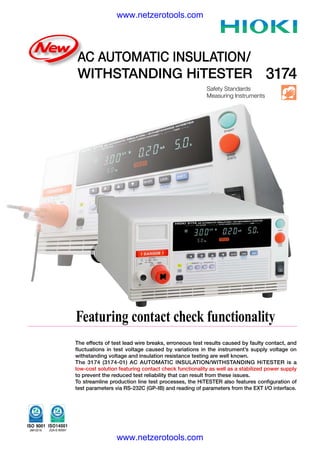
- 1. www.netzerotools.com AC AUTOMATIC INSULATION/ WITHSTANDING HiTESTER 3174 Safety Standards Measuring Instruments Hioki 3174-01 AC Automatic Insulation Withstanding HiTester Featuring contact check functionality The effects of test lead wire breaks, erroneous test results caused by faulty contact, and fluctuations in test voltage caused by variations in the instrument’s supply voltage on withstanding voltage and insulation resistance testing are well known. The 3174 (3174-01) AC AUTOMATIC INSULATION/WITHSTANDING HiTESTER is a low-cost solution featuring contact check functionality as well as a stabilized power supply to prevent the reduced test reliability that can result from these issues. To streamline production line test processes, the HiTESTER also features configuration of test parameters via RS-232C (GP-IB) and reading of parameters from the EXT I/O interface. www.netzerotools.com
- 2. 2 2 www.netzerotools.com Improved Test Reliability NEW ● Contact check function improves test reliability If a test lead wire were to break during testing with The 3174’s contact check function lets you detect test lead a tester that does not offer wire breaks and faulty contact during testing by sensing contact check functionality, defective test pieces would be measurement issues in real time. judged to be non-defective. Withstanding voltage tester Withstanding voltage tester The 3174 improves test reliability by monitoring Voltage output Faulty contact Voltage output voltage to detect lose *Break in lead leads during testing Voltage monitor Voltage monitor and faulty wiring during measurement. Voltmeter Voltmeter Contact check Contact check *Since contact check is performed Test current while testing is in progress, use of Test current contact check functionality does Test piece not increase cycle time. Test piece Faulty contact If a test lead were to come lose *Disconnected lead during testing with a measurement device that does not offer contact check Fluorescent display tube functionality, defective test pieces The display uses a bright, would be judged to be non-defective. easy-to-read fluorescent tube. DANGER lamp Flashes a warning during testing and whenever high voltage is present at the terminals. The DANGER lamp turns off when the voltage at the output terminals is no greater than AC 30 V or DC 60 V. 9613 9614 SINGLE-HAND TWO-HAND REMOTE CONTROL REMOTE CONTROL (option) (option) External switch Test mode selection Enables start/stop control by means of Select from three test modes: the 9613 SINGLE-HAND REMOTE 1.Manual test mode: W (withstand voltage testing) / I (insulation resistance testing) CONTROL or 9614 TWO-HAND 2.Automatic test mode: W→I / I→W REMOTE CONTROL. (The 9613 and 9614 are optional.) NEW ● Judgment output at forced stop ● Ramp timer function The ramp-up initial value, ramp-up and ramp-down time The ability to obtain a judgment even after a forced stop increases testing freedom. parameters can be set independently. ● True effective value display NEW ● Eliminate the effects of supply voltage fluctuations ● Continued analytical testing after FAIL judgments ● Delay timer function Test pieces can now be analyzed by means of detailed monitoring of the test current accompanying FAIL judgments. www.netzerotools.com
- 3. www.netzerotools.com 3 3 Safe, Automated Operation Convenient Safe ● Continuous full-auto withstanding voltage and insulation resistance testing ● Interlock function The 3174 lets you set independent test conditions including Signal input from an external device such as an automatic test voltage for withstanding voltage and insulation tester can be used to disable output and prevent testing, resistance testing, and you can perform these tests ensuring safety during automatic testing and other uses. continuously. Press the W→I key to automatically perform withstanding voltage followed by insulation resistance tests, or press the I→W key to automatically perform insulation resistance followed by withstanding voltage tests. GP-IB (option) Enables remote control. RS-232C Enables remote control. Contact check LOW: A break in the lead is determined to have occurred when the check current is not detected. HIGH: A break in the lead is determined to have occurred when the contact check Power cord inlet measurement voltage falls outside the range defined by the upper and lower thresholds. (Connectors are locked in place as shown on the left to prevent the leads from being disconnected.) *Requires an additional pair of 9615 HIGH-VOLTAGE TEST LEADS. Rear panel voltage output terminals The rear panel terminals are connected at all times to the front terminals. When Status out relay terminals embedding the 3174 HiTESTER inside Maximum input voltage: AC 150 V, DC 30 V an automatic tester, connections can be Maximum contact current: 0.5 A made via the rear panel terminals. An OR operation applied to various enabled conditions 9616 WARNING LAMP determines whether relay terminal output is turned on. Devices (option) Buzzer volume knobs such as the 9616 WARNING LAMP can be connected. (AC100V,0.1A) The 3174 provides separate 1. H.V.ON Output voltage generation volume adjustments for the PASS 2. TEST Testing in progress and FAIL judgment buzzers. 3. PASS PASS state (Includes warning lamp unit only. 4. FAIL FAIL state Refer to the included plans and drill 5. INT.LOCK Interlocked state installation holes in a base such as a 6. READY Ready state metal plate as necessary.) 7. EXT.CONT. Under external control 8. POWER.ON When the 3174 is on External I/O connector (Signal lines have photocoupler isolation.) Pin I/O Signa Function ■ Interface specifications 1 OUT READY Low in ready state E X T I / O : Output signals 2 OUT L-FAIL Low in FAIL state (lower bound) Open collector output (with photocoupler isolation) 3 OUT U-FAIL Low in FAIL state (upper bound) All active low with a maximum load voltage of DC 30 V 4 OUT PASS Low in PASS state Maximum output current: DC 100 mA per signal 5 OUT TEST Low in test sate Output saturation voltage: DC 1.5 V or less 6 OUT H.V.ON Low when voltage is present at output terminals Input signals 7 IN EXT-E When low, external I/O input signals are enabled All active low input (with photocoupler isolation) 8 IN START When low, same function as START key Maximum applied voltage: 30 V 9 IN STOP When low, same function as STOP key High level voltage: from DC 15 V to 30 V, or open 10 IN INT.LOCK Interlock on open Low level voltage: DC 5 V or less (-6 mA typ.) 11 OUT W-MODE Low during withstanding voltage testing 12 OUT I-MODE Low during insulation resistance testing EXT SW : Input signals (contact input) 13 OUT W-FAIL Low in FAIL state during withstand voltage testing START, STOP, SW.EN (external switch terminal enable) 14 OUT I-FAIL Low in FAIL state during insulation resistance testing 15-18 IN ISO.COM Ground inputs for external devices Output signals 22-25 IN MEM-0 to 3 Saved test selected pins LED activation signal (maximum load current: 40 mA) 27 IN MEM-E When low, enables memory selected pins 28-29 OUT MODE-0,1 Current test mode 33-36 OUT ISO.DCV Internal DC 15 V power supply (100 mA) www.netzerotools.com
- 4. www.netzerotools.com Withstanding Voltage Testing Timers Test Voltage Setting range : 0.3 to 999 s Output voltage : AC 0.2 to 5 kV (50/60 Hz), single-range output Operation : When set to on: Display counts down from the set time after start. When set to off: Display indicates time elapsed since start. Voltage output method : PWM switching method (0 V start; voltage can be Setting resolution/accuracy : 0.1 s (0.3 to 99.9 s) ±50 ms changed while generating output) 1 s (100 to 999 s) ±0.5 s Voltage specification method : Digital (setting resolution: 0.01 kV) Ramp Timers (Withstand voltage testing) Output voltage accuracy : ±1.5% of setting ±20 V Setting range : 0.1 to 99.9 s: Ramp-up and ramp-down can be set independently. Maximum rated output : AC 100 VA (5 kV/20 mA) continuous rating Operation : Ramp-up: The output voltage increases linearly from the Transformer capacity : 100VA initial voltage to the test voltage over the ramp-up time. Ramp-down: The output voltage decreases from the set Voltmeter : True effective value display voltage to 0 V over the ramp-down time after the test time Digital meter: AC 0 kV to 5.00 kV elapses, and the display counts down from the set time. Accuracy: ±1.5% rdg (1,000 V or less, ±15 V) *The actual ramp-up waveform varies with the load due to the analog response delay. Output waveform : Sine wave Setting resolution : 0.1s Voltage change rate : 15% or less (converges to setting within 1 s during Delay Timers (Insulation resistance testing) change from maximum rated load to no load) Setting range : 0.1 to 99.9 s Distortion factor : 5% or less (tester impedance during measurement with 5 Setting resolution : 0.1s kV output under 40 MΩ load) Frequency : 50/60Hz (±0.2%) Decision Function Current Detection Decision method : Window comparison method with upper and lower bound settings (digital specification) Current measurement range : 0.01 mA to 20 mA (2 ranges) Decision results : UPPER-FAIL: The measured current (measured insulation value) exceeded the specified upper threshold. Measurement range : 10mA/20mA PASS: The measured current (measured insulation value) fell within Indicated value : True effective value display the range defined by the specified upper and lower thresholds. Measurement ranges and : 0.00 mA to 10.00 mA, 0.01 mA (10 mA range) LOWER-FAIL: The measured current (measured insulation value) was less than the specified lower bound. resolutions 0.0 mA to 20.0 mA, 0.1 mA (20 mA range) UPPER LOWER-FAIL: A testing error occurred, for Measurement accuracy : ±2% rdg ±0.05 mA (10 mA range) example due to a failure to generate the set voltage. ±2% rdg ±0.5 mA (20 mA range) Decision processing : Display, buzzer, and EXT I/O signal output is generated according to each decision result. Setting range : AC withstanding voltage: 0.1 to 20.0 mA (upper threshold), 0.1 to 19.9 mA (lower threshold) DC insulation: 0.2 to 2,000 MΩ (500 V) or 1.0 to 2,000 MΩ (1,000 V) for both upper and lower thresholds Insulation Resistance Measurement Setting resolution : AC withstanding voltage: 0.1 mA Test Voltage DC insulation: 0.01 MΩ (0.2 to 2.00 MΩ), 0.1 MΩ (2.10 to 20.0 MΩ), 1 MΩ (21.0 to 200 MΩ), 10 MΩ (210 to 2,000 MΩ) Rated voltage : DC 500 V/1,000 V (positive polarity) Unloaded voltage : 1 to 1.2 times rated voltage Rated measurement current : 1 to 1.2 mA Contact Check Voltmeter accuracy : Detection method: Average value detection/effective value conversion Short-circuit current : 4 to 5 mA (500 V), 2 to 3 mA (1,000 V) Accuracy: Setting ±50 V *Inaccuracy may increase when the waveform is distorted. Measurement range 0.2 to 2,000 MΩ (500 V), 0.5 to 2,000 MΩ (1,000 V) : Decision results : Enables the contact check function (does not increase cycle time). Guaranteed accuracy 0.5 to 999 MΩ (500 V), 1 MΩ to 999 MΩ (1,000 V): ±4% rdg : LOW: A break in the lead is determined to have occurred when the check current is not detected. ranges/accuracies 1,000 MΩ to 2,000 MΩ: ±8% rdg HIGH: Upper and lower thresholds for the check detection voltage can be set. A Measurement resolution : 0.01 MΩ (0.20 MΩ to 19.9 MΩ) break in the lead is determined to have occurred when the contact check measurement 0.1 MΩ (20.0 MΩ to 199.9 MΩ), 1 MΩ (200 MΩ to 2,000 MΩ) voltage falls outside the range defined by the upper and lower thresholds. Measured resistance ranges : 2 MΩ, 20 MΩ, 200 MΩ, 2,000 MΩ (500 V) Voltage setting range : Withstanding voltage testing: 0.20 kV to 5.0 kV (0.01 kV resolution; applies to both 4 MΩ, 40 MΩ, 400 MΩ, 2,000 MΩ (1,000 V) upper and lower thresholds)Insulation resistance measurement: Upper threshold of 600 V and lower threshold of 500 V (during 500 V measurement); upper threshold of 1,200 V and lower threshold of 1,000 V (during 1,000 V measurement) (both fixed) General Specifications Model Display : Fluorescent display tube (digital display) Monitor functions : Output voltage, detected current, insulation resistance AC AUTOMATIC INSULATION/WITHSTANDING HiTESTER 3174 Monitor period : 2 times per second, minimum AC AUTOMATIC INSULATION/WITHSTANDING HiTESTER 3174-01 (GP-IB Model) Operating temperature range : 0°C to 40°C, 80% RH or less (non-condensing) Storage temperature range : -10°C to 50°C, 90% RH or less (non-condensing) Temperature and humidity : 23 ±5°C, 80% RH or less (non-condensing) Options range for guaranteed accuracy (With warm-up period of at least 10 min) Guaranteed accuracy term : 1 year Operating environment : Indoors at elevations of up to 2,000 m at a pollution level of 2 Supply voltage : AC 100 to 240 V Designed to tolerate voltage fluctuations of ±10% of the rated supply voltage. Power supply frequency : 50Hz/60Hz Withstanding voltage : Power supply to chassis: 1.39 kV at 10 mA for 15 s Maximum rated power : 200VA Dimensions : Approx. 320 (W) × 155 (H) × 395 (D) mm (excluding protruding parts) Weight : Approx. 15 kg Applicable standards : EMC: EN61326 Class A, EN61000-3-2, EN61000-3-3, Safety: EN61010-1 Included accessories : HIGH-VOLTAGE TEST LEADS 9615 (1 each high-voltage and return), power cord, disconnection prevention plate www.netzerotools.com