1. ZJ WIPER AND WASHER SYSTEMS 8K - 1
WIPER AND WASHER SYSTEMS
CONTENTS
page page
DIAGNOSIS . . . . . . . . . . . . . . . . . . . . . . . . . . . . . 3 SERVICE PROCEDURES ................... 8
GENERAL INFORMATION . . . . . . . . . . . . . . . . . . 1
GENERAL INFORMATION
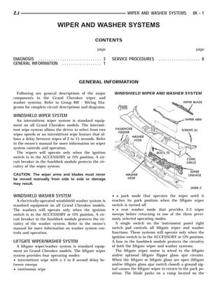
Following are general descriptions of the major WINDSHIELD WIPER AND WASHER SYSTEM
components in the Grand Cherokee wiper and
washer systems. Refer to Group 8W - Wiring Dia-
grams for complete circuit descriptions and diagrams.
WINDSHIELD WIPER SYSTEM
An intermittent wiper system is standard equip-
ment on all Grand Cherokee models. The intermit-
tent wipe system allows the driver to select from two
wiper speeds or an intermittent wipe feature that al-
lows a delay between wipes of 2 to 15 seconds. Refer
to the owner’s manual for more information on wiper
system controls and operation.
The wipers will operate only when the ignition
switch is in the ACCESSORY or ON position. A cir-
cuit breaker in the fuseblock module protects the cir-
cuitry of the wiper system.
CAUTION: The wiper arms and blades must never
be moved manually from side to side or damage
may result.
WINDSHIELD WASHER SYSTEM • a park mode that operates the wiper until it
A electrically-operated windshield washer system is reaches its park position when the liftgate wiper
standard equipment on all Grand Cherokee models. switch is turned off
The washers will operate only when the ignition • a rear washer mode that provides 2-3 wiper
switch is in the ACCESSORY or ON position. A cir- sweeps before returning to one of the three previ-
cuit breaker in the fuseblock module protects the cir- ously selected operating modes.
cuitry of the washer system. Refer to the owner’s A single switch on the instrument panel right
manual for more information on washer system con- switch pod controls all liftgate wiper and washer
trols and operation. functions. These systems will operate only when the
ignition switch is in the ACCESSORY or ON position.
LIFTGATE WIPER/WASHER SYSTEM A fuse in the fuseblock module protects the circuitry
A liftgate wiper/washer system is standard equip- of both the liftgate wiper and washer systems.
ment on Grand Cherokee models. The liftgate wiper The liftgate wiper motor is wired to the liftgate
system provides four operating modes: and/or optional liftgate flipper glass ajar circuits.
• intermittent wipe with a 5 to 8 second delay be- When the liftgate or liftgate glass are open (liftgate
tween sweeps and/or liftgate glass ajar switch closed) a ground sig-
• continuous wipe nal causes the liftgate wiper to return to the park po-
sition. The blade parks on a ramp located on the
2. 8K - 2 WIPER AND WASHER SYSTEMS ZJ
liftgate panel below the liftgate glass. Refer to the bly must be replaced. The crank arm, mounting
owner’s manual for more information on liftgate wip- bracket, and other linkage are serviced only as an as-
er/washer system controls and operation. sembly.
WIPER ARMS, BLADES, AND ELEMENTS LIFTGATE WIPER MOTOR
All Grand Cherokee models have two 20-inch wind- The liftgate wiper motor contains integral elec-
shield wiper blades with replaceable rubber elements tronic controls and a transmission to provide four op-
(squeegees). The liftgate wiper uses a single 12-inch erating modes:
wiper blade with a replaceable rubber element • intermittent wipe with a fixed 5 to 8 second delay
(squeegee). between wipes
Caution should be exercised to protect the rubber • continuous wipe
squeegees from any petroleum-based cleaners or con- • a park mode that operates the wiper until it
taminants, which will rapidly deteriorate the squee- reaches its park position when the liftgate wiper
gee rubber. If squeegees are damaged, worn or switch is turned off
contaminated they must be replaced. • a rear washer mode that provides 2-3 wiper
Wiper squeegees exposed to the weather for a long sweeps before returning to one of the three previ-
time tend to lose their wiping effectiveness. Periodic ously selected operating modes.
cleaning of the squeegees is suggested to remove de- The liftgate wiper motor can not be repaired. If
posits of salt and road film. The wiper blades, arms faulty, the entire assembly must be replaced.
and windshield or liftgate glass should be cleaned
with a sponge or cloth and a mild detergent or non-
WINDSHIELD WIPER/WASHER SWITCH
Controls for the windshield wiper and washer sys-
abrasive cleaner. If the squeegees continue to streak
tems are contained in the multi-function switch con-
or smear, they should be replaced.
trol lever. The multi-function switch is mounted on
The blades are mounted to spring-loaded wiper
the left side of the steering column between the
arms. Spring tension of the wiper arms controls the steering wheel and the instrument panel. This switch
pressure applied to the blades on the glass. The also controls many other functions. The multi-func-
windshield wiper arms are attached by an integral tion switch can not be repaired. If any function of the
latch to the two wiper pivots on the cowl grille panel switch is faulty, the entire switch must be replaced.
at the base of the windshield. The liftgate wiper arm
is attached by a nut under the blade pivot end cover LIFTGATE WIPER/WASHER SWITCH
directly to the liftgate wiper motor output shaft on The single two-function switch on the instrument
the liftgate panel. The wiper arms and blades can panel right of the steering column controls the lift-
not be adjusted or repaired. If faulty, they must be gate wiper and washer functions. The sliding-type
replaced. switch features a detent in the ON and DELAY posi-
tions. The switch knob is pushed in to activate the
WIPER LINKAGE AND PIVOTS WASH function. Both the liftgate wiper and liftgate
The wiper linkage, pivots, and motor are installed washer motors will operate continuously for as long
in the vehicle and removed as a unit. These compo- as the switch is held in the WASH position. The
nents are all mounted to a bracket, which is bolted to switch can not be repaired; if faulty, it must be re-
another bracket in the cowl plenum area beneath the placed.
cowl plenum screen. The linkage, pivots, and bracket
are serviced only as an assembly. The wiper motor is INTERMITTENT WIPE MODULE
available as a separate service item. In addition to low and high speed, the intermittent
wipe system has a delay mode. The delay mode has a
WINDSHIELD WIPER MOTOR range of 2 to 20 seconds. The length of the delay is
The two-speed permanent magnet wiper motor has selected with a variable resistor in the wiper (multi-
an integral transmission and park switch. The motor function) switch and is accomplished by electronic
is mounted to the wiper linkage module with 3 circuitry within the intermittent wipe module. If the
screws and a nut that secures the crank arm to the washer knob is depressed while the wiper (multi-
motor output shaft. function) switch is in the OFF position, the intermit-
Wiper speed is controlled by current flow to the ap- tent wipe module will operate the wiper motor for
propriate set of brushes. The wiper motor completes approximately 2 wipes and automatically turn the
its wipe cycle when the switch is turned OFF. An in- motor off.
ternal park switch maintains current to the motor The intermittent wipe module is mounted to the
brushes until the wiper arms reach the lowest por- left cowl side panel under the instrument panel and
tion of the wipe pattern. The wiper motor assembly behind the cowl side trim with a hook and loop fas-
can not be repaired. If faulty, the entire motor assem- tener patch. The module can not be repaired.
3. ZJ WIPER AND WASHER SYSTEMS 8K - 3
WINDSHIELD WASHER NOZZLES low washer fluid level sensor. Refer to Group 8E - In-
The two fluidic washer nozzles are snapped into strument Panel and Gauges for diagnosis and service
openings in the cowl grille panel below the wind- of the sensor. The reservoir and filler cap are avail-
shield and are not adjustable. Washer fluid is fed to able for service.
the nozzles through hoses clipped to the underside of
the cowl grille panel. The nozzles can not be repaired WASHER PUMPS
and, if faulty, should be replaced. Two washer pump and motor units are mounted
near the bottom of the washer reservoir, one each for
LIFTGATE WASHER NOZZLE the windshield and liftgate washer systems. A
The single liftgate washer nozzle snaps into a hole threaded nipple on the pump is installed through a
in the center of the upper liftgate panel above the grommet in the bottom of the single reservoir. A fil-
liftgate glass. Washer fluid is fed to the nozzle from
ter/nut is installed through the reservoir filler open-
the washer reservoir in the engine compartment. A
ing to the threaded nipple to hold the pump/motor
liftgate washer hose system is routed through the
unit in place. A permanently lubricated and sealed
body of the vehicle with the left body wiring harness
motor is coupled to the rotor-type pump. Washer
from the reservoir to the liftgate. The nozzle can not
be repaired and, if faulty, should be replaced. fluid is gravity fed from the reservoir to the pump.
The pump then pressurizes the fluid and forces it
WASHER RESERVOIR through the plumbing to the nozzles when the motor
The washer solvent reservoir is mounted to the left is energized. The pump and motor can not be re-
front inner fender shield near the cowl panel. The paired. If faulty, the entire assembly must be re-
same reservoir is used for both the windshield and placed.
liftgate washer systems. It also has a provision for a
DIAGNOSIS
WINDSHIELD WIPER SYSTEM (3) With ignition switch OFF and wiring harness
(1) Remove circuit breaker from fuseblock module connector (multi-function switch side) still un-
and turn ignition switch to ACCESSORY or ON. plugged.
(a) Measure voltage at battery side of circuit (a) Measure resistance between unplugged con-
breaker cavity. Meter should read battery voltage. nector terminals A and G while rotating wiper
If not OK, repair wiring from ignition switch. switch from minimum to maximum DELAY. Meter
(b) Measure resistance across circuit breaker ter- should read from zero to 300K ohms. If not OK, re-
minals. Meter should read zero ohms. If not OK, pair wiring from wiper switch and/or see Wind-
replace failed circuit breaker. shield Wiper/Washer Switch diagnosis.
(2) Unplug wiper (multi-function) switch side of (b) Measure resistance between unplugged con-
wiring harness connector from intermittent wipe nector terminals D and G while rotating wiper
module and turn ignition switch to ACCESSORY or switch from minimum to maximum DELAY. Meter
ON. should read from zero to 300K ohms. If not OK, re-
(a) Measure voltage at unplugged connector ter- pair wiring from wiper switch and/or see Wind-
minal D. Meter should read battery voltage. If not shield Wiper/Washer Switch diagnosis.
OK, repair wiring from circuit breaker through (4) Unplug wiring harness connector (wiper motor
multi-function switch connector cavity 4. See Wind- side) from intermittent wipe module. Turn wiper
shield Wiper/Washer Switch diagnosis for more in- switch to LOW or HIGH, then plug both unplugged
formation. harness connectors into each other. Turn ignition
(b) Turn wiper switch to LOW. Measure voltage switch to ACCESSORY or ON.
at unplugged connector terminal E. Meter should
read battery voltage. If not OK, repair wiring from CAUTION: DO NOT move the wiper switch to DE-
wiper switch and/or see Windshield Wiper/Washer LAY with the intermittent wiper module removed
Switch diagnosis. from the circuit. If the switch is moved to the DE-
(c) Turn wiper switch to HIGH. Measure voltage LAY position during the next step, the switch will be
at unplugged connector terminal C. Meter should damaged.
read battery voltage. If not OK, repair wiring from
wiper switch and/or see Windshield Wiper/Washer (a) Test wiper operation in LOW and HIGH
Switch diagnosis. speed modes, and test washer operation. If these
4. 8K - 4 WIPER AND WASHER SYSTEMS ZJ
modes were inoperative, but are OK now, replace (e) Wiper switch in LOW or HIGH, voltmeter
failed intermittent wipe module. If not OK, rein- connected to terminal 2. Turn wiper switch to OFF
stall intermittent wipe module and go to next step. and observe meter. Meter should read battery volt-
age when switch goes to OFF, then zero volts after
CAUTION: When replacing intermittent wipe mod- wipers park. If battery voltage present, but wipers
ule, be certain to use the correct replacement mod- fail to park, replace failed wiper motor. If no bat-
ule. If an incorrect substitution is used, the wiper tery voltage present, repair wiring to intermittent
delay will be incorrect. wipe module.
(5) Turn ignition switch to ACCESSORY or ON, WINDSHIELD WASHER SYSTEM
and turn wiper switch to LOW or HIGH. Measure (1) With ignition switch in OFF position, unplug
voltage at either intermittent wipe module connector front washer pump wiring connector. Measure resis-
terminal F and move wiper switch to OFF. Meter tance from terminal A of front pump connector to a
should show battery voltage until wipers park, and good ground. Meter should read zero ohms. If not
then zero volts. If OK, go to step 6. If not OK, check OK, repair wiring to ground.
wiring to wiper motor and perform Windshield Wip- (2) Remove circuit breaker from fuseblock module
er/Washer Switch diagnosis, then go to step 6. and turn ignition switch to ACCESSORY or ON.
(6) To test the wiper motor, turn the ignition (a) Measure voltage at battery side of circuit
switch to ACCESSORY or ON. Position the wiper breaker cavity. Meter should read battery voltage.
switch and probe the motor connector (Fig. 1) as in- If not OK, repair wiring from ignition switch.
dicated in the following steps. (b) Measure resistance across circuit breaker ter-
minals. Meter should read zero ohms. If OK, rein-
stall circuit breaker. If not OK, replace failed
circuit breaker.
(3) Unplug wiring harness connector (multi-func-
tion switch side) from intermittent wipe module, and
turn ignition switch to ACCESSORY or ON. Measure
voltage at unplugged connector terminal B while
washer switch is depressed. Meter should read bat-
tery voltage. If OK, reinstall connector. If not OK, re-
pair wiring back to circuit breaker and/or see
Windshield Wiper/Washer Switch diagnosis.
(4) Unplug wiring harness connector (washer
pump side) from intermittent wipe module, and turn
ignition switch to ACCESSORY or ON. Measure volt-
age at unplugged connector terminal B while washer
switch is depressed. Meter should read battery volt-
age. If OK, reinstall connector. If not OK, replace
Fig. 1 Wiper Motor Connector failed intermittent wipe module.
(a) Wiper switch in OFF position, measure resis-
CAUTION: When replacing intermittent wiper mod-
tance between terminal 4 and a good ground.
ule, be certain to use the correct replacement mod-
Meter should read zero ohms. If not OK, repair
ule. If an incorrect substitution is used, the wiper
wiring to ground.
delay will be incorrect.
(b) Wiper switch in any position, measure volt-
age at terminal 1. Meter should read battery volt- (5) With ignition switch in ACCESSORY or ON,
age. If not OK, repair wiring to intermittent wipe unplug connector at front washer pump. Measure
module. voltage at washer pump connector terminal A while
(c) Wiper switch in LOW, measure voltage at ter- washer switch is depressed. Meter should read bat-
minal 5. Meter should read battery voltage. If OK, tery voltage. If OK, replace failed front washer pump.
but wipers do not operate, replace failed wiper mo- If not OK, repair wiring from intermittent wipe mod-
tor. If not OK, repair wiring to intermittent wipe ule.
module.
(d) Wiper switch in HIGH, measure voltage at WINDSHIELD WIPER/WASHER SWITCH
terminal 6. Meter should read battery voltage. If Use an ohmmeter to test for continuity (no resis-
OK, but wipers do not operate, replace failed wiper tance) between the terminals of the switch as shown
motor. If not OK, repair wiring to intermittent wipe in the Multi-Function Switch Continuity chart (Fig.
module. 2). If not OK, replace the switch.
5. ZJ WIPER AND WASHER SYSTEMS 8K - 5
WINDSHIELD WIPER/WASHER SYSTEM SCHEMATIC
The intermittent wipe module is attached to the
left cowl side panel beneath the instrument panel
and behind the cowl side trim panel with a hook and
loop fastener patch.
The following tests are to be performed if a prob-
lem with wiper system is only evident in the DELAY
mode. These tests involve disconnecting the intermit-
tent wipe module.
CONDITION
Excessive delay (more than 30 seconds) or in-
adequate variation in delay.
PROCEDURE
Variations in delay should be as follows:
(1) Minimum delay (delay control to extreme coun-
terclockwise position before first detent) 1/2 to 2 sec-
onds.
(2) Maximum delay (delay control to extreme clock-
wise position before off detent) 10 to 30 seconds.
(3) If there is excessive delay or no variations in
delay, see Windshield Wiper/Washer Switch diagno-
Fig. 2 Multi-Function Switch Continuity
sis.
INTERMITTENT WIPE MODULE
The intermittent wipe module is non-serviceable. CONDITION
Refer to Group 8W - Wiring Diagrams for more infor- In DELAY mode wipers run continually when
mation. washers are operated, but do not provide an ex-
tra wipe when the wash switch is released.
6. 8K - 6 WIPER AND WASHER SYSTEMS ZJ
PROCEDURE (2) Remove liftgate cover. See Liftgate Wiper Motor
Replace the intermittent wipe module. service procedures.
(3) Measure resistance between rear wiper motor
CAUTION: When replacing intermittent wipe mod- connector terminal 3 and ground. Meter should read
ule, be certain to use the correct replacement mod- zero ohms. If OK, go to next step. If not OK, repair
ule. If an incorrect substitution is used, the wiper wiring to ground.
delay will be incorrect. (4) With liftgate and liftgate glass closed, check for
continuity between rear wiper motor connector termi-
nal 6 and ground. There should be no continuity. If
CONDITION
OK, go to next step. If not OK, repair liftgate or lift-
Wipers start erratically during DELAY mode.
gate glass ajar switch and wiring as necessary.
PROCEDURE (5) Turn ignition switch to ON and place liftgate
(1) Verify that the ground connection at the instru- wiper switch in WASH. Measure voltage at rear
ment panel is making good connection (free from wiper motor connector terminal 5. Meter should read
paint) and is tight. battery voltage. If OK, go to next step. If not OK, go
(2) Verify that the wiring ground connections are to step 7.
tight and have good contact. (6) Place liftgate wiper switch in ON. Measure
(3) Verify that the wiring ground connections for voltage at liftgate wiper motor connector terminal 2.
the intermittent wipe module and the windshield Meter should read battery voltage. If not OK, go to
wiper/washer switch are tight. step 7.
(4) If condition is not corrected, replace intermit- (7) Remove liftgate wiper switch and reconnect be-
tent wipe module. low instrument panel. Back probe liftgate wiper
switch connector with ignition switch in ON position.
CAUTION: When replacing intermittent wipe mod- (8) Measure voltage at liftgate wiper switch con-
ule, be certain to use the correct replacement mod- nector terminal 1. Meter should read battery voltage.
ule. If an incorrect substitution is used, the wiper If not OK, repair open to fuse 9.
delay will be incorrect. (9) Push liftgate wiper switch to WASH. Measure
voltage at liftgate wiper switch connector terminal 4.
Meter should read battery voltage. If OK, repair open
LIFTGATE WIPER SYSTEM to liftgate wiper motor terminal 5. If not OK, replace
(1) Remove and inspect 20 amp fuse 9 in the fuse- switch.
block module. If OK, re-install fuse and go to next (10) Move liftgate wiper switch to ON. Measure
step. If not OK, replace fuse. voltage at liftgate wiper switch connector terminal 3.
LIFTGATE WIPER/WASHER SYSTEM SCHEMATIC
7. ZJ WIPER AND WASHER SYSTEMS 8K - 7
Meter should read battery voltage. If OK, repair open LIFTGATE WIPER/WASHER SWITCH
to liftgate wiper motor terminal 2. If not OK, replace
switch.
(11) Move liftgate wiper switch to DELAY. Measure
voltage at switch connector terminal 2. Meter should
read battery voltage. If OK, repair open to liftgate
wiper motor terminal 4. If not, replace switch.
LIFTGATE WASHER SYSTEM
(1) Turn ignition switch to ON and place liftgate
wiper switch in ON. If motor does not operate check
fuse 9 in the fuseblock module.
(2) Unplug liftgate washer pump connector.
(3) Measure resistance at pump connector terminal
B (ignition switch OFF). Meter should read zero
ohms. If not OK, repair wiring to ground. (8) Measure voltage at liftgate wiper switch con-
(4) Turn ignition switch to ON. nector terminal 4, switch in WASH. Meter should
(5) Measure voltage at pump connector terminal A, read battery voltage. If not OK, replace switch.
liftgate wiper switch in WASH. Meter should read
battery voltage. If OK, replace pump. If not OK, go to LIFTGATE WIPER/WASHER SWITCH
next step. Use an ohmmeter to test switch resistance as
(6) Remove liftgate wiper switch and reconnect be- shown in the following chart. If switch fails to per-
low instrument panel. Back probe liftgate wiper form as shown, replace faulty switch.
switch connector with ignition switch in ON.
(7) Measure voltage at liftgate wiper switch con-
nector terminal 1. Meter should read battery voltage.
If not, repair wiring to fuse 9.
8. 8K - 8 WIPER AND WASHER SYSTEMS ZJ
SERVICE PROCEDURES
WINDSHIELD WIPER MOTOR REMOVE/INSTALL • linkage assembly screws to 8 N⅐m (72 in. lbs.).
(1) Remove wiper arms by lifting up wiper arm
and slide tab out.
(2) Remove 6 screws holding the cowl grille (Fig.
3).
Fig. 5 Windshield Wiper Arms Install
LIFTGATE WIPER MOTOR REMOVE/INSTALL
(1) Lift cover off wiper arm pivot (Fig. 6).
Fig. 3 Wiper Linkage Remove/Install
(3) Disconnect washer hose and set cowl grille
aside.
(4) Remove 5 bolts holding wiper linkage assembly.
(5) Turn linkage over and remove the nut holding
the crank arm to the motor.
(6) Remove 3 screws holding motor to linkage (Fig.
4) and remove motor.
Fig. 6 Liftgate Wiper Arm Remove
(2) Remove wiper arm retaining nut and wiper
arm.
(3) Remove motor retaining nut (Fig. 7).
(4) Remove external bezel.
(5) Remove screws holding liftgate interior trim
panel.
(6) Remove the trim panel with a wide, flat-bladed
tool (Fig. 8).
(7) Unplug harness connector from rear wiper mo-
tor.
(8) Remove 2 wiper motor mounting bolts.
Fig. 4 Windshield Wiper Motor Remove/Install (9) Remove wiper motor.
(7) Reverse removal procedures to install. Index (10) Reverse removal procedures to install. Posi-
wiper arms as shown in Fig. 5. Tighten hardware as tion wiper blade as shown in Fig. 9. Tighten hard-
follows: ware as follows:
• motor screws to 5-7 N⅐m (44-62 in. lbs.) • motor mounting bolts to 1-1.7 N⅐m (10-15 in. lbs.)
• crank arm to motor nut to 10-12 N⅐m (88-106 in. • motor mounting nut to 4-5.6 N⅐m (35-50 in. lbs.)
lbs.) • wiper arm retaining nut to 18 N⅐m (160 in. lbs.).
9. ZJ WIPER AND WASHER SYSTEMS 8K - 9
Fig. 7 Liftgate Wiper Motor Remove/Install
Fig. 9 Liftgate Wiper Arm Positioning
(7) Lower steering column to gain access to rear of
multi-function switch.
Fig. 8 Liftgate Trim Panel Remove To aid in removal (8) Remove multi-function switch tamper proof
of the trim panel, start at the bottom of the panel. mounting screws (tamper proof torx bit Snap-On
TTXR20B2 or equivalent required).
WINDSHIELD WIPER/WASHER SWITCH (9) Gently pull switch away from column. Loosen
REMOVE/INSTALL connector screw. The screw will remain in the con-
(1) Disconnect battery negative cable. nector.
(2) Remove tilt lever (tilt column only). (10) Remove wiring connector from multi-function
(3) Remove both upper and lower steering column switch (Fig. 11).
covers. Requires removal of 3 screws (Torx T-20). (11) Reverse removal procedures to install. Tighten
(4) Remove 4 screws holding steering column trim hardware as follows:
panel (Fig. 10). • switch connector retaining screw to 2 N⅐m (17 in.
(5) Remove 6 screws holding knee blocker. lbs.)
(6) Remove steering column retaining nuts. • switch retaining screws to 2 N⅐m (17 in. lbs.)
• steering column nuts to 12 N⅐m (105 in. lbs.)
10. 8K - 10 WIPER AND WASHER SYSTEMS ZJ
Fig. 10 Steering Column Trim and Knee Blocker
Fig. 12 Remove Center Bezel Upper Screws
Fig. 11 Multi-Function Switch
• steering column cover screws to 2 N⅐m (17 in. lbs.). Fig. 13 Upper Dash Pad Attaching Screws
ter holding dash pad (Fig. 14).
LIFTGATE WIPER/WASHER SWITCH REMOVE/
INSTALL
(1) Disconnect battery negative cable.
(2) Remove ash receiver.
(3) Remove 6 screws holding center cluster bezel
(Fig. 12).
(4) Remove center bezel.
(5) Remove 2 screws holding dash pad located be-
hind top of center bezel.
(6) Gently pry defroster grille out of dash pad.
(7) Unplug sensors (if equipped) and set defroster
grille aside.
(8) Remove 4 screws in defroster duct opening Fig. 14 Remove Screws Holding Dash Pad
holding dash pad (Fig. 13).
(9) Remove 3 screws above instrument panel clus-
11. ZJ WIPER AND WASHER SYSTEMS 8K - 11
(10) Open glove box and remove 2 screws holding (15) Remove 6 screws holding knee blocker.
dash pad. (16) Remove steering column retaining nuts.
(11) Remove dash pad pulling up to unsnap end (17) Remove 3 screws holding bottom of bezels
clips. (Fig. 17).
(12) With left front door open, remove 1 screw from
the side of the lower trim panel (Fig. 15).
Fig. 17 Remove Screws Holding Bottom Of Bezels
(18) Remove 2 screws holding top of end and
switch pod bezels (Fig. 18). The end bezel can now be
removed.
Fig. 15 Lower Trim Panel
(13) Remove 4 screws holding the steering column
cover (Fig. 16).
(14) Remove 1 screw from bottom of lower trim
panel and pull panel off. There is also a clip holding
the panel to the instrument panel.
Fig. 18 Remove Screws Holding Top of Bezels
(19) Remove 2 screws holding left side of switch
pod bezel (Fig. 19).
(20) Remove 3 screws holding right side of switch
pod bezel (Fig. 20).
(21) Pull switch pod bezel out far enough to re-
move switch connectors. Disconnect connectors from
each switch pod and remove bezel (Fig. 21).
Fig. 16 Steering Column Cover and Knee Blocker (22) Remove required switch attaching screws and
switch.
12. 8K - 12 WIPER AND WASHER SYSTEMS ZJ
Fig. 19 Left Switch Pod Bezel Screws Fig. 20 Right Switch Pod Bezel Screws
(23) Reverse the removal procedures to install a
new switch. Tighten steering column retaining nuts
to 105 in. lbs.
WASHER PUMP/RESERVOIR REMOVE/INSTALL
(1) Remove 3 screws holding washer reservoir to
left inner fender shield (Fig. 22).
(2) Disconnect hose from pump(s).
(3) Drain solvent from reservoir into a clean con-
tainer for re-use.
(4) Using a deep socket, remove filter/nut(s) from
bottom inside reservoir and remove pump(s).
(5) Reverse removal procedures to install.
WASHER NOZZLE REMOVE/INSTALL
To remove the washer nozzle, push up on the noz-
zle (Fig. 23). There is a small tang that will release, Fig. 21 Rear View Of Switch Pod Bezel
which allows the nozzle to be removed.
13. ZJ WIPER AND WASHER SYSTEMS 8K - 13
Fig. 22 Washer Reservoir Mounting
Fig. 23 Liftgate Washer Nozzle and Hose - Typical