2. SIGNIFICANT INCREASE IN ACCURACY/SPEED/TORQUE
Adoption of the hollow structure provides hollow rotary series with improved usability
2 High Precision
Hypoid gear with high resolution (0.0015 to 0.0007 deg/pulse)
encoder allows high accuracy ± 0.005 degree.
Can be used as a high precision table.
3 Multi-turn Operation
The operating range is up to ± 9999 degrees * from home.
It is also possible to rotate indenitely in the same direction.
*Depending upon the model
4 High Rigidity
5 No Return to Home
6 Internal Brake (Optional)
1
1 Small
standard Brake
Repeatability
Operating range
up to ±9999°
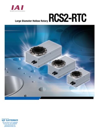
1 Hollow Construction
Large-diameter hollow structure, allows installation of
rotating wires and laying of pipes easier.
To achieve high rigidity, cross-roller bearings are used in the large diameter spindle and table.
Available in small, medium, and large body sizes.
Homing is not required with the absolute encoder type. In the case of an emergency stop, work can resume from the last
stopped position.
Since the brake specication can be selected, the actuator can be powered off but still hold position of the table
during an emergency stop.
Small
high Medium Large Limit Reverse SIGNIFICANT INCREASE SPEED/TORQUE
Adoption of the hollow structure provides a large diameter hollow rotary series with improved usability
±0.005°
Sold Serviced By:
ELECTROMATE
301806_IAI_RCS-RTC_Cat_A4.indd 2 10/11/10 1:48:16 PM
Toll Free Phone (877) SERVO98
Toll Free Fax (877) SERV099
www.electromate.com
sales@electromate.com
3. Rotary product system
2
2
Type
Vertical type
Small
type
Medium
type
Large
type
Type code Output torque
±0.005
5
10
25
0.85 1200
Series Type Encoder type Motor type Operating range Cable length Option
Type
I Incremental
Type Model
Actuator option
I T2
Reduction ratio
RCS2
RTC8L Small standard type
Small
standard type
Cable
Name Cable symbol Standard price
Absolute type RCS2-RTC8L-A-12-24-360-T2 P (1m)
S (3m)
M (5m)
X06(6m)~X10(10m)
X11(11m)~X15(15m)
X16(16m)~X20(20m)
R01(1m)~R03(3m)
R04(4m)~R05(5m)
R06(6m)~R10(10m)
R11(11m)~R15(15m)
R16(16m)~R20(20m)
RCS2-RTC8L-I-12-24-360-T2
RCS2-RTC8HL-A-20-15(24)-360-T2
RCS2-RTC8HL-I-20-15(24)-360-T2
RCS2-RTC10L-A-60-15(24)-360-T2
RCS2-RTC10L-I-60-15(24)-360-T2
RCS2-RTC12L-A-150-18(30)-360-T2
RCS2-RTC12L-I-150-18(30)-360-T2
Brake
Standard price
Option code Standard price
Name
Standard
type
Special
length
Robot
cable
Applicable controller
N None
B Brake
15 Reduction ratio 1/15
T2
SCON
12 12W
A Absolute
360 360 degrees (multiple rotation)
* L (Limit switch) must be specified.
* The value in the brackets shows an alternative reduction ratio that can be selected.
Rotary type
Flat type
Small
type
Medium
type
Large
type
RTBS
RTBSL
Small
type
Medium
type
Large
type
RTC8L
RTC10L
RTC12L
(N・m)
Maximum speed
(degree/s)
Allowable
load moment
(N・m)
0.55
2.8
8.6
750
1200
800
0.36
1.7
4.6
400
600
600
0.36
1.7
4.6
400
600
600
3.6
3.9
17.7
Repeated
Positioning
Accuracy (degree)
±0.05
±0.01
±0.05
±0.01
3.6
3.9
17.7
* Please note that the product cannot be operated when both the output torque and maximum speed
values are simultaneously at the settings given in the above table.
NEW
Small
high output type
Medium type
Large type
Incremental type
Absolute type
Incremental type
Absolute type
Incremental type
Absolute type
Incremental type
B
Limit switch (standard feature)
L
Reverse rotation specication NM
Free of cost
Free of cost
RTC8HL
RTC10L
RTC12L
Small high output type
Medium type
Large type
18
24
30
20
60
150
20W
60W
150W
Reduction ratio 1/18
Reduction ratio 1/24
Reduction ratio 1/30
SSEL
XSEL-P/Q
1m
3m
5m
Specify the length
Robot cable
P
S
M
X□□
R□□
Limit switch (standard feature)
Reverse rotation specification
L
NM
TORQUE
usability
High Standard
output
Servo motor
specification
(RCS2 series)
Pulse motor
specification
(RCP2 series)
Large diameter
hollow type
RTC8HL
RTB
RTBL
RTBB
RTBBL
RTCS
RTCSL
RTC
RTCL
RTCB
RTCBL
Sold Serviced By:
ELECTROMATE
301806_IAI_RCS-RTC_Cat_A4.indd 3 10/11/10 1:48:18 PM
Toll Free Phone (877) SERVO98
Toll Free Fax (877) SERV099
www.electromate.com
sales@electromate.com
4. 33 System 3 System configuration
Applicable Positioner * Controller Cylinder Options
Supported For position (For program PCON, ROBONET, ASEP, (PSEL,XSEL)
configuration
Connection of the SCON controller
Motor cable
Motor cable
CB-RCC-MA□□□
Model: CB-RCC-MA□□□
Motor robot cable
Model: CB-RCC-MA□□□-RB
Encoder cable
Rotary main unit SCON
Teaching box
(optional)
Model: CON-PT-M
Teaching box
(optional)
Model: CON-PT-M
Model: CON-T
Model: RCM-E
Model: RCM-P
Computer
PLC
PLC
I/O flat cable
Model CB-PAC-PIO020
Standard 2 m
(Accessory included with the controller)
Encoder cable
I/O flat cable
Model CB-PAC-PIO020
Standard 2 m
(Accessory included with the controller)
Field network (optional)
(Refer to the ROBO Cylinder
General Catalog for details)
Computer software (optional)
Computer software (optional)
for RS232 connection
Rotary main unit SCON
Model: CB-RCS2-PLA□□□
Encoder robot cable
Model: CB-X2-PLA□□□
Single-Phase AC100V
Main power
Single-Phase AC200V
Connection of SSEL controller
Rotary main unit
Main power
Main power
Motor cable
Model: CB-RCC-MA□□□
Motor robot cable
Model: CB-RCC-MA□□□-RB
Encoder cable
Model: CB-RCS2-PLA□□□
Encoder robot cable
Model: CB-X2-PLA□□□
Main power
Single-Phase AC200V
Connection of XSEL controller
Motor cable
Model: CB-RCC-MA□□□
Motor robot cable
Model: CB-RCC-MA□□□-RB
Encoder cable
Model: CB-RCS2-PLA□□□
Rotary main unit
Main power
Field network (optional)
(Refer to the ROBO Cylinder
General Catalog for details)
SSEL
for RS232 connection
Model: RCM-101-MW
for USB connection
Model: RCM-101-USB
Teaching box
(optional)
Model: SEL-T-J
Model: SEL-TD-J
Teaching box
(optional)
Model: SEL-T-J
Model: SEL-TD-J
Computer
PLC
Single-Phase AC100V
* A noise filter must be used with the power
source. (Please refer to the General Catalog
for recommended model)
PLC
I/O flat cable
Model: CB-DS-PIO020
Standard 2 m
(Accessory included with the controller)
I/O flat cable
Model: CB-DS-PIO020
Standard 2 m
(Accessory included with the controller)
Field network (optional)
(Refer to the ROBO Cylinder
General Catalog for details)
Computer software (optional)
Computer software (optional)
for RS232 connection
Motor cable
Model: CB-RCC-MA□□□
Motor robot cable
Model: CB-RCC-MA□□□-RB
Rotary main unit
Encoder cable
Model: CB-RCS2-PLA□□□
Encoder robot cable
Model: CB-X2-PLA□□□
Single-Phase AC100V
Field network (optional)
(Refer to the ROBO Cylinder
General Catalog for details)
Connection of the SCON controller
Connection of SSEL controller
Connection of XSEL controller
* A noise filter must be used with the power
source. (Please refer to the General Catalog
for recommended model)
I/O flat cable
Model: CB-X-PIO020
Standard 2m
(Accessory included with the controller)
XSEL
for RS232 connection
Model: IA-101-X-MW-J
for USB connection
Model: IA-101-X-USB
Teaching box
(optional)
Model: SEL-T
Teaching box
(optional)
Model: SEL-T
Model: SEL-TD
Computer
PLC
SSEL
Single-Phase AC100V
PLC
I/O flat cable
Model: CB-X-PIO020
Standard 2m
(Accessory included with the controller)
Computer
Field network (optional)
(Refer to the ROBO Cylinder
General Catalog for details)
Computer software (optional)
Computer software (optional)
for RS232 connection
for RS232 connection
Model: IA-101-X-MW
* A noise filter must be used with the power
source. (Please refer to the General Catalog
for recommended model)
for USB connection
Motor cable
Model: CB-RCC-MA□□□
Motor robot cable
Model: CB-RCC-MA□□□-RB
Rotary main unit
Encoder cable
Model: CB-RCS2-PLA□□□
Encoder robot cable
Model: CB-X2-PLA□□□
Encoder robot cable
Model: CB-X2-PLA□□□
Single-Phase AC200V
Field network (optional)
(Refer to the ROBO Cylinder
General Catalog for details)
Name Specification
Model: Motor robot cable
Model: CB-RCC-MA□□□-RB
(Note 1) Model: CB-RCS2-PLA□□□
Encoder robot cable
Model: CB-X2-PLA□□□
Single-Phase AC200V
Model: CON-T
Model: RCM-E
Model: RCM-P
Model: RCM-101-MW
for USB connection
Model: RCM-101-USB
Single-Phase AC200V
Model: IA-101-X-MW-J
for USB connection
Model: IA-101-X-USB
Main power
Single-Phase AC200V
Three-Phase AC200V
Model: SEL-TD
Model: IA-101-X-MW
for USB connection
Model: IA-101-X-USBMW
Model
Speed Operating Motor Output Maximum Positioning Backlash
Allowable Allowable Allowable Home Origin Brake Operational Inside Outer dimensions Weight Positioner Program Program Program Program * A noise filter must be used with the power
source. (Please refer to the General Catalog
for recommended model)
* A noise filter must be used with the power
source. (Please refer to the General Catalog
for recommended model)
XSEL
* A noise filter must be used with the power
source. (Please refer to the General Catalog
for recommended model)
Computer
Computer
Three-Phase AC200V
Model: IA-101-X-USBMW
Sold Serviced By:
ELECTROMATE
301806_IAI_RCS-RTC_Cat_A4.indd 4 10/11/10 1:48:25 PM
301806_Toll Free Phone (877) SERVO98
Toll Free Fax (877) SERV099
www.electromate.com
sales@electromate.com
5. Name of type Small standard type
Small high output type
Degree ±360 (Note 1)
Model
Speed reduction ratio
Operating range
Motor output
Output torque
Maximum operation speed
Positioning repeatability
Backlash
Allowable inertial moment
Allowable thrust load
Allowable load moment
Home detection method
Origin point detection method
Brake retention torque
Operational environment
Inside diameter of hollow shaft
Outer dimensions of the main body (W×L×H)
Weight of the main body
W
N·m
Degree/s
Degree
Degree
kg·m2
N
N·m
N·m
mm
mm
kg
±0.005
±0.05 or lower
RTC10L
60
600
10
0.45
Supported controllers Feature Model Standard price
44
Applicable Controller
Name Model Standard price
Positioner type (Absolute) SCON-C-□A-NP-2-□
SCON-C-□I-NP-2-□
SSEL-C-1-□A-NP-2-□
SSEL-C-1-□I-NP-2-□
XSEL-□-□-□A-N1-EEE-2-□
XSEL-□-□-□I-N1-EEE-2-□ Contact us
* Controller models vary according to the motor output of the rotary and the model/power-supply voltage of the controller. Please refer to the Controller page in the ROBO
Cylinder General Catalog for details.
Options
Teaching box
Easy operation type provided with a touch panel CON-PT-M
For position controller
(PCON, ACON, SCON,
ROBONET, PSEP,
ASEP, ERC2)
For program controller
(PSEL,ASEL,SSEL,
XSEL)
1/15 1/24 1/15 1/24 1/18 1/30
400
Medium type Large type
Specification
(Note 1) Operation range is up to ±9999 degrees.
RTC8L
1/24
12
0.55
750
0.011
85×135×77
2.3
5
0.42
ø30
0.53
1200
0.01
RTC8HL
20
85×150×77
2.4
0.85
750
0.017
Optical encoder (Incremental type/Absolute type)
Proximity sensor method
Temperature 0 - 40℃, humidity 20 to 85%RH or less (no condensation)
ø40
99×171×86
3.5
2.8
750
0.054
RTC12L
150
800
25
1.0
ø54
123×233×92
6.5
5.2
800
0.1
8.6
600
0.17
1.7
1200
0.033
Positioner type (Incremental)
Program control, 1 axis type (Absolute)
Program control, 1 axis type (Incremental)
Program control, multi-axis type (Absolute)
Program control, multi-axis type (Incremental)
Computer software
Teaching box
Computer software
IP54-complient standard type
Affordable basic type
Solely dedicated to data entry with no movement feature
RS232C connection type
USB port connection type
IP54-compliant standard type (for XSEL controller)
IP54-compliant standard type (for PSEL/ASEL/SSEL controller)
3-Position Enable Switch type (for XSEL controller)
3-Position Enable Switch type (for PSEL/ASEL/SSEL controller)
RS232C connection type(for XSEL controller)
RS232C connection type (for PSEL/ASEL/SSEL controller)
USB port connection type(for PSEL/ASEL/SSEL controller)
USB port connection type with an emergency stop switch (for XSEL controller)
CON-T
RCM-E
RCM-P
RCM-101-MW
RCM-101-USB
SEL-T
SEL-T-J
SEL-TD
SEL-TD-J
IA-101-X-MW
IA-101-X-MW-J
IA-101-X-USB
IA-101-X-USBMW
Sold Serviced By:
301806_IAI_RCS-RTC_Cat_A4.indd 5 10/11/10 1:48:29 PM ELECTROMATE
Toll Free Phone (877) SERVO98
Toll Free Fax (877) SERV099
www.electromate.com
sales@electromate.com
6. 5
Outer Dimensions Small type
RCS2-RTC8L (Small standard type)
RCS2-RTC8HL (Small high output type)
4-M5 Depth 10
Medium type
RCS2-RTC10L
5 Carrier Guidelines Please 10.5
(8) 69 (8)
5
100 or higher must be retained
+
Caution
*103.5(RTC8HL)
*88.5(RTC8L)
+0.05
0 16.5
Ø4 Depth 3.5
68
5
4 +0.05
0
Depth 3.5 6-M4 Depth6 2-Ø4 H7
+0.025
0
4-M5 Depth 10
+0.05
0
8-M4 Depth6
99
4-M5 Depth 10
(Maximum screw-in depth 9)
25 25
Ø52
85
4
77
14.5
68
63
6 44
Ø14 3
5
(2)
60°
44.5 (2)
*135(RTC8L)
*150(RTC8HL)
*88.5(RTC8L)
*88.5(RTC8L)
*103.5(RTC8HL)
60°
5.5 30
Depth5
+0.010
0
4 Depth 3.5 +0.05
0
Ø4 +0.05Depth 4
0
4
56
Depth 4 +0.05
0
Ø42 H7
Ø30 (Thru hole)
Ø60 h7
0
−0.030
Ø4 Depth 3.5
*103.5(RTC8HL)
2-Ø4 H7 Depth5 +0.010
0
Ø4 +0.05
0
Depth 4 4 Depth 4 +0.05
0
30
Ø70 h7
0
−0.030
Ø52 H7 +0.030
0
Ø40 (Thru hole)
2-4+0.05 Depth4 (Both front and back)
0
8-M5 Depth10 (Both front and back)
2-Ø4 +0.05
0
Depth4 (Both front and back) 10.5 31
52
171
30
Ø60
(2.5) (2.5) 22.5°22.5°
3
5
Ø14 4
86
72
52
14.5
7
116.5
75
100 or higher must be retained
(7) 85 (7)
60
116.5
5
4-M5 Depth 10
(Dimensions of mounting holes on the side are bilaterally symmetric)
44 6
* The shaded area in
the top view shows
the rotation area.
Caution
* The shaded area in
the top view shows
the rotation area.
The the following ■ ・■ ・・■ ・■ ・■ There Values damage. ・・・Sold Serviced By:
301806_IAI_RCS-RTC_Cat_A4.indd 6 10/11/10 1:48:39 PM ELECTROMATE
Toll Free Phone (877) SERVO98
Toll Free Fax (877) SERV099
www.electromate.com
sales@electromate.com
7. 6
Outer Dimensions
Large type
RCS2-RTC12L
Precautions for Use
6
Carrier Load
Guidelines for Offset Distance
40
22.5°
Model Offset distance (m)
RTC8L 0.10
RTC8HL
RTC10L
RTC12L
22.5°
+0.05
0
Please refer to the Specification Sheet for the values and details of the specifications.
Caution
* The shaded area in
the top view shows
the rotation area.
Brake
Others
100 or higher must be retained
+0.05
0
Output shaft (rotational component) Gap Cylinder (fixed component)
233
64
Ø80
40
Ø14 13.5 31
(2.5) (2.5)
123
(7.5) 108 (7.5)
95
166.5
6
3
92
78
6
9 54
110
166.5
14.5
4
2-Ø5 H7
8-M5 Depth 8
+0.012 Depth6
0
Ø90 h7 0
−0.035
Ø66 H7 +0.030
0
2-5 Depth4 (Both front and back)
2-Ø5 Depth4 (Both front and back) +0.05
0
8-M6 Depth12 (Both front and back)
Ø54 (Thru hole)
Ø5 +0.05Depth 4
0
4-M6 Depth12 5 Depth 4
(Dimensions of mounting holes on the side are bilaterally symmetric)
0.12
0.15
0.20
・ The brake is provided for retention purposes. It should not be used
for braking or emergency stop purposes.
・ Use the brake switch on the controller to manually unlock the
brake.
There is no brake unlock switch on the robot side.
※ Allowable inertia and allowable brake torque do not function
simultaneously. You must check the retention torque.
The more the work part's center of gravity separates from the center of
the rotary shaft, the more it vibrates. Design the tool with reference to the
following table.
■ Acceleration
・ Please set between 0.1 and 0.3G.
■ Speed
・ Maximum speed that the actuator can achieve is shown.
・ It depends on the operational conditions (acceleration, operational
range)
■ Operational range
・ Please note that the operational range can vary with the speed
reduction ratio.
■ Torque
・ The torque specified on the specification is rated torque. Up to three
times the torque may be reached momentarily.
■ Allowable load
There are three items as shown below.
Values over the specified load may shorten the product lifetime or cause
damage. Loads must be set at the allowable value or lower.
・ Allowable inertial moment
・ Allowable thrust load
・ Allowable load moment
・ There is a 1mm gap between the output shaft (rotational component)
and the cylinder (fixed component). (See the diagram below)
・ Please prevent foreign matter from getting into the unit as this may
cause trouble or malfunction.
Sold Serviced By:
301806_IAI_RCS-RTC_Cat_A4.indd 7 10/11/10 1:48:48 PM ELECTROMATE
Toll Free Phone (877) SERVO98
Toll Free Fax (877) SERV099
www.electromate.com
sales@electromate.com
8. CJ0167-1A-UST-1-1010
Guidelines for selecting model: Please refer to the following gures to select the model according to the
shape and mass of the objects mounted on the output shaft.
A Disk-shaped object mounted at the center of the output shaft
For disk shaped objects having their center positioned at the center of the rotary's
output shaft, please refer to the following graphs to find the model that meets both the
mass and radius of the disk.
70
60
50
40
30
20
10
RTC8L 1/24
RTC8HL 1/15
RTC8HL 1/24
RTC10L 1/15
RTC10L 1/24
B Object mounted offset from center of output shaft
For objects offset from the rotary's output shaft, please refer to the following graphs
to select the model that meets both the mass and offset distance of the object.
RTC8L/RTC8HL
Offset distance [cm]
Mass of the object [kg]
18
16
14
12
10
8
6
4
2
0
0 2 4 6 8 10 12 14
RTC10L
Offset distance [cm]
Mass of the object [kg]
30
20
10
0
0 2 4 6 8 10 12 14 16
(Radius of the disk)
r
RTC12L 1/18
RTC12L 1/30
RTC12L
Offset distance [cm]
Mass of the object [kg]
90
80
70
60
50
40
30
20
10
50
40
30
20
10
0
0 5 10 15 20 25
RTC8L 1/24
RTC8HL 1/15
RTC8HL 1/24
RTC10L 1/15
RTC10L 1/24
RTC12L 1/18
RTC12L 1/30
r
(Offset distance)
RTC8L/RTC8HL
Radius of the disk [cm]
Mass of the disk [kg]
45
40
35
30
25
20
15
10
5
0
0
RTC10L
Radius of the disk [cm]
Mass of the disk [kg]
0
0 2 4 6 8 10 12 14 16
RTC12L
Radius of the disk [cm]
Mass of the disk [kg]
0
2 4 6 8 10 12 14 0 5 10 15 20 26
*When using a rotation shaft in the horizontal direction, gravitational loading torque is generated when an object's center of the gravity is
located away from the center of rotation. Either decrease the rotational velocity or reduce the mounted weight.
Sold Serviced By:
ELECTROMATE
Toll Free Phone (877) SERVO98
Toll Free Fax (877) SERV099
www.electromate.com
sales@electromate.com