2. Background Subwoofers are mainly used in home theatre applications, where they are used to portray the special low-
frequency effects of movies and often to augment and extend the bass capabilities of the main front and
surround speakers. A less used, although equally valid application is simply to extend the low-frequency
capability of two-channel audio systems, especially when the main speakers are required to be small.
The demands of movies are wide ranging. Many movies make no pretence at realism, but rather portray
a ‘larger than life’ situation where explosions, earthquakes and the like can make huge demands on the
robustness of a subwoofer. Music reproduction, however, whether through a multi-channel home theatre
installation or a simpler two-channel setup, demands a good deal more finesse and control. There are
many subwoofers available that can thunder away at high levels - sounding impressive to most listeners
who have never experienced a real explosion in their lives - but that give a rather one-note performance
in music. There are others that can perfectly pick out the pitch of every note played on a double bass, but
that cannot cope with the extreme demands of movie effects, at best exhibiting gross distortion and at
worst breaking down. The challenge is to do both things well. At Bowers & Wilkins our roots are in music
reproduction, but we are also associated with some of the world’s most prestigious film studios. Not to
satisfy both requirements would be alien to the way we think.
Speakers required to reproduce very low frequencies at high levels can be large and physically intrusive.
Indeed, if the speaker is passive, the volume is directly determined by the low-frequency extension and
the efficiency. These days, virtually all subwoofers are active and cabinet size can be reduced if electronic
equalisation is used to overcome the natural reduction in bass extension. However, the more the cabinet
size is reduced, the more amplifier power is required to correct the response and the more robust the
drive unit has to be. A suitable compromise has to be struck, depending on how the subwoofer is to be
housed within the listening room. In some cases, the speakers are built into the fabric of the listening
room and hidden away from view. In that case, there is less need to make the speakers very small or
even good looking and any shade of black is acceptable. In other cases, the speakers will be on view, so
styling, size and finish matter.
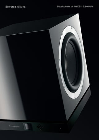
Although we manufacture speakers for custom installation, most subwoofers designed at Bowers &
Wilkins have traditionally been associated with, and taken design cues from our main speaker ranges. So,
for example, subwoofers in the Nautilus and follow-up 800 Series featured curved panel wooden cabinets
and adopted that range’s veneer options. The PV1, in contrast took a more adventurous approach to
design with it’s almost spherical shape and use of an aluminium housing, but both of these features
originated from sound mechanical and electrical principles, fully described in a previous paper.
It was against this background of complex and often disparate requirements that we embarked on the
development of the DB1.
3. Objectives The DB1 development ran parallel to that of the 800 Series Diamond. A commercial decision was made
not to continue with range-dedicated subwoofers, so the DB1 not only had to replace the outgoing
models in being suitable for use with the new Series, but also had to have a wider, cross-range, generic
application.
The following attributes were specified in the product brief:
• Balanced design with two mechanically opposed drive units to minimise cabinet panel
radiation from rocking and resonance.
• 300mm (12in) diameter drive units with long throw capability to achieve required levels
without excessive distortion
• Cabinet to be of wooden construction in order to match the core speaker ranges.
• Cabinet size to be little more than that required to house the drive units.
• Cabinet to be braced to minimise vibration. However, traditional Matrix bracing in its truest
sense was not applicable when most of the internal volume was to be occupied by drive units.
• Amplifier output of 1kW in order to reach required levels.
• Capability of integration with home automation systems of varying complexity.
• Use of digital signal processing to achieve high levels of versatility and adjustment.
• Compensation for poor room acoustics.
• Software controlled menu structure using a small OLED display for parameter adjustment.
• Balanced and unbalanced input options.
• Independent LFE and stereo inputs.
Balanced Design Previous experiments with pressure vessel concepts, which culminated in the PV1 subwoofer, showed
conclusively that coloration from enclosure vibration could be drastically reduced by using two identical
drive units mounted back to back to balance reaction forces.
One of the essential ingredients to producing accurate bass is to give the subwoofer a stable mechanical
foundation. Any rocking motion, which is virtually inevitable with a single drive unit delivering the kind of
low-frequency acoustic output under discussion, reduces the perceived accuracy of the bass and the
harmonic structure that defines how bass notes start and stop. It has long been common practice to
use spike feet to mount speakers on the floor, especially with carpeted floors when the spike can pierce
through the fabric to the hard surface below. This works well to a point, but with suspended wooden
floors, the floor itself can be induced to vibrate. Balancing the subwoofer removes any rocking tendency
and, indeed, effectively isolates the floor without compromising the mechanical grounding.
A secondary benefit to having two drive units symmetrically mounted is that each sees half the internal
volume. You could put a vertical partition midway between the drive units and it would make no difference
to the internal pressure distribution. Airborne resonances within the enclosure therefore start at a
significantly higher frequency and further into the subwoofer’s stop band than if a single drive unit were to
load the same volume.
Cabinet With a pressure vessel design such as the PV1, the curved enclosure walls can be made of thin section
and devoid of internal bracing without compromising the resistance to bending motion. This is because
the forces can be induced to run in the plane of the walls. The constraint on the DB1 that it should be of
rectangular wooden construction meant that the wall thickness must be substantial and internal bracing
added to bring coloration down to acceptable levels.
The enclosure walls are constructed of 25mm (1 in) thick MDF that, together with the substantial 18mm
(¾ in) bracing panels, results in extremely low vibration levels.
4. Drive unit Early prototype subwoofers utilised 250mm (10 in) and 300mm (12 in) drive units from some of our
existing subwoofers, but always with a pair back-to-back. Driving them in parallel was a modified SA1000
amplifier from our Custom Theatre range. Even with 1000 Watts at our disposal and two 12-inch drivers
driven to the full, output was felt to fall short of the sort of sound levels we were trying to achieve. The
first obvious step was to increase amplifier power, but when the SA1000 was replaced by a 1500W per
channel stereo amplifier, each channel driving a single driver (ie 3kW total), the acoustic output did not
appear to increase anywhere near in proportion.
The culprit was found to be the design of suspension used in the drive units. For many years, it has been
considered ‘good practice’ to design rear suspensions (commonly referred to as spiders or dampers)
such that they tighten up at extremes of travel before they hit the magnet top plate. In truth, the sharp
crack heard when a spider hits the top plate with force seldom results in permanent damage, but is
very disconcerting for the average user to hear. This practice has stood us in good stead in passive
vented-box speaker systems, but in this situation, where the driver and enclosure together are operated
over much of their range in the stiffness region, all that extra amplifier power was being wasted trying to
overcome the progressive stiffness of the spider.
A progressive roll spider design was therefore adopted. Here the size of the corrugations varies across
the width of the spider such that the force/displacement graph becomes more linear. Using a 75mm
(3in) diameter voice coil rather than a 100mm (4in) one also proved beneficial in this respect; the greater
distance between the voice coil and the spider gluing platform of the chassis (basket) adding to the spider
linearity. Protection against the spider hitting the top plate is then dealt with by the high stiffness of the air
trapped in the small cabinet and the transfer characteristic of the amplifier.
It was calculated that a linear throw of ±15mm (0.6in) was required to achieve the required sound
pressure levels with low distortionStiffness ofmotor system was designed with a 40mm (1.6in) long voice
and so the Suspension (Kms/x)
coil and 12mm (0.5in) thick top plate. A T-shape centre pole was also used to keep the flux distribution
either side of the top plate as symmetrical as possible. The total throw is ±25mm (1in).
Now the output, even with the 1kW amplifier driving both units in parallel, began to reach the levels we
were looking to achieve, but shortcomings in the robustness of the drive unit quickly became apparent.
The cone – a mix of paper and Kevlar® fibres – was found to delaminate where both the voice coil and roll
surround were attached, and the lead-out tinsels work hardened and fractured.
The first action was to change to a Rohacell® cone, actually a sandwich construction of a Rohacell core
and woven carbon fibre skins, but still the skins delaminated from the core. Here the solution was to add
two plastic reinforcing rings – one to which the voice coil, spider, cone neck and dust cap are attached
and one at the outer rim of the cone where the roll surround is attached.
The tinsel fracture problem was overcome by changing to a multi-core ribbon cable – a technique
common in computer disc drives. This proved resistant to fatigue with the back up that, if one core were
to break, the others would still carry the current.
The final power testing involved 24 subwoofers running at full power continuously for over a month playing
the most demanding movie sequences we could find - and surviving!
5. Electronics The electronics can be divided into five main sections:
Input board
All connectors are mounted on the analogue input board where the audio inputs are buffered from one
another.
Motherboard
This is another analogue board and supports input selection and sensitivity matching to the output level of
the source equipment.
Digital Signal Processing board
All digital processes are carried out on this board, including analogue to digital and digital to analogue
conversion.
DSP is built around an Analog Devices Sigma chip. This is a 28/56bit device, having a high performance
24-bit codec with carefully selected analogue components to complement it. Assembler code is written
directly to the chip for maximum versatility and efficiency. It runs in sample-based processing mode and
has around 50MIPS processing power, 1024 words of program memory and 2048 words of data memory.
With clipping detection built in, the chip contains 21 bi-quads, used as follows:
4 for main equalisation – correcting the natural response of the driver in the cabinet
2 for the Impact overlay – to give a more dramatic EQ for movies
4 for the low-pass filter and phase adjustment
5 for the 5-band graphic equaliser (User EQ)
4 for Room Compensation
2 for Dynamic EQ
An Atmel Arm7-based u-controller drives the GUI, handles home automation and drives the DSP.
Power amplifier and power supply
Mounted within a grounded shielding cage, the module used is an ICEpower ASP1000 combination
1000W switching amplifier and power supply, also used in our SA1000 custom amplifier.
Auxiliary power supply
The auxiliary power supply feeds all low-level circuitry. It is the only power supply active in standby mode
when, in accordance with current legislation, it consumes less than 1 watt.
Auxiliary power supply
Power amplifier and Motherboard
power supply
Input board
Digital Signal
Processing board
6. Firmware The firmware can be divided into two sections – that which controls the graphical user interface (GUI) and
that which controls the digital signal processing (DSP) in the audio path.
User interface Unlike previous subwoofers produced by Bowers & Wilkins, the DB1 has a menu-based interface to
control the setup parameters, compared to the usual proliferation of knobs and switches. The interface
comprises a small OLED display together with a cluster of 5 buttons – up/down/left/right and centre. An
OLED display was chosen in preference to the more common LCD type because of its wider viewing
angle.
It quickly became obvious when designing the menu structure that there are many ways of achieving the
same ends and, for every layout, there will always be someone who doesn’t like it! One only has to look
at the operational differences between the various makes of mobile phone to see that each manufacturer
does it their own way and the conclusion must be that people merely like using what they have become
familiar with. The structure finally adopted attempts to group like operations together in a logical fashion.
In normal operation, the home page of the display simply shows the currently used preset and the Volume
Trim level. Presets are denoted by a number 1 to 5 and may in addition be allocated a name. The Volume
Trim is a volatile gain intended to fine-tune the subwoofer level for individual programme items. If the
subwoofer is switched into standby and on again, this gain is reset to 0dB. Both of these parameters may
be altered by cycling the display page using the left or right buttons and the parameter changed at the
relevant page by using the up and down buttons. Originally, both these parameters were changed directly
from the home page – the volume by the up and down buttons and the presets by left and right – but we
were creating a menu platform that may in future be adapted to a more complex device, so the concept
of ‘hot’ pages that could be cycled through was adopted. Then more pages could be added later if
required.
Pressing and holding the centre button enters and exits the setup routine. The reader is referred to the
product manual where the setup procedure is described in full.
Digital signal processing All filters in the DB1 are implemented in double precision, which maximises resolution throughout the
signal chain without increasing the noise floor.
Advanced acoustic modelling techniques were used in the design of the Dynamic EQ, which alters the
bass alignment on the fly to prevent overload of both drive units and electronics as the output level
increases.
Software The display on the subwoofer is small and located discreetly low down on the subwoofer. For some it
will be difficult to read and operate, so an alternative method of setting the parameters is provided in the
form of a PC application that may be downloaded from our web site. Called SubApp™ (for Subwoofer
Application) it includes two setup features that cannot be undertaken from the GUI on the DB1 itself –
giving a name to presets and executing the room compensation procedure.
The SubApp interface has three pages. The first is entitled Global Settings. There are to be found
parameters that remain the same whatever the application and that are mainly concerned with hardware
compatibility. The second page covers Presets. The 5 presets allow the system to be fine tuned for
different applications. For example, the listener may prefer different settings for listening to music,
watching movies or playing games. Alternatively, different listeners may each prefer different settings for
the same application. The third page deals with the Room Compensation procedure.
Whether setup is undertaken via SubApp or the on-board GUI, changes made become immediately
audible. The provision of 5 presets allows immediate comparison between different options. There is even
the ability to switch the Room Compensation equalisation in and out.
7. Room Compensation At the outset, it is worth pointing out that this is not room correction. The acoustics of the room are not
changed in any way; the effects are merely ameliorated. Furthermore, the compensation applies only
to the subwoofer. No other speakers in the installation are affected. The best solution to correcting bad
acoustics in a listening room remains treatment of the room itself, using traps, absorbers, diffusers and
the like, or some form of active correction. Recognising, however, that many users do not wish to use
such devices for whatever reason, we provide a means of altering the response of the subwoofer such
that excitation of annoying resonances in the room is reduced.
Resonances in rooms can be additive or subtractive. Additive resonances, where the output may
be magnified many times and hang on at discrete frequencies, are the most annoying. Subtractive
resonances involve signal cancellation and result in severe dips in the response. Whilst the ear does
perceive these as wrong, a lack of energy is nowhere near as annoying as an excess.
The equalisation comprises 4 parametric filters. These could be used to reduce output where there are
response peaks and boost output where there are dips. However, boosting output at null frequencies is
virtually a waste of time. If the output is being cancelled by a reflected wave, it matters little at what level
it starts out; the result is more or less the same. For that reason the filters are only used to reduce the 4
most prominent peaks.
It was also decided very early on that two conditions would be applied:
1 The user should have no part in deciding the best equalisation to apply.
2 The compensation should be capable of addressing more than one listening position.
If the user is allowed to make manual adjustments to the correction filters, the way is opened for bad
decisions to be made. No matter how much the nature of resonances is discussed and explained, there
is always the tendency for the user to attempt to fill in response dips, which can lead to overload as more
and more energy is poured into an acoustic black hole. Furthermore, it would be nigh impossible for a
user to analyse a series of measurements from more than one position.
Room resonances change with position of both listener and source and so a universal equalisation of this
type that precisely compensates for every one of a spaced group of listeners is not possible. Indeed, there
is always the danger that a more precise correction at one position will make things worse at another.
The compensation procedure employed here uses 8 measurements taken throughout the whole listening
area. The smaller that area, the more precisely the response can be addressed, but the program analyses
all measurements, extracts common features and only addresses those. So the degree of compensation
is less the larger the listening area.
Here we see two sets of measurements made on the same subwoofer in the same position in the same
room. In both cases, the pre-correction response is in blue and the post correction in red. Both show the
spatial average of the 8 measurements.
In the first, all measurements were taken around a single
listening position. The 4 major peaks have been reduced to
give an overall flatter response.
In the second, the measurements were spread over a 3-seat
sofa and two chairs behind. The peak at 50Hz is common to
all positions and has been depressed, but the one at 75Hz
has been left alone. This is because that peak has high
variance across all the measurement positions and is not a
common artefact.
8. Conclusion The DB1 is an extremely versatile subwoofer that can accommodate a wide range of acoustic
environments, applications and user preferences. It can generate high sound levels with low distortion
and performs well with both movie and music programme, yet is not so large that it becomes excessively
intrusive in the living space.