SlideShare a Scribd company logo
1 of 26
Download to read offline
SERVICE MANUAL
CX5000 series
CX6000 series
84386774A 11/05/2011
EN
Contents
INTRODUCTION
HYDRAULIC, PNEUMATIC, ELECTRICAL, ELECTRONIC SYSTEMS A
PRIMARY HYDRAULIC POWER SYSTEM.............................................. A.10.A
PNEUMATIC SYSTEM ................................................................... A.20.A
ELECTRICAL POWER SYSTEM ........................................................ A.30.A
ELECTRONIC SYSTEM ................................................................. A.50.A
FAULT CODES ........................................................................... A.50.A
ENGINE AND PTO IN ................................................................... B
EXHAUST SYSTEM Emissions control .................................................. B.40.B
TRANSMISSION, DRIVE AND PTO OUT........................................ C
TRANSMISSION Mechanical ............................................................ C.20.B
TRANSMISSION Hydrostatic............................................................. C.20.F
PROCESS DRIVE Primary process drive ................................................ C.50.B
AXLES, BRAKES AND STEERING................................................. D
FRONT AXLE ............................................................................ D.10.A
REAR AXLE .............................................................................. D.12.A
2WD-4WD SYSTEM Hydrostatic......................................................... D.14.E
STEERING Hydraulic..................................................................... D.20.C
STEERING Mechanical .................................................................. D.20.B
SERVICE BRAKE Hydraulic.............................................................. D.30.C
PARKING BRAKE Mechanical ........................................................... D.32.B
FRAME AND CAB ........................................................................ E
USER PLATFORM ....................................................................... E.34.A
ENVIRONMENT CONTROL Heating system ............................................ E.40.B
ENVIRONMENT CONTROL Air-conditioning system .................................... E.40.C
FRAME POSITIONING ................................................................. F
FRAME LEVELLING ..................................................................... F.30.A
TOOL POSITIONING.................................................................... G
84386774A 11/05/2011
LIFTING .................................................................................. G.10.A
LEVELLING .............................................................................. G.30.A
CROP PROCESSING ................................................................... K
FEEDING Reel feeding................................................................... K.25.B
FEEDING Header feeding................................................................ K.25.D
FEEDING Feeder housing ............................................................... K.25.E
THRESHING Conventional threshing .................................................... K.40.B
SEPARATING Beating.................................................................... K.42.B
SEPARATING Rotary separator.......................................................... K.42.C
SEPARATING Straw flow beater ......................................................... K.42.F
SEPARATING Straw walker .............................................................. K.42.E
CLEANING Primary cleaning............................................................. K.62.B
CLEANING Tailings return system ....................................................... K.62.C
STORING AND HANDLING Grain storing ............................................... K.60.B
UNLOADING Grain unloading............................................................ K.72.B
84386774A 11/05/2011
INTRODUCTION
84386774A 11/05/2011
1
INTRODUCTION
Foreword
IMPORTANT INFORMATION
All repair and maintenance works listed in this manual must be carried out only by staff belonging to the NEW HOL-
LAND Service network, strictly complying with the instructions given and using, whenever required, the special tools.
Anyone who carries out the above operations without complying with the prescriptions shall be responsible for the
subsequent damages.
The manufacturer and all the organizations of its distribution chain, including - without limitation - national, regional or
local dealers, reject any responsibility for damages due to the anomalous behavior of parts and/or components not
approved by the manufacturer himself, including those used for the servicing or repair of the product manufactured
or marketed by the Manufacturer. In any case, no warranty is given or attributed on the product manufactured or
marketed by the Manufacturer in case of damages due to an anomalous behavior of parts and/or components not
approved by the Manufacturer.
No reproduction, though partial of text and illustrations allowed
84386774A 11/05/2011
3
INTRODUCTION
Foreword
Technical Information
This manual has been produced by a new technical information system. This new system is designed to deliver
technical information electronically through CD-ROM and in paper manuals. A coding system called ICE has been
developed to link the technical information to other Product Support functions e.g. Warranty.
Technical information is written to support the maintenance and service of the functions or systems on a customers
machine. When a customer has a concern on his machine it is usually because a function or system on his machine
is not working at all, is not working efficiently, or is not responding correctly to his commands. When you refer to the
technical information in this manual to resolve that customers concern, you will find all the information classified using
the new ICE coding, according to the functions or systems on that machine. Once you have located the technical
information for that function or system then you will find all the mechanical, electrical or hydraulic devices, compo-
nents, assemblies and sub assemblies for that function or system. You will also find all the types of information that
have been written for that function or system, the technical data (specifications), the functional data (how it works),
the diagnostic data (fault codes and troubleshooting) and the service data (remove, install adjust, etc.).
By integrating this new ICE coding into technical information , you will be able to search and retrieve just the right
piece of technical information you need to resolve that customers concern on his machine. This is made possible by
attaching 3 categories to each piece of technical information during the authoring process.
The first category is the Location, the second category is the Information Type and the third category is the Product:
• LOCATION - is the component or function on the machine, that the piece of technical information is going to
describe e.g. Fuel tank.
• INFORMATION TYPE - is the piece of technical information that has been written for a particular component or
function on the machine e.g. Capacity would be a type of Technical Data that would describe the amount of fuel
held by the Fuel tank.
• PRODUCT - is the model that the piece of technical information is written for.
Every piece of technical information will have those 3 categories attached to it. You will be able to use any combination
of those categories to find the right piece of technical information you need to resolve that customers concern on his
machine.
That information could be:
• the description of how to remove the cylinder head
• a table of specifications for a hydraulic pump
• a fault code
• a troubleshooting table
• a special tool
84386774A 11/05/2011
4
INTRODUCTION
How to Use this Manual
This manual is divided into Sections. Each Section is then divided into Chapters. Contents pages are included at the
beginning of the manual, then inside every Section and inside every Chapter. An alphabetical Index is included at the
end of a Chapter. Page number references are included for every piece of technical information listed in the Chapter
Contents or Chapter Index.
Each Chapter is divided into four Information types:
• Technical Data (specifications) for all the mechanical, electrical or hydraulic devices, components and, assem-
blies.
• Functional Data (how it works) for all the mechanical, electrical or hydraulic devices, components and assem-
blies.
• Diagnostic Data (fault codes, electrical and hydraulic troubleshooting) for all the mechanical, electrical or hy-
draulic devices, components and assemblies.
• Service data (remove disassembly, assemble, install) for all the mechanical, electrical or hydraulic devices,
components and assemblies.
Sections
Sections are grouped according to the main functions or a systems on the machine. Each Section is identified by
a letter A, B, C etc. The amount of Sections included in the manual will depend on the type and function of the
machine that the manual is written for. Each Section has a Contents page listed in alphabetic/numeric order. This
table illustrates which Sections could be included in a manual for a particular product.
SECTION
A - Distribution Systems
B - Power Production
C - Power Train
D - Travelling
E - Body and Structure
F - Frame Positioning
G - Tool Positioning
H - Working Arm
J - Tools and Couplers
K - Crop Processing
L - Field Processing
PRODUCT
Tractors X X X X X X X X
Vehicles with working arms: backhoes,
excavators, skid steers, .....
X X X X X X X X X
Combines, forage harvesters, balers, .... X X X X X X X X X X
Seeding, planting, floating, spraying
equipment, ....
X X X X X X X X X
Mounted equipment and tools, ..... X X X X
84386774A 11/05/2011
5
INTRODUCTION
This manual contains these Sections. The contents of each Section are explained over the following pages.
Contents
INTRODUCTION
DISTRIBUTION SYSTEMS A
POWER PRODUCTION B
POWER TRAIN C
TRAVELLING D
BODY AND STRUCTURE E
TOOL POSITIONING G
CROP PROCESSING K
Section Contents
SECTION A, DISTRIBUTION SYSTEMS
This Section covers the main systems that interact with most of the functions of the product. It includes the central
parts of the hydraulic, electrical, electronic, pneumatic, lighting and grease lubrication systems. The components that
are dedicated to a specific function are listed in the Chapter where all the technical information for that function is
included.
SECTION B, POWER PRODUCTION
This Section covers all the functions related to the production of power to move the machine and to drive various
devices.
SECTION C, POWER TRAIN
This Section covers all the functions related to the transmission of power from the engine to the axles and to internal
or external devices and additional Process Drive functions.
SECTION D, TRAVELLING
This Section covers all the functions related to moving the machine, including tracks, wheels, steering and braking. It
covers all the axles both driven axles and non-driven axles, including any axle suspension.
SECTION E, BODY AND STRUCTURE
This Section covers all the main functions and systems related to the structure and body of the machine. Including
the frame, the shields, the operator's cab and the platform.
SECTION G, TOOL POSITIONING
This Section covers all the functions related to the final and/or automatic positioning of the tool once the tool is posi-
tioned using the Working Arm or the machine frame.
SECTION K, CROP PROCESSING
This Section covers all the functions related to crop processing.
84386774A 11/05/2011
6
SERVICE MANUAL
HYDRAULIC, PNEUMATIC, ELECTRICAL, ELECTRONIC SYSTEMS
CX5000 series
CX6000 series
84386774A 11/05/2011
A
HYDRAULIC, PNEUMATIC, ELECTRICAL, ELECTRONIC SYSTEMS - PRIMARY HYDRAULIC POWER SYSTEM
PRIMARY HYDRAULIC POWER SYSTEM - Torque
Union nuts
55009 1
Ferrules
The ferrule must be pre-assembled on the tube. Tighten the union nut as specified in the table below. The ferrule and
screw thread are greased.
Torque Nm (lb.ft)Tube outer diameter mm (inch)
Minimum Maximum
8 (0.32) 15 (11) 20 (15)
10 (0.4) 25 (18) 30 (22)
12 (0.47) 35 (26) 40 (29)
16 (0.63) 50 (37) 55 (40)
18 (0.71) 60 (44) 70 (51)
22 (0.87) 100 (74) 110 (81)
28 (1.10) 110 (81) 120 (88)
Metric fittings
Unions
Are suitable for use with union nuts and ferrules and ball-type nipples.
55011 2
84386774A 11/05/2011
A.10.A / 3
HYDRAULIC, PNEUMATIC, ELECTRICAL, ELECTRONIC SYSTEMS - PRIMARY HYDRAULIC POWER SYSTEM
Connections
Are screwed in ISO metric thread - tolerance class 6H - with a tightening torque as specified in the table below.
55012 3
Torque Nm (lb.ft)Tube outer diameter mm (inch)
Minimum Maximum
8 (0,32) 40 (29) 45 (33)
10 (0,40) 65 (48) 70 (51)
12 (0,47) 80 (59) 85 (63)
16 (0,63) 100 (74) 120 (88)
18 (0,71) 120 (88) 140 (103)
22 (0,87) 200 (147) 220 (164)
28 (1,10) 350 (257) 380 (280)
Swivel nut with ball-type nipple
Are suitable for use with female unions
55013 4
D1 Torque Nm (lb.ft)
6H Minimum Maximum
M14 x 1.5 - -
M16 x 1.5 15 (11) 20 (15)
M18 x 1.5 20 (15) 25 (18)
M24 x 1.5 30 (22) 35 (26)
M26 x 1.5 - -
M30 x 2 - -
M36 x 2 - -
84386774A 11/05/2011
A.10.A / 4
HYDRAULIC, PNEUMATIC, ELECTRICAL, ELECTRONIC SYSTEMS - PRIMARY HYDRAULIC POWER SYSTEM
Hydraulic pump - General specification
The hydraulic system contains three hydraulic pumps
ZDF0052A 1
Main hydraulic pump (2)
Type: Silence gear type
Direction of rotation left-hand rotation
Maximum pressure 280 bar ( 4061 psi)
Maximum speed 3000 rpm
Output per revolution 16.5 cc/rev.
Maximum oil flow 48 l/min ( 12.7 gal/min)
Hydraulic pump (Steering circuit) (3)
Type: Silence gear type
Direction of rotation left-hand rotation
Maximum pressure 280 bar ( 4061 psi)
Maximum speed 3000 rpm
Output per revolution 5.5 cc/rev.
Maximum oil flow 12 l/min ( 3.2 gal/min)
Hydraulic pump (Lateral flotation circuit) (4) (if installed)
Type: Gear type
Direction of rotation left-hand rotation
Maximum pressure 230 bar ( 3336 psi)
Maximum speed 3000 rpm
Output per revolution 2 cc/rev.
Maximum oil flow 6 l/min ( 1.6 gal/min)
84386774A 11/05/2011
A.10.A / 5
HYDRAULIC, PNEUMATIC, ELECTRICAL, ELECTRONIC SYSTEMS - PRIMARY HYDRAULIC POWER SYSTEM
PRIMARY HYDRAULIC POWER SYSTEM - Hydraulic schema
1. Engine 20. Reel horizontal adjustment cylinders
2. Pump (main hydraulics) 21. Header and straw elevator reversing valve
3. Pump (steering circuit) 22. Screw couplers with non return valve
4. Pump (lateral flotation) (If installed) 23. Header and straw elevator reversing motor
5. Oil reservoir 24. Steering valve
6. Filler cap with filter 25. Steering cylinder(s)
7. Load sensing valve 27. Load sensing valve
8. Header height control valve 28. Lateral flotation control valve
9. Header cylinders 29. Lateral flotation cylinder
10. Accumulator control valve 30. Lateral float minimum pressure valve ( 60 bar)
11. Header suspension accumulator 30
a.
Lateral float accumulator ( 120 bar)
12. Pressure sensor 30
b.
Lateral float accumulator ( 85 bar)
13. Unloading tube control valve 31. Drain hose
14. Unloading tube cylinder 32. Low pressure filter
15. Reel vertical adjustment valve 33. Breather with filter and non-return valve
16. Reel vertical adjustment cylinders P. Inlet (high pressure)
17. Reel horizontal adjustment valve R. Return (low pressure)
18. Quick-attach coupler - - - Pilot line, load sensing line
19. Non-return valve (single direction restrictor) 42. Pilot valve
P1. P1 = 140 bar for adjustable steering axle (A.S.A.).
P1 = 160 bar for fixed or powered rear axle.
P2. P2 = 200 bar for adjustable steering axle (A.S.A.).
P1 = 220 bar for fixed or powered rear axle.
84386774A 11/05/2011
A.10.A / 6
HYDRAULIC, PNEUMATIC, ELECTRICAL, ELECTRONIC SYSTEMS - PRIMARY HYDRAULIC POWER SYSTEM
PRIMARY HYDRAULIC POWER SYSTEM - Overview
ZEIL11CX0660F0B 1
ZEIL11CX0661F0B 2
84386774A 11/05/2011
A.10.A / 12
HYDRAULIC, PNEUMATIC, ELECTRICAL, ELECTRONIC SYSTEMS - PRIMARY HYDRAULIC POWER SYSTEM
PRIMARY HYDRAULIC POWER SYSTEM - Component localisation
NOTE: To find the location of those components, refer to PRIMARY HYDRAULIC POWER SYSTEM - Overview
(A.10.A)
FRONT
Header
Header quick-release coupler (18)
ZDA6003C 1
Lateral float cylinder (29) (if lateral float installed)
RNIL08CS0002A0B 2
Straw elevator
Header lift cylinders (9)
ZDA5998C 3
84386774A 11/05/2011
A.10.A / 13
HYDRAULIC, PNEUMATIC, ELECTRICAL, ELECTRONIC SYSTEMS - PRIMARY HYDRAULIC POWER SYSTEM
Lateral float accumulator ( 120 bar) (30a)
Lateral float accumulator ( 85 bar) (30b)
ZEIL06CS0141A0B 4
Screw couplers with non return valve (22)
Header and straw elevator reversing motor (23)
ZDA6258B 5
Under cab
Steering valve (24)
ZDA7538A 6
84386774A 11/05/2011
A.10.A / 14
HYDRAULIC, PNEUMATIC, ELECTRICAL, ELECTRONIC SYSTEMS - PRIMARY HYDRAULIC POWER SYSTEM
LEFT-HAND SIDE
Cab left
Load sensing valve (7)
Header height control valve (8)
Unloading tube control valve (13)
Reel vertical adjustment valve (15)
Reel horizontal adjustment valve (17)
Header and straw elevator reversing valve (21)
Load sensing valve (27)
Lateral flotation control valve (28)
Lateral float minimum pressure valve ( 60 bar) (30)
RNPH08CS0008A0B 7
Above front wheel
Unload tube cylinder (14)
ZEIL11CX0662A0B 8
Straw elevator and header engaging cylinder (37)
ZEIL11CX0663A0B 9
Unloading engaging cylinder (41)
ZEIL11CX0664A0B 10
84386774A 11/05/2011
A.10.A / 15
HYDRAULIC, PNEUMATIC, ELECTRICAL, ELECTRONIC SYSTEMS - PRIMARY HYDRAULIC POWER SYSTEM
Middle
Drain hose (31)
ZEIL10CX0188A0Z 11
Above
Threshing engaging clutch (34)
Rotary union (35)
ZEIL06CS0092A0C 12
84386774A 11/05/2011
A.10.A / 16
HYDRAULIC, PNEUMATIC, ELECTRICAL, ELECTRONIC SYSTEMS - PRIMARY HYDRAULIC POWER SYSTEM
ABOVE
Oil reservoir (5)
Filler cap with filter (6)
Breather with filter and non-return valve (33)
Low pressure filter (32)
ZEIL10CX0191A0Z 13
Main hydraulic pump (2)
Pump (3) (Steering circuit)
Pump (4) (Lateral flotation)
ZEIL06CS0150A0B 14
UNDER
Above front axle
Header suspension accumulator (11)
Pressure sensor (12)
RNIL08CS0005A0B 15
At the back
Steering cylinder(s) (25)
ZDA7540A 16
84386774A 11/05/2011
A.10.A / 17
HYDRAULIC, PNEUMATIC, ELECTRICAL, ELECTRONIC SYSTEMS - PRIMARY HYDRAULIC POWER SYSTEM
Stack valve - Dynamic description
If all valves are in the "0" position, then:
The valves (13), (15), (17), (21) and (28), (Refer to Stack valve - Static description (A.10.A)) are closed, which
means that the oil can not flow through these valves.
The pressure raises at (7b), (27b), until the load sensing spool is pushed open against spring pressure (delta P= 3
bar) and the return pressure in the pilot line (7a), (27a). Now pump oil flows into the return line at standby pressure.
When activating the lateral float control spools (if installed), the hydraulic cylinder pressure (pump pressure measured
after the spool restriction) is present in the pilot line (7a), (27a) and closes the load sensing spool. The oil pressure is
available for the activated control spool(s).
When the pump pressure reaches the cylinder pressure (+ 3 bar), the load sensing spool is pushed open. The nec-
essary amount of oil will flow to the control spool at the needed pressure. Excess oil is dumped into the return line.
When activating valves without direct load sensing, (13), (15), (17) and (21), the pilot valve (42) is activated as well to
connect the pressure line with the load sensing line and closes the load sensing spool. The oil pressure is available
for the activated control spool(s).
When the pump pressure reaches the cylinder pressure (+ 3 bar), the load sensing spool is pushed open. The nec-
essary amount of oil will flow to the control spool at the needed pressure. Excess oil is dumped into the return line.
When the cylinder reaches end of stroke, the system pressure starts to raise. When the pilot pressure reaches 207
bar for the main stack valve ( 175 bar for the lateral float stack valve) the pressure relief valve is pushed open and
system pressure is limited to 210 bar (207 + 3 bar)
The load sensing lockout valve ensures that pilot pressure cannot escape into the return.
RNPH08CS0008A0B 1
84386774A 11/05/2011
A.10.A / 18
HYDRAULIC, PNEUMATIC, ELECTRICAL, ELECTRONIC SYSTEMS - PRIMARY HYDRAULIC POWER SYSTEM
Operation of reversing system valve (21).
In neutral position of the valve, both motor connections are connected to each other by the return system. When
switching the valve to position “1" or “2", the pilot valve (42) is activated as well to connect the pressure line with the
load sensing line and closes the load sensing spool. Full oil flow is available towards the hydraulic motor.
RNPH08CS0008A0B 2
Operation of the reel vertical adjustment valve (15).
When switching this valve, the pilot valve (42) is activated as well to connect the pressure line with the load sensing
line and closes the load sensing spool. Full oil flow is available towards the hydraulic cylinder.
These valves are connected to a single-acting cylinder which means that only one lockout valve is provided in the
connection towards the cylinder.
RNPH08CS0008A0B 3
Operation of the unloading tube control valve (13) and the reel horizontal adjustment valve (17).
When switching one of these valves, the pilot valve (42) is activated as well to connect the pressure line with the load
sensing line and closes the load sensing spool. Full oil flow is available towards the hydraulic cylinder.
Lockout valves are installed in the connections towards the cylinder.
RNPH08CS0008A0B 4
84386774A 11/05/2011
A.10.A / 19
Thank you very much for
your reading. Please Click
Here. Then Get COMPLETE
MANUAL. NO WAITING
NOTE:
If there is no response to
click on the link above,
please download the PDF
document first and then
click on it.
HYDRAULIC, PNEUMATIC, ELECTRICAL, ELECTRONIC SYSTEMS - PRIMARY HYDRAULIC POWER SYSTEM
Stack valve - Static description
The main hydraulic system will be a open centre load sensing system that controls all high pressure functions: All
header functions and unloading auger swing.
The hydraulic system contains one stack valve:
• Main stack valve . (see also hydraulic schematic PRIMARY HYDRAULIC POWER SYSTEM - Hydraulic
schema (A.10.A)) Located at the left-hand side of the cab behind the steering platform.
RNPH08CS0008A0B 1
The stack valve consists of two main parts.
• Control valves for oil supply and load sensing (7 and 27)
Refer to PRIMARY HYDRAULIC POWER SYSTEM - Hydraulic schema (A.10.A)
Load sensing is a system which avoids high pressure when the valves are in neutral position and consequently,
less heating up of the oil and creating load-independent flow rate control.
• Control valves with load sensing (13-15-17-21-28)
Refer to PRIMARY HYDRAULIC POWER SYSTEM - Hydraulic schema (A.10.A).
RNPH08CS0008A0B 2
13 Unloading tube movement
15 Reel vertical adjustment
17 Reel horizontal adjustment
21 Reversing system
28 Lateral float system
84386774A 11/05/2011
A.10.A / 20
HYDRAULIC, PNEUMATIC, ELECTRICAL, ELECTRONIC SYSTEMS - PRIMARY HYDRAULIC POWER SYSTEM
Hydraulic pump - Exploded view
ZDF0842A 1
Main hydraulic pump
1 Pump housing 2 Bearing end plate
3 Radial-lip-type oil seal 4 Retaining ring
5 Housing cover 6 Toothed washer
7 Toothed gear 8 Toothed gear
9 Woodruff key 10 Hexagon nut
11 Spring lock washer 12 Protective cap
13 Protective cap 14 Bushing
15 Bushing 16 Head screw
17 Straight pin 18 Straight pin
19 Set of seals
NOTE: Tighten the screw (16) with a torque between 12 - 16 Nm. ( 9 - 12 lb ft)
84386774A 11/05/2011
A.10.A / 21
HYDRAULIC, PNEUMATIC, ELECTRICAL, ELECTRONIC SYSTEMS - PRIMARY HYDRAULIC POWER SYSTEM
Filter - Static description
The low pressure filter (32) is installed on top of the hydraulic reservoir (5) and has a bypass (non-return) valve set to
1.15 bar ( 17 psi).
The return oil from the hydraulics system is flowing through the low pressure filter before entering the hydraulic oil
reservoir.
ZEIL10CX0191A0Z 1
84386774A 11/05/2011
A.10.A / 22
HYDRAULIC, PNEUMATIC, ELECTRICAL, ELECTRONIC SYSTEMS - PRIMARY HYDRAULIC POWER SYSTEM
Breather - Static description
The breather (33) allows the air in the reservoir to escape whenever a considerable oil flow arrives at the reservoir
(e.g. when lowering the attachment).
ZEIL10CX0191A0Z 1
84386774A 11/05/2011
A.10.A / 23

More Related Content

More from uuudfjjdjkskem

Caterpillar cat 277 b multi terrain loader (prefix mdh) service repair manual...
Caterpillar cat 277 b multi terrain loader (prefix mdh) service repair manual...Caterpillar cat 277 b multi terrain loader (prefix mdh) service repair manual...
Caterpillar cat 277 b multi terrain loader (prefix mdh) service repair manual...uuudfjjdjkskem
 
Caterpillar cat 277 multi terrain loader (prefix cnc) service repair manual (...
Caterpillar cat 277 multi terrain loader (prefix cnc) service repair manual (...Caterpillar cat 277 multi terrain loader (prefix cnc) service repair manual (...
Caterpillar cat 277 multi terrain loader (prefix cnc) service repair manual (...uuudfjjdjkskem
 
Caterpillar cat 272 d2 xhp skid steer loader (prefix md2) service repair manu...
Caterpillar cat 272 d2 xhp skid steer loader (prefix md2) service repair manu...Caterpillar cat 272 d2 xhp skid steer loader (prefix md2) service repair manu...
Caterpillar cat 272 d2 xhp skid steer loader (prefix md2) service repair manu...uuudfjjdjkskem
 
Caterpillar cat 272 d2 skid steer loader (prefix bl2) service repair manual (...
Caterpillar cat 272 d2 skid steer loader (prefix bl2) service repair manual (...Caterpillar cat 272 d2 skid steer loader (prefix bl2) service repair manual (...
Caterpillar cat 272 d2 skid steer loader (prefix bl2) service repair manual (...uuudfjjdjkskem
 
Caterpillar cat 259 d compact track loader (prefix gtk) service repair manual...
Caterpillar cat 259 d compact track loader (prefix gtk) service repair manual...Caterpillar cat 259 d compact track loader (prefix gtk) service repair manual...
Caterpillar cat 259 d compact track loader (prefix gtk) service repair manual...uuudfjjdjkskem
 
Caterpillar cat 259 d compact track loader (prefix ftl) service repair manual...
Caterpillar cat 259 d compact track loader (prefix ftl) service repair manual...Caterpillar cat 259 d compact track loader (prefix ftl) service repair manual...
Caterpillar cat 259 d compact track loader (prefix ftl) service repair manual...uuudfjjdjkskem
 
Caterpillar cat 225 excavator (prefix 76 u) service repair manual (76u03765 a...
Caterpillar cat 225 excavator (prefix 76 u) service repair manual (76u03765 a...Caterpillar cat 225 excavator (prefix 76 u) service repair manual (76u03765 a...
Caterpillar cat 225 excavator (prefix 76 u) service repair manual (76u03765 a...uuudfjjdjkskem
 
Caterpillar cat 225 excavator (prefix 76 u) service repair manual (76u02729 0...
Caterpillar cat 225 excavator (prefix 76 u) service repair manual (76u02729 0...Caterpillar cat 225 excavator (prefix 76 u) service repair manual (76u02729 0...
Caterpillar cat 225 excavator (prefix 76 u) service repair manual (76u02729 0...uuudfjjdjkskem
 
Caterpillar cat 225 excavator (prefix 76 u) service repair manual (76u01200 0...
Caterpillar cat 225 excavator (prefix 76 u) service repair manual (76u01200 0...Caterpillar cat 225 excavator (prefix 76 u) service repair manual (76u01200 0...
Caterpillar cat 225 excavator (prefix 76 u) service repair manual (76u01200 0...uuudfjjdjkskem
 

More from uuudfjjdjkskem (9)

Caterpillar cat 277 b multi terrain loader (prefix mdh) service repair manual...
Caterpillar cat 277 b multi terrain loader (prefix mdh) service repair manual...Caterpillar cat 277 b multi terrain loader (prefix mdh) service repair manual...
Caterpillar cat 277 b multi terrain loader (prefix mdh) service repair manual...
 
Caterpillar cat 277 multi terrain loader (prefix cnc) service repair manual (...
Caterpillar cat 277 multi terrain loader (prefix cnc) service repair manual (...Caterpillar cat 277 multi terrain loader (prefix cnc) service repair manual (...
Caterpillar cat 277 multi terrain loader (prefix cnc) service repair manual (...
 
Caterpillar cat 272 d2 xhp skid steer loader (prefix md2) service repair manu...
Caterpillar cat 272 d2 xhp skid steer loader (prefix md2) service repair manu...Caterpillar cat 272 d2 xhp skid steer loader (prefix md2) service repair manu...
Caterpillar cat 272 d2 xhp skid steer loader (prefix md2) service repair manu...
 
Caterpillar cat 272 d2 skid steer loader (prefix bl2) service repair manual (...
Caterpillar cat 272 d2 skid steer loader (prefix bl2) service repair manual (...Caterpillar cat 272 d2 skid steer loader (prefix bl2) service repair manual (...
Caterpillar cat 272 d2 skid steer loader (prefix bl2) service repair manual (...
 
Caterpillar cat 259 d compact track loader (prefix gtk) service repair manual...
Caterpillar cat 259 d compact track loader (prefix gtk) service repair manual...Caterpillar cat 259 d compact track loader (prefix gtk) service repair manual...
Caterpillar cat 259 d compact track loader (prefix gtk) service repair manual...
 
Caterpillar cat 259 d compact track loader (prefix ftl) service repair manual...
Caterpillar cat 259 d compact track loader (prefix ftl) service repair manual...Caterpillar cat 259 d compact track loader (prefix ftl) service repair manual...
Caterpillar cat 259 d compact track loader (prefix ftl) service repair manual...
 
Caterpillar cat 225 excavator (prefix 76 u) service repair manual (76u03765 a...
Caterpillar cat 225 excavator (prefix 76 u) service repair manual (76u03765 a...Caterpillar cat 225 excavator (prefix 76 u) service repair manual (76u03765 a...
Caterpillar cat 225 excavator (prefix 76 u) service repair manual (76u03765 a...
 
Caterpillar cat 225 excavator (prefix 76 u) service repair manual (76u02729 0...
Caterpillar cat 225 excavator (prefix 76 u) service repair manual (76u02729 0...Caterpillar cat 225 excavator (prefix 76 u) service repair manual (76u02729 0...
Caterpillar cat 225 excavator (prefix 76 u) service repair manual (76u02729 0...
 
Caterpillar cat 225 excavator (prefix 76 u) service repair manual (76u01200 0...
Caterpillar cat 225 excavator (prefix 76 u) service repair manual (76u01200 0...Caterpillar cat 225 excavator (prefix 76 u) service repair manual (76u01200 0...
Caterpillar cat 225 excavator (prefix 76 u) service repair manual (76u01200 0...
 

Recently uploaded

John Deere 200lc Excavator Operation And Tests Repair Manual.pdf
John Deere 200lc Excavator Operation And Tests Repair Manual.pdfJohn Deere 200lc Excavator Operation And Tests Repair Manual.pdf
John Deere 200lc Excavator Operation And Tests Repair Manual.pdfExcavator
 
如何办理(UQ毕业证书)昆士兰大学毕业证毕业证成绩单原版一比一
如何办理(UQ毕业证书)昆士兰大学毕业证毕业证成绩单原版一比一如何办理(UQ毕业证书)昆士兰大学毕业证毕业证成绩单原版一比一
如何办理(UQ毕业证书)昆士兰大学毕业证毕业证成绩单原版一比一hnfusn
 
Delhi Call Girls Saket 9711199171 ☎✔👌✔ Full night Service for more than 1 person
Delhi Call Girls Saket 9711199171 ☎✔👌✔ Full night Service for more than 1 personDelhi Call Girls Saket 9711199171 ☎✔👌✔ Full night Service for more than 1 person
Delhi Call Girls Saket 9711199171 ☎✔👌✔ Full night Service for more than 1 personshivangimorya083
 
꧁༒☬ 7042364481 (Call Girl) In Dwarka Delhi Escort Service In Delhi Ncr☬༒꧂
꧁༒☬ 7042364481 (Call Girl) In Dwarka Delhi Escort Service In Delhi Ncr☬༒꧂꧁༒☬ 7042364481 (Call Girl) In Dwarka Delhi Escort Service In Delhi Ncr☬༒꧂
꧁༒☬ 7042364481 (Call Girl) In Dwarka Delhi Escort Service In Delhi Ncr☬༒꧂Hot Call Girls In Sector 58 (Noida)
 
Innovating Manufacturing with CNC Technology
Innovating Manufacturing with CNC TechnologyInnovating Manufacturing with CNC Technology
Innovating Manufacturing with CNC Technologyquickpartslimitlessm
 
(COD) ̄Young Call Girls In Dwarka , New Delhi꧁❤ 7042364481❤꧂ Escorts Service i...
(COD) ̄Young Call Girls In Dwarka , New Delhi꧁❤ 7042364481❤꧂ Escorts Service i...(COD) ̄Young Call Girls In Dwarka , New Delhi꧁❤ 7042364481❤꧂ Escorts Service i...
(COD) ̄Young Call Girls In Dwarka , New Delhi꧁❤ 7042364481❤꧂ Escorts Service i...Hot Call Girls In Sector 58 (Noida)
 
FULL ENJOY - 9953040155 Call Girls in Sector 61 | Noida
FULL ENJOY - 9953040155 Call Girls in Sector 61 | NoidaFULL ENJOY - 9953040155 Call Girls in Sector 61 | Noida
FULL ENJOY - 9953040155 Call Girls in Sector 61 | NoidaMalviyaNagarCallGirl
 
call girls in G.T.B. Nagar (DELHI) 🔝 >༒9953330565🔝 genuine Escort Service 🔝✔️✔️
call girls in  G.T.B. Nagar (DELHI) 🔝 >༒9953330565🔝 genuine Escort Service 🔝✔️✔️call girls in  G.T.B. Nagar (DELHI) 🔝 >༒9953330565🔝 genuine Escort Service 🔝✔️✔️
call girls in G.T.B. Nagar (DELHI) 🔝 >༒9953330565🔝 genuine Escort Service 🔝✔️✔️9953056974 Low Rate Call Girls In Saket, Delhi NCR
 
UNOSAFE ELEVATOR PRIVATE LTD BANGALORE BROUCHER
UNOSAFE ELEVATOR PRIVATE LTD BANGALORE BROUCHERUNOSAFE ELEVATOR PRIVATE LTD BANGALORE BROUCHER
UNOSAFE ELEVATOR PRIVATE LTD BANGALORE BROUCHERunosafeads
 
Transformative journey for Automotive Components Manufacturers- D&V Business ...
Transformative journey for Automotive Components Manufacturers- D&V Business ...Transformative journey for Automotive Components Manufacturers- D&V Business ...
Transformative journey for Automotive Components Manufacturers- D&V Business ...D&V Business Consulting
 
Not Sure About VW EGR Valve Health Look For These Symptoms
Not Sure About VW EGR Valve Health Look For These SymptomsNot Sure About VW EGR Valve Health Look For These Symptoms
Not Sure About VW EGR Valve Health Look For These SymptomsFifth Gear Automotive
 
Call me @ 9892124323 Call Girl in Andheri East With Free Home Delivery
Call me @ 9892124323 Call Girl in Andheri East With Free Home DeliveryCall me @ 9892124323 Call Girl in Andheri East With Free Home Delivery
Call me @ 9892124323 Call Girl in Andheri East With Free Home DeliveryPooja Nehwal
 
定制(UW毕业证书)华盛顿大学毕业证成绩单原版一比一
定制(UW毕业证书)华盛顿大学毕业证成绩单原版一比一定制(UW毕业证书)华盛顿大学毕业证成绩单原版一比一
定制(UW毕业证书)华盛顿大学毕业证成绩单原版一比一ffhuih11ff
 
Vip Hot🥵 Call Girls Delhi Delhi {9711199012} Avni Thakur 🧡😘 High Profile Girls
Vip Hot🥵 Call Girls Delhi Delhi {9711199012} Avni Thakur 🧡😘 High Profile GirlsVip Hot🥵 Call Girls Delhi Delhi {9711199012} Avni Thakur 🧡😘 High Profile Girls
Vip Hot🥵 Call Girls Delhi Delhi {9711199012} Avni Thakur 🧡😘 High Profile Girlsshivangimorya083
 
Vip Hot Call Girls 🫤 Mahipalpur ➡️ 9711199171 ➡️ Delhi 🫦 Whatsapp Number
Vip Hot Call Girls 🫤 Mahipalpur ➡️ 9711199171 ➡️ Delhi 🫦 Whatsapp NumberVip Hot Call Girls 🫤 Mahipalpur ➡️ 9711199171 ➡️ Delhi 🫦 Whatsapp Number
Vip Hot Call Girls 🫤 Mahipalpur ➡️ 9711199171 ➡️ Delhi 🫦 Whatsapp Numberkumarajju5765
 
Dubai Call Girls Size E6 (O525547819) Call Girls In Dubai
Dubai Call Girls  Size E6 (O525547819) Call Girls In DubaiDubai Call Girls  Size E6 (O525547819) Call Girls In Dubai
Dubai Call Girls Size E6 (O525547819) Call Girls In Dubaikojalkojal131
 
John Deere Tractors 5515 Diagnostic Repair Manual
John Deere Tractors 5515 Diagnostic Repair ManualJohn Deere Tractors 5515 Diagnostic Repair Manual
John Deere Tractors 5515 Diagnostic Repair ManualExcavator
 
Beautiful Vip Call Girls Punjabi Bagh 9711199012 Call /Whatsapps
Beautiful Vip  Call Girls Punjabi Bagh 9711199012 Call /WhatsappsBeautiful Vip  Call Girls Punjabi Bagh 9711199012 Call /Whatsapps
Beautiful Vip Call Girls Punjabi Bagh 9711199012 Call /Whatsappssapnasaifi408
 
VIP Kolkata Call Girl Kasba 👉 8250192130 Available With Room
VIP Kolkata Call Girl Kasba 👉 8250192130  Available With RoomVIP Kolkata Call Girl Kasba 👉 8250192130  Available With Room
VIP Kolkata Call Girl Kasba 👉 8250192130 Available With Roomdivyansh0kumar0
 

Recently uploaded (20)

John Deere 200lc Excavator Operation And Tests Repair Manual.pdf
John Deere 200lc Excavator Operation And Tests Repair Manual.pdfJohn Deere 200lc Excavator Operation And Tests Repair Manual.pdf
John Deere 200lc Excavator Operation And Tests Repair Manual.pdf
 
如何办理(UQ毕业证书)昆士兰大学毕业证毕业证成绩单原版一比一
如何办理(UQ毕业证书)昆士兰大学毕业证毕业证成绩单原版一比一如何办理(UQ毕业证书)昆士兰大学毕业证毕业证成绩单原版一比一
如何办理(UQ毕业证书)昆士兰大学毕业证毕业证成绩单原版一比一
 
Delhi Call Girls Saket 9711199171 ☎✔👌✔ Full night Service for more than 1 person
Delhi Call Girls Saket 9711199171 ☎✔👌✔ Full night Service for more than 1 personDelhi Call Girls Saket 9711199171 ☎✔👌✔ Full night Service for more than 1 person
Delhi Call Girls Saket 9711199171 ☎✔👌✔ Full night Service for more than 1 person
 
꧁༒☬ 7042364481 (Call Girl) In Dwarka Delhi Escort Service In Delhi Ncr☬༒꧂
꧁༒☬ 7042364481 (Call Girl) In Dwarka Delhi Escort Service In Delhi Ncr☬༒꧂꧁༒☬ 7042364481 (Call Girl) In Dwarka Delhi Escort Service In Delhi Ncr☬༒꧂
꧁༒☬ 7042364481 (Call Girl) In Dwarka Delhi Escort Service In Delhi Ncr☬༒꧂
 
Innovating Manufacturing with CNC Technology
Innovating Manufacturing with CNC TechnologyInnovating Manufacturing with CNC Technology
Innovating Manufacturing with CNC Technology
 
(COD) ̄Young Call Girls In Dwarka , New Delhi꧁❤ 7042364481❤꧂ Escorts Service i...
(COD) ̄Young Call Girls In Dwarka , New Delhi꧁❤ 7042364481❤꧂ Escorts Service i...(COD) ̄Young Call Girls In Dwarka , New Delhi꧁❤ 7042364481❤꧂ Escorts Service i...
(COD) ̄Young Call Girls In Dwarka , New Delhi꧁❤ 7042364481❤꧂ Escorts Service i...
 
FULL ENJOY - 9953040155 Call Girls in Sector 61 | Noida
FULL ENJOY - 9953040155 Call Girls in Sector 61 | NoidaFULL ENJOY - 9953040155 Call Girls in Sector 61 | Noida
FULL ENJOY - 9953040155 Call Girls in Sector 61 | Noida
 
sauth delhi call girls in Connaught Place🔝 9953056974 🔝 escort Service
sauth delhi call girls in  Connaught Place🔝 9953056974 🔝 escort Servicesauth delhi call girls in  Connaught Place🔝 9953056974 🔝 escort Service
sauth delhi call girls in Connaught Place🔝 9953056974 🔝 escort Service
 
call girls in G.T.B. Nagar (DELHI) 🔝 >༒9953330565🔝 genuine Escort Service 🔝✔️✔️
call girls in  G.T.B. Nagar (DELHI) 🔝 >༒9953330565🔝 genuine Escort Service 🔝✔️✔️call girls in  G.T.B. Nagar (DELHI) 🔝 >༒9953330565🔝 genuine Escort Service 🔝✔️✔️
call girls in G.T.B. Nagar (DELHI) 🔝 >༒9953330565🔝 genuine Escort Service 🔝✔️✔️
 
UNOSAFE ELEVATOR PRIVATE LTD BANGALORE BROUCHER
UNOSAFE ELEVATOR PRIVATE LTD BANGALORE BROUCHERUNOSAFE ELEVATOR PRIVATE LTD BANGALORE BROUCHER
UNOSAFE ELEVATOR PRIVATE LTD BANGALORE BROUCHER
 
Transformative journey for Automotive Components Manufacturers- D&V Business ...
Transformative journey for Automotive Components Manufacturers- D&V Business ...Transformative journey for Automotive Components Manufacturers- D&V Business ...
Transformative journey for Automotive Components Manufacturers- D&V Business ...
 
Not Sure About VW EGR Valve Health Look For These Symptoms
Not Sure About VW EGR Valve Health Look For These SymptomsNot Sure About VW EGR Valve Health Look For These Symptoms
Not Sure About VW EGR Valve Health Look For These Symptoms
 
Call me @ 9892124323 Call Girl in Andheri East With Free Home Delivery
Call me @ 9892124323 Call Girl in Andheri East With Free Home DeliveryCall me @ 9892124323 Call Girl in Andheri East With Free Home Delivery
Call me @ 9892124323 Call Girl in Andheri East With Free Home Delivery
 
定制(UW毕业证书)华盛顿大学毕业证成绩单原版一比一
定制(UW毕业证书)华盛顿大学毕业证成绩单原版一比一定制(UW毕业证书)华盛顿大学毕业证成绩单原版一比一
定制(UW毕业证书)华盛顿大学毕业证成绩单原版一比一
 
Vip Hot🥵 Call Girls Delhi Delhi {9711199012} Avni Thakur 🧡😘 High Profile Girls
Vip Hot🥵 Call Girls Delhi Delhi {9711199012} Avni Thakur 🧡😘 High Profile GirlsVip Hot🥵 Call Girls Delhi Delhi {9711199012} Avni Thakur 🧡😘 High Profile Girls
Vip Hot🥵 Call Girls Delhi Delhi {9711199012} Avni Thakur 🧡😘 High Profile Girls
 
Vip Hot Call Girls 🫤 Mahipalpur ➡️ 9711199171 ➡️ Delhi 🫦 Whatsapp Number
Vip Hot Call Girls 🫤 Mahipalpur ➡️ 9711199171 ➡️ Delhi 🫦 Whatsapp NumberVip Hot Call Girls 🫤 Mahipalpur ➡️ 9711199171 ➡️ Delhi 🫦 Whatsapp Number
Vip Hot Call Girls 🫤 Mahipalpur ➡️ 9711199171 ➡️ Delhi 🫦 Whatsapp Number
 
Dubai Call Girls Size E6 (O525547819) Call Girls In Dubai
Dubai Call Girls  Size E6 (O525547819) Call Girls In DubaiDubai Call Girls  Size E6 (O525547819) Call Girls In Dubai
Dubai Call Girls Size E6 (O525547819) Call Girls In Dubai
 
John Deere Tractors 5515 Diagnostic Repair Manual
John Deere Tractors 5515 Diagnostic Repair ManualJohn Deere Tractors 5515 Diagnostic Repair Manual
John Deere Tractors 5515 Diagnostic Repair Manual
 
Beautiful Vip Call Girls Punjabi Bagh 9711199012 Call /Whatsapps
Beautiful Vip  Call Girls Punjabi Bagh 9711199012 Call /WhatsappsBeautiful Vip  Call Girls Punjabi Bagh 9711199012 Call /Whatsapps
Beautiful Vip Call Girls Punjabi Bagh 9711199012 Call /Whatsapps
 
VIP Kolkata Call Girl Kasba 👉 8250192130 Available With Room
VIP Kolkata Call Girl Kasba 👉 8250192130  Available With RoomVIP Kolkata Call Girl Kasba 👉 8250192130  Available With Room
VIP Kolkata Call Girl Kasba 👉 8250192130 Available With Room
 

New holland cx6090 tier 3 combine harvester service repair manual

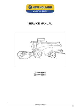
  • 1. SERVICE MANUAL CX5000 series CX6000 series 84386774A 11/05/2011 EN
  • 2. Contents INTRODUCTION HYDRAULIC, PNEUMATIC, ELECTRICAL, ELECTRONIC SYSTEMS A PRIMARY HYDRAULIC POWER SYSTEM.............................................. A.10.A PNEUMATIC SYSTEM ................................................................... A.20.A ELECTRICAL POWER SYSTEM ........................................................ A.30.A ELECTRONIC SYSTEM ................................................................. A.50.A FAULT CODES ........................................................................... A.50.A ENGINE AND PTO IN ................................................................... B EXHAUST SYSTEM Emissions control .................................................. B.40.B TRANSMISSION, DRIVE AND PTO OUT........................................ C TRANSMISSION Mechanical ............................................................ C.20.B TRANSMISSION Hydrostatic............................................................. C.20.F PROCESS DRIVE Primary process drive ................................................ C.50.B AXLES, BRAKES AND STEERING................................................. D FRONT AXLE ............................................................................ D.10.A REAR AXLE .............................................................................. D.12.A 2WD-4WD SYSTEM Hydrostatic......................................................... D.14.E STEERING Hydraulic..................................................................... D.20.C STEERING Mechanical .................................................................. D.20.B SERVICE BRAKE Hydraulic.............................................................. D.30.C PARKING BRAKE Mechanical ........................................................... D.32.B FRAME AND CAB ........................................................................ E USER PLATFORM ....................................................................... E.34.A ENVIRONMENT CONTROL Heating system ............................................ E.40.B ENVIRONMENT CONTROL Air-conditioning system .................................... E.40.C FRAME POSITIONING ................................................................. F FRAME LEVELLING ..................................................................... F.30.A TOOL POSITIONING.................................................................... G 84386774A 11/05/2011
  • 3. LIFTING .................................................................................. G.10.A LEVELLING .............................................................................. G.30.A CROP PROCESSING ................................................................... K FEEDING Reel feeding................................................................... K.25.B FEEDING Header feeding................................................................ K.25.D FEEDING Feeder housing ............................................................... K.25.E THRESHING Conventional threshing .................................................... K.40.B SEPARATING Beating.................................................................... K.42.B SEPARATING Rotary separator.......................................................... K.42.C SEPARATING Straw flow beater ......................................................... K.42.F SEPARATING Straw walker .............................................................. K.42.E CLEANING Primary cleaning............................................................. K.62.B CLEANING Tailings return system ....................................................... K.62.C STORING AND HANDLING Grain storing ............................................... K.60.B UNLOADING Grain unloading............................................................ K.72.B 84386774A 11/05/2011
  • 5. INTRODUCTION Foreword IMPORTANT INFORMATION All repair and maintenance works listed in this manual must be carried out only by staff belonging to the NEW HOL- LAND Service network, strictly complying with the instructions given and using, whenever required, the special tools. Anyone who carries out the above operations without complying with the prescriptions shall be responsible for the subsequent damages. The manufacturer and all the organizations of its distribution chain, including - without limitation - national, regional or local dealers, reject any responsibility for damages due to the anomalous behavior of parts and/or components not approved by the manufacturer himself, including those used for the servicing or repair of the product manufactured or marketed by the Manufacturer. In any case, no warranty is given or attributed on the product manufactured or marketed by the Manufacturer in case of damages due to an anomalous behavior of parts and/or components not approved by the Manufacturer. No reproduction, though partial of text and illustrations allowed 84386774A 11/05/2011 3
  • 6. INTRODUCTION Foreword Technical Information This manual has been produced by a new technical information system. This new system is designed to deliver technical information electronically through CD-ROM and in paper manuals. A coding system called ICE has been developed to link the technical information to other Product Support functions e.g. Warranty. Technical information is written to support the maintenance and service of the functions or systems on a customers machine. When a customer has a concern on his machine it is usually because a function or system on his machine is not working at all, is not working efficiently, or is not responding correctly to his commands. When you refer to the technical information in this manual to resolve that customers concern, you will find all the information classified using the new ICE coding, according to the functions or systems on that machine. Once you have located the technical information for that function or system then you will find all the mechanical, electrical or hydraulic devices, compo- nents, assemblies and sub assemblies for that function or system. You will also find all the types of information that have been written for that function or system, the technical data (specifications), the functional data (how it works), the diagnostic data (fault codes and troubleshooting) and the service data (remove, install adjust, etc.). By integrating this new ICE coding into technical information , you will be able to search and retrieve just the right piece of technical information you need to resolve that customers concern on his machine. This is made possible by attaching 3 categories to each piece of technical information during the authoring process. The first category is the Location, the second category is the Information Type and the third category is the Product: • LOCATION - is the component or function on the machine, that the piece of technical information is going to describe e.g. Fuel tank. • INFORMATION TYPE - is the piece of technical information that has been written for a particular component or function on the machine e.g. Capacity would be a type of Technical Data that would describe the amount of fuel held by the Fuel tank. • PRODUCT - is the model that the piece of technical information is written for. Every piece of technical information will have those 3 categories attached to it. You will be able to use any combination of those categories to find the right piece of technical information you need to resolve that customers concern on his machine. That information could be: • the description of how to remove the cylinder head • a table of specifications for a hydraulic pump • a fault code • a troubleshooting table • a special tool 84386774A 11/05/2011 4
  • 7. INTRODUCTION How to Use this Manual This manual is divided into Sections. Each Section is then divided into Chapters. Contents pages are included at the beginning of the manual, then inside every Section and inside every Chapter. An alphabetical Index is included at the end of a Chapter. Page number references are included for every piece of technical information listed in the Chapter Contents or Chapter Index. Each Chapter is divided into four Information types: • Technical Data (specifications) for all the mechanical, electrical or hydraulic devices, components and, assem- blies. • Functional Data (how it works) for all the mechanical, electrical or hydraulic devices, components and assem- blies. • Diagnostic Data (fault codes, electrical and hydraulic troubleshooting) for all the mechanical, electrical or hy- draulic devices, components and assemblies. • Service data (remove disassembly, assemble, install) for all the mechanical, electrical or hydraulic devices, components and assemblies. Sections Sections are grouped according to the main functions or a systems on the machine. Each Section is identified by a letter A, B, C etc. The amount of Sections included in the manual will depend on the type and function of the machine that the manual is written for. Each Section has a Contents page listed in alphabetic/numeric order. This table illustrates which Sections could be included in a manual for a particular product. SECTION A - Distribution Systems B - Power Production C - Power Train D - Travelling E - Body and Structure F - Frame Positioning G - Tool Positioning H - Working Arm J - Tools and Couplers K - Crop Processing L - Field Processing PRODUCT Tractors X X X X X X X X Vehicles with working arms: backhoes, excavators, skid steers, ..... X X X X X X X X X Combines, forage harvesters, balers, .... X X X X X X X X X X Seeding, planting, floating, spraying equipment, .... X X X X X X X X X Mounted equipment and tools, ..... X X X X 84386774A 11/05/2011 5
  • 8. INTRODUCTION This manual contains these Sections. The contents of each Section are explained over the following pages. Contents INTRODUCTION DISTRIBUTION SYSTEMS A POWER PRODUCTION B POWER TRAIN C TRAVELLING D BODY AND STRUCTURE E TOOL POSITIONING G CROP PROCESSING K Section Contents SECTION A, DISTRIBUTION SYSTEMS This Section covers the main systems that interact with most of the functions of the product. It includes the central parts of the hydraulic, electrical, electronic, pneumatic, lighting and grease lubrication systems. The components that are dedicated to a specific function are listed in the Chapter where all the technical information for that function is included. SECTION B, POWER PRODUCTION This Section covers all the functions related to the production of power to move the machine and to drive various devices. SECTION C, POWER TRAIN This Section covers all the functions related to the transmission of power from the engine to the axles and to internal or external devices and additional Process Drive functions. SECTION D, TRAVELLING This Section covers all the functions related to moving the machine, including tracks, wheels, steering and braking. It covers all the axles both driven axles and non-driven axles, including any axle suspension. SECTION E, BODY AND STRUCTURE This Section covers all the main functions and systems related to the structure and body of the machine. Including the frame, the shields, the operator's cab and the platform. SECTION G, TOOL POSITIONING This Section covers all the functions related to the final and/or automatic positioning of the tool once the tool is posi- tioned using the Working Arm or the machine frame. SECTION K, CROP PROCESSING This Section covers all the functions related to crop processing. 84386774A 11/05/2011 6
  • 9. SERVICE MANUAL HYDRAULIC, PNEUMATIC, ELECTRICAL, ELECTRONIC SYSTEMS CX5000 series CX6000 series 84386774A 11/05/2011 A
  • 10. HYDRAULIC, PNEUMATIC, ELECTRICAL, ELECTRONIC SYSTEMS - PRIMARY HYDRAULIC POWER SYSTEM PRIMARY HYDRAULIC POWER SYSTEM - Torque Union nuts 55009 1 Ferrules The ferrule must be pre-assembled on the tube. Tighten the union nut as specified in the table below. The ferrule and screw thread are greased. Torque Nm (lb.ft)Tube outer diameter mm (inch) Minimum Maximum 8 (0.32) 15 (11) 20 (15) 10 (0.4) 25 (18) 30 (22) 12 (0.47) 35 (26) 40 (29) 16 (0.63) 50 (37) 55 (40) 18 (0.71) 60 (44) 70 (51) 22 (0.87) 100 (74) 110 (81) 28 (1.10) 110 (81) 120 (88) Metric fittings Unions Are suitable for use with union nuts and ferrules and ball-type nipples. 55011 2 84386774A 11/05/2011 A.10.A / 3
  • 11. HYDRAULIC, PNEUMATIC, ELECTRICAL, ELECTRONIC SYSTEMS - PRIMARY HYDRAULIC POWER SYSTEM Connections Are screwed in ISO metric thread - tolerance class 6H - with a tightening torque as specified in the table below. 55012 3 Torque Nm (lb.ft)Tube outer diameter mm (inch) Minimum Maximum 8 (0,32) 40 (29) 45 (33) 10 (0,40) 65 (48) 70 (51) 12 (0,47) 80 (59) 85 (63) 16 (0,63) 100 (74) 120 (88) 18 (0,71) 120 (88) 140 (103) 22 (0,87) 200 (147) 220 (164) 28 (1,10) 350 (257) 380 (280) Swivel nut with ball-type nipple Are suitable for use with female unions 55013 4 D1 Torque Nm (lb.ft) 6H Minimum Maximum M14 x 1.5 - - M16 x 1.5 15 (11) 20 (15) M18 x 1.5 20 (15) 25 (18) M24 x 1.5 30 (22) 35 (26) M26 x 1.5 - - M30 x 2 - - M36 x 2 - - 84386774A 11/05/2011 A.10.A / 4
  • 12. HYDRAULIC, PNEUMATIC, ELECTRICAL, ELECTRONIC SYSTEMS - PRIMARY HYDRAULIC POWER SYSTEM Hydraulic pump - General specification The hydraulic system contains three hydraulic pumps ZDF0052A 1 Main hydraulic pump (2) Type: Silence gear type Direction of rotation left-hand rotation Maximum pressure 280 bar ( 4061 psi) Maximum speed 3000 rpm Output per revolution 16.5 cc/rev. Maximum oil flow 48 l/min ( 12.7 gal/min) Hydraulic pump (Steering circuit) (3) Type: Silence gear type Direction of rotation left-hand rotation Maximum pressure 280 bar ( 4061 psi) Maximum speed 3000 rpm Output per revolution 5.5 cc/rev. Maximum oil flow 12 l/min ( 3.2 gal/min) Hydraulic pump (Lateral flotation circuit) (4) (if installed) Type: Gear type Direction of rotation left-hand rotation Maximum pressure 230 bar ( 3336 psi) Maximum speed 3000 rpm Output per revolution 2 cc/rev. Maximum oil flow 6 l/min ( 1.6 gal/min) 84386774A 11/05/2011 A.10.A / 5
  • 13. HYDRAULIC, PNEUMATIC, ELECTRICAL, ELECTRONIC SYSTEMS - PRIMARY HYDRAULIC POWER SYSTEM PRIMARY HYDRAULIC POWER SYSTEM - Hydraulic schema 1. Engine 20. Reel horizontal adjustment cylinders 2. Pump (main hydraulics) 21. Header and straw elevator reversing valve 3. Pump (steering circuit) 22. Screw couplers with non return valve 4. Pump (lateral flotation) (If installed) 23. Header and straw elevator reversing motor 5. Oil reservoir 24. Steering valve 6. Filler cap with filter 25. Steering cylinder(s) 7. Load sensing valve 27. Load sensing valve 8. Header height control valve 28. Lateral flotation control valve 9. Header cylinders 29. Lateral flotation cylinder 10. Accumulator control valve 30. Lateral float minimum pressure valve ( 60 bar) 11. Header suspension accumulator 30 a. Lateral float accumulator ( 120 bar) 12. Pressure sensor 30 b. Lateral float accumulator ( 85 bar) 13. Unloading tube control valve 31. Drain hose 14. Unloading tube cylinder 32. Low pressure filter 15. Reel vertical adjustment valve 33. Breather with filter and non-return valve 16. Reel vertical adjustment cylinders P. Inlet (high pressure) 17. Reel horizontal adjustment valve R. Return (low pressure) 18. Quick-attach coupler - - - Pilot line, load sensing line 19. Non-return valve (single direction restrictor) 42. Pilot valve P1. P1 = 140 bar for adjustable steering axle (A.S.A.). P1 = 160 bar for fixed or powered rear axle. P2. P2 = 200 bar for adjustable steering axle (A.S.A.). P1 = 220 bar for fixed or powered rear axle. 84386774A 11/05/2011 A.10.A / 6
  • 14. HYDRAULIC, PNEUMATIC, ELECTRICAL, ELECTRONIC SYSTEMS - PRIMARY HYDRAULIC POWER SYSTEM PRIMARY HYDRAULIC POWER SYSTEM - Overview ZEIL11CX0660F0B 1 ZEIL11CX0661F0B 2 84386774A 11/05/2011 A.10.A / 12
  • 15. HYDRAULIC, PNEUMATIC, ELECTRICAL, ELECTRONIC SYSTEMS - PRIMARY HYDRAULIC POWER SYSTEM PRIMARY HYDRAULIC POWER SYSTEM - Component localisation NOTE: To find the location of those components, refer to PRIMARY HYDRAULIC POWER SYSTEM - Overview (A.10.A) FRONT Header Header quick-release coupler (18) ZDA6003C 1 Lateral float cylinder (29) (if lateral float installed) RNIL08CS0002A0B 2 Straw elevator Header lift cylinders (9) ZDA5998C 3 84386774A 11/05/2011 A.10.A / 13
  • 16. HYDRAULIC, PNEUMATIC, ELECTRICAL, ELECTRONIC SYSTEMS - PRIMARY HYDRAULIC POWER SYSTEM Lateral float accumulator ( 120 bar) (30a) Lateral float accumulator ( 85 bar) (30b) ZEIL06CS0141A0B 4 Screw couplers with non return valve (22) Header and straw elevator reversing motor (23) ZDA6258B 5 Under cab Steering valve (24) ZDA7538A 6 84386774A 11/05/2011 A.10.A / 14
  • 17. HYDRAULIC, PNEUMATIC, ELECTRICAL, ELECTRONIC SYSTEMS - PRIMARY HYDRAULIC POWER SYSTEM LEFT-HAND SIDE Cab left Load sensing valve (7) Header height control valve (8) Unloading tube control valve (13) Reel vertical adjustment valve (15) Reel horizontal adjustment valve (17) Header and straw elevator reversing valve (21) Load sensing valve (27) Lateral flotation control valve (28) Lateral float minimum pressure valve ( 60 bar) (30) RNPH08CS0008A0B 7 Above front wheel Unload tube cylinder (14) ZEIL11CX0662A0B 8 Straw elevator and header engaging cylinder (37) ZEIL11CX0663A0B 9 Unloading engaging cylinder (41) ZEIL11CX0664A0B 10 84386774A 11/05/2011 A.10.A / 15
  • 18. HYDRAULIC, PNEUMATIC, ELECTRICAL, ELECTRONIC SYSTEMS - PRIMARY HYDRAULIC POWER SYSTEM Middle Drain hose (31) ZEIL10CX0188A0Z 11 Above Threshing engaging clutch (34) Rotary union (35) ZEIL06CS0092A0C 12 84386774A 11/05/2011 A.10.A / 16
  • 19. HYDRAULIC, PNEUMATIC, ELECTRICAL, ELECTRONIC SYSTEMS - PRIMARY HYDRAULIC POWER SYSTEM ABOVE Oil reservoir (5) Filler cap with filter (6) Breather with filter and non-return valve (33) Low pressure filter (32) ZEIL10CX0191A0Z 13 Main hydraulic pump (2) Pump (3) (Steering circuit) Pump (4) (Lateral flotation) ZEIL06CS0150A0B 14 UNDER Above front axle Header suspension accumulator (11) Pressure sensor (12) RNIL08CS0005A0B 15 At the back Steering cylinder(s) (25) ZDA7540A 16 84386774A 11/05/2011 A.10.A / 17
  • 20. HYDRAULIC, PNEUMATIC, ELECTRICAL, ELECTRONIC SYSTEMS - PRIMARY HYDRAULIC POWER SYSTEM Stack valve - Dynamic description If all valves are in the "0" position, then: The valves (13), (15), (17), (21) and (28), (Refer to Stack valve - Static description (A.10.A)) are closed, which means that the oil can not flow through these valves. The pressure raises at (7b), (27b), until the load sensing spool is pushed open against spring pressure (delta P= 3 bar) and the return pressure in the pilot line (7a), (27a). Now pump oil flows into the return line at standby pressure. When activating the lateral float control spools (if installed), the hydraulic cylinder pressure (pump pressure measured after the spool restriction) is present in the pilot line (7a), (27a) and closes the load sensing spool. The oil pressure is available for the activated control spool(s). When the pump pressure reaches the cylinder pressure (+ 3 bar), the load sensing spool is pushed open. The nec- essary amount of oil will flow to the control spool at the needed pressure. Excess oil is dumped into the return line. When activating valves without direct load sensing, (13), (15), (17) and (21), the pilot valve (42) is activated as well to connect the pressure line with the load sensing line and closes the load sensing spool. The oil pressure is available for the activated control spool(s). When the pump pressure reaches the cylinder pressure (+ 3 bar), the load sensing spool is pushed open. The nec- essary amount of oil will flow to the control spool at the needed pressure. Excess oil is dumped into the return line. When the cylinder reaches end of stroke, the system pressure starts to raise. When the pilot pressure reaches 207 bar for the main stack valve ( 175 bar for the lateral float stack valve) the pressure relief valve is pushed open and system pressure is limited to 210 bar (207 + 3 bar) The load sensing lockout valve ensures that pilot pressure cannot escape into the return. RNPH08CS0008A0B 1 84386774A 11/05/2011 A.10.A / 18
  • 21. HYDRAULIC, PNEUMATIC, ELECTRICAL, ELECTRONIC SYSTEMS - PRIMARY HYDRAULIC POWER SYSTEM Operation of reversing system valve (21). In neutral position of the valve, both motor connections are connected to each other by the return system. When switching the valve to position “1" or “2", the pilot valve (42) is activated as well to connect the pressure line with the load sensing line and closes the load sensing spool. Full oil flow is available towards the hydraulic motor. RNPH08CS0008A0B 2 Operation of the reel vertical adjustment valve (15). When switching this valve, the pilot valve (42) is activated as well to connect the pressure line with the load sensing line and closes the load sensing spool. Full oil flow is available towards the hydraulic cylinder. These valves are connected to a single-acting cylinder which means that only one lockout valve is provided in the connection towards the cylinder. RNPH08CS0008A0B 3 Operation of the unloading tube control valve (13) and the reel horizontal adjustment valve (17). When switching one of these valves, the pilot valve (42) is activated as well to connect the pressure line with the load sensing line and closes the load sensing spool. Full oil flow is available towards the hydraulic cylinder. Lockout valves are installed in the connections towards the cylinder. RNPH08CS0008A0B 4 84386774A 11/05/2011 A.10.A / 19
  • 22. Thank you very much for your reading. Please Click Here. Then Get COMPLETE MANUAL. NO WAITING NOTE: If there is no response to click on the link above, please download the PDF document first and then click on it.
  • 23. HYDRAULIC, PNEUMATIC, ELECTRICAL, ELECTRONIC SYSTEMS - PRIMARY HYDRAULIC POWER SYSTEM Stack valve - Static description The main hydraulic system will be a open centre load sensing system that controls all high pressure functions: All header functions and unloading auger swing. The hydraulic system contains one stack valve: • Main stack valve . (see also hydraulic schematic PRIMARY HYDRAULIC POWER SYSTEM - Hydraulic schema (A.10.A)) Located at the left-hand side of the cab behind the steering platform. RNPH08CS0008A0B 1 The stack valve consists of two main parts. • Control valves for oil supply and load sensing (7 and 27) Refer to PRIMARY HYDRAULIC POWER SYSTEM - Hydraulic schema (A.10.A) Load sensing is a system which avoids high pressure when the valves are in neutral position and consequently, less heating up of the oil and creating load-independent flow rate control. • Control valves with load sensing (13-15-17-21-28) Refer to PRIMARY HYDRAULIC POWER SYSTEM - Hydraulic schema (A.10.A). RNPH08CS0008A0B 2 13 Unloading tube movement 15 Reel vertical adjustment 17 Reel horizontal adjustment 21 Reversing system 28 Lateral float system 84386774A 11/05/2011 A.10.A / 20
  • 24. HYDRAULIC, PNEUMATIC, ELECTRICAL, ELECTRONIC SYSTEMS - PRIMARY HYDRAULIC POWER SYSTEM Hydraulic pump - Exploded view ZDF0842A 1 Main hydraulic pump 1 Pump housing 2 Bearing end plate 3 Radial-lip-type oil seal 4 Retaining ring 5 Housing cover 6 Toothed washer 7 Toothed gear 8 Toothed gear 9 Woodruff key 10 Hexagon nut 11 Spring lock washer 12 Protective cap 13 Protective cap 14 Bushing 15 Bushing 16 Head screw 17 Straight pin 18 Straight pin 19 Set of seals NOTE: Tighten the screw (16) with a torque between 12 - 16 Nm. ( 9 - 12 lb ft) 84386774A 11/05/2011 A.10.A / 21
  • 25. HYDRAULIC, PNEUMATIC, ELECTRICAL, ELECTRONIC SYSTEMS - PRIMARY HYDRAULIC POWER SYSTEM Filter - Static description The low pressure filter (32) is installed on top of the hydraulic reservoir (5) and has a bypass (non-return) valve set to 1.15 bar ( 17 psi). The return oil from the hydraulics system is flowing through the low pressure filter before entering the hydraulic oil reservoir. ZEIL10CX0191A0Z 1 84386774A 11/05/2011 A.10.A / 22
  • 26. HYDRAULIC, PNEUMATIC, ELECTRICAL, ELECTRONIC SYSTEMS - PRIMARY HYDRAULIC POWER SYSTEM Breather - Static description The breather (33) allows the air in the reservoir to escape whenever a considerable oil flow arrives at the reservoir (e.g. when lowering the attachment). ZEIL10CX0191A0Z 1 84386774A 11/05/2011 A.10.A / 23