SlideShare a Scribd company logo
1 of 18
Download to read offline
T4020 Deluxe - T4020 Supersteer - T4030 Deluxe -
T4030 Supersteer - T4040 Deluxe - T4040 Supersteer -
T4050 Deluxe - T4050 Supersteer TRACTORS
SERVICE MANUAL
SECTIONS
GENERAL GUIDELINES 00
. . . . . . . . . . . . . . . . . . . . . . . . . . . . . . . . . . . . . . . . . . . . . . . . . . . . .
ENGINE 10
. . . . . . . . . . . . . . . . . . . . . . . . . . . . . . . . . . . . . . . . . . . . . . . . . . . . . . . . . . . . . . . . . . . .
CLUTCH 18
. . . . . . . . . . . . . . . . . . . . . . . . . . . . . . . . . . . . . . . . . . . . . . . . . . . . . . . . . . . . . . . . . . . .
TRANSMISSIONS 21
. . . . . . . . . . . . . . . . . . . . . . . . . . . . . . . . . . . . . . . . . . . . . . . . . . . . . . . . . . .
DRIVE LINES 23
. . . . . . . . . . . . . . . . . . . . . . . . . . . . . . . . . . . . . . . . . . . . . . . . . . . . . . . . . . . . . . .
FRONT MECHANICAL TRANSMISSION 25
. . . . . . . . . . . . . . . . . . . . . . . . . . . . . . . . . . . . . . .
REAR MECHANICAL TRANSMISSION 27
. . . . . . . . . . . . . . . . . . . . . . . . . . . . . . . . . . . . . . . .
POWER TAKE-OFF 31
. . . . . . . . . . . . . . . . . . . . . . . . . . . . . . . . . . . . . . . . . . . . . . . . . . . . . . . . .
BRAKES 33
. . . . . . . . . . . . . . . . . . . . . . . . . . . . . . . . . . . . . . . . . . . . . . . . . . . . . . . . . . . . . . . . . . . .
HYDRAULIC SYSTEMS 35
. . . . . . . . . . . . . . . . . . . . . . . . . . . . . . . . . . . . . . . . . . . . . . . . . . . . . .
STEERING 41
. . . . . . . . . . . . . . . . . . . . . . . . . . . . . . . . . . . . . . . . . . . . . . . . . . . . . . . . . . . . . . . . . .
AXLE AND WHEELS 44
. . . . . . . . . . . . . . . . . . . . . . . . . . . . . . . . . . . . . . . . . . . . . . . . . . . . . . . . .
CAB AIR CONDITIONING SYSTEM 50
. . . . . . . . . . . . . . . . . . . . . . . . . . . . . . . . . . . . . . . . . . .
ELECTRICAL SYSTEM 55
. . . . . . . . . . . . . . . . . . . . . . . . . . . . . . . . . . . . . . . . . . . . . . . . . . . . . . .
PLATFORM, CAB, BODYWORK 90
. . . . . . . . . . . . . . . . . . . . . . . . . . . . . . . . . . . . . . . . . . . . . .
T E C H N I C A L S U P P O R T
INTRODUCTORY NOTES
- This manual is divided into sections identified by two-figure numbers and each section has independent
page numbering.
- The different sections can easily be found by consulting the table of contents on the following pages.
- The document number of the manual and the edition/update dates are given at the bottom of each page.
- Pages updated in the future will be identified by the same document number followed by an additional digit:
first edition standard manual 87666787A - 1st update 87666787A1 - 2nd update 87666787A2 - etc.
The update pages can replace or supplement the pages of the standard manual; the information necessary
for the procedure for adding or replacing pages is given on the title page of the update.
The publication will be completed with an appropriate index.
If it is necessary to issue a new updated manual (2nd edition) it will have document number 87666787B, this
indicates that the manual is composed of the standard version 87666787A completed with all the updates:
1st update 87666787A1 - 2nd update 87666787A2 - etc.
- The information contained in this manual was current on the date printed on each section. As
NEWHOLLAND constantly improves its product range, some information may be out of date subsequent
to modifications implemented for technical or commercial reasons, or to meet legal requirements in different
countries.
In the event of conflicting information, consult the NEW HOLLAND Sales and Service Departments.
IMPORTANT WARNINGS
- All maintenance and repair work described in this manual must be performed exclusively by NEW HOLLAND
service technicians, in strict accordance with the instructions given and using any specific tools necessary.
- Anyone performing the operations described herein without strictly following the instructions is personally
responsible for any eventual injury or damage to property.
- The Manufacturer and all organisations belonging to the Manufacturer's distribution network, including but
not restricted to national, regional or local distributors, will accept no responsibility for personal injury or
damage to property caused by abnormal function of parts and/or components not approved by the
Manufacturer, including those used for maintenance and/or repair of the product manufactured or marketed
by the Manufacturer.
In any case, the product manufactured or marketed by the Manufacturer is covered by no guarantee of any
kind against personal injury or damage to property caused by abnormal function of parts and/or components
not approved by the Manufacturer.
No part of the text or illustrations
may be reproduced
PRINTED IN FRANCE
© CNH GLOBAL N.V.
Print No. 87666787A1 - 03 - 2008
CONTENT 3
87666787A2 − 06 − 2009
CONTENT
Page Date
00 − GENERAL GUIDELINES
General instructions . . . . . 1−2 11−07
Safety regulations . . . . . . . 3−4−5 11−07
Tractor refuelling . . . . . . . . 6 11−07
10 − ENGINE
CHAPTER 1 − Engine T4040 and T4050
models
Summary . . . . . . . . . . . . . . . 1 11−07
General specifications . . . . 2−3−4 11−07
Fuel system data . . . . . . . . 4 11−07
Engine block data . . . . . . . 5 11−07
Crankshaft data . . . . . . . . . 5 11−07
Connecting rod data . . . . . 6 11−07
Piston data . . . . . . . . . . . . . 6−7 11−07
Timing gear data . . . . . . . . 7 11−07
Cylinder head data . . . . . . 8−9 11−07
Tightening torques . . . . . . . 10−11 11−07
Tools . . . . . . . . . . . . . . . . . . 12 11−07
Engine diagrams . . . . . . . . 13 11−07
Lubrication diagrams . . . . . 14 11−07
Cooling diagram . . . . . . . . . 15 11−07
Additional counterweight
diagrams . . . . . . . . . . . . . . . 16 11−07
Exhaust gas recirculation
system (EGR) . . . . . . . . . . . 17 11−07
Fault finding . . . . . . . . . . . . 18−19−20−
21 11−07
Engine removal−installa-
tion . . . . . . . . . . . . . . . . . . . . 22−23−24−
25−26−27−
28−29−30−
31−32 11−07
Page Date
Engine disassembly−
assembly . . . . . . . . . . . . . . . 33−34−35−
36−37−38−
39−40−41−
42−43−44−
45−46−47−
48−49−50−
51−52−53−
54−55−56−
57−58−59−
60−61−62−
63−64−65−
66 11−07
Checks and measurements
− cylinder block and liners
67−68−69 11−07
Checks and measurements
− crankshaft, bearings and
flywheel . . . . . . 70−71 11−07
Checks and measurements
− connecting rods . . . . . . . 72−73 11−07
Checks and measurements
− pistons . . . . . 74−75−76−
77 11−07
Checks and measurements
− camshaft, tappets and
valves . . . . . . . . . . . . . . . . . 78−79−80−
81 11−07
Checks and measurements
− cylinder head 82 11−07
Checks and measurements
− lubrication system . . . . . . 83 11−07
Checks and measurements
− cooling system . . . . . . . . 84 11−07
Removal−Installation −
crankshaft front seal . . . . . 85−86 11−07
Replacing crankshaft rear
seal . . . . . . . . . . . . . . . . . . . 87−88−89 11−07
Valve clearance adjustment
. . . . . . . . . . . . . . 90−91 11−07
Removal−Installation − in-
jectors . . . . . . . . . . . . . . . . . 92−93−94 11−07
Removal − Installation −
Bosch injection pump . . . . 95−96−97 11−07
Bosch injection pump − tim-
ing . . . . . . . . . . . . . . . . . . . . 98−99−100 11−07
Bosch injection pump − air
bleeding . . . . . . . . . . . . . . . . 100 11−07
4 CONTENT
87666787A2 − 06 − 2009
Page Date
Removal−Installation −
coolant pump . . . . . . . . . . . 101−102 11−07
Removal−Installation −
thermostat valve . . . . . . . . . 103−104 11−07
Removal−Installation −
radiator . . . . . . . . . . . . . . . .
105−106−
107−108 11−07
Coolant pump and gener-
ator drive belt . . . . . . . . . . . 109−110 11−07
CHAPTER 2 − Engine T4020 and
T4030 models
Summary . . . . . . . . . . . . . . . 1 03−08
General specifications . . . . 2−3 03−08
Engine removal−installa-
tion . . . . . . . . . . . . . . . . . . . . 4−5−6−7−8
−9−10−11−
12−13−14−
15−16−17 03−08
18 − CLUTCH
Data . . . . . . . . . . . . . . . . . . . 1−2 11−07
Tightening torques . . . . . . . 2 11−07
Tools . . . . . . . . . . . . . . . . . . 2−3 11−07
Sections . . . . . . . . . . . . . . . 3−4 11−07
Fault finding . . . . . . . . . . . . 5 11−07
Removal−Installation −
clutch . . . . . . . . . . . . . . . . . . 6−7−8−9−
10−11−12−
13−14−15 11−07
Clutch Overhaul . . . . . . . . . 16−17−18−
19−20 11−07
Checks and measurements
− clutch . . . . . . . . . . . . . . . . 21−22 11−07
Adjustments − clutch disen-
gagement levers . . . . . . . . 22−23 11−07
Adjustments − clutch pedal 24 11−07
PTO control adjustment . . 25 11−07
Sectional view of PTO
clutch servo control . . . . . . 26 11−07
Description and operation
of PTO servo control . . . . . 27−28 11−07
PTO servo control adjust-
ment . . . . . . . . . . . . . . . . . . . 29 11−07
PTO engaged switch ad-
justment . . . . . . . . . . . . . . . . 30 11−07
Page Date
21 − TRANSMISSIONS
CHAPTER 1 − Transmission and range gear
(16x16)
Data . . . . . . . . . . . . . . . . . . . 1−2 11−07
Tightening torques . . . . . . . 2−3 11−07
Tools . . . . . . . . . . . . . . . . . . 4−5−6−7 11−07
Sections . . . . . . . . . . . . . . . 8−9−10−11 11−07
Description and operation 12 11−07
Fault finding . . . . . . . . . . . . 12−13 11−07
Removal−Installation −
rear transmission − gear-
box casing . . . . . . . . . . . . . . 14−15−16−
17−18−19−
20 11−07
Disassembly−Assembly −
transmission−gearbox cas-
ing . . . . . . . . . . . . . . . . . . . . 21−22−23−
24−25−26−
27−28 11−07
Gearbox driving and driven
shafts end float adjustment 29 11−07
Sealing compound applica-
tion diagram . . . . . . . . . . . . 30 11−07
Gearbox control lever. Re-
moval − Installation . . . . . . 31 11−07
Range gear control lever.
Removal − Installation . . . . 32 11−07
Shuttle control lever. Re-
moval − Installation . . . . . . 33 11−07
Fuel tank. Removal − In-
stallation . . . . . . . . . . . . . . . 34−35 11−07
CHAPTER 2 − Mechanical transmission and
splitter
Data . . . . . . . . . . . . . . . . . . . 1−2 11−07
Tightening torques . . . . . . . 2 11−07
Tools . . . . . . . . . . . . . . . . . . 2 11−07
Sections . . . . . . . . . . . . . . . 3−4−5 11−07
Description and operation . 6 11−07
Fault finding . . . . . . . . . . . . 7 11−07
Splitter device and creeper
unit casing, shafts and
bearings disassembly . . . . 8−9−10 11−07
CONTENT 5
87666787A2 − 06 − 2009
Page Date
CHAPTER 3 − Power Shuttle transmission
with dual command (2 Speed Power Shift)
function
Data . . . . . . . . . . . . . . . . . . . 1−2 11−07
Tightening torques . . . . . . . 3 11−07
Tools . . . . . . . . . . . . . . . . . . 4−5−6 11−07
Sections . . . . . . . . . . . . . . . 7−8−9−10−
11 11−07
Clutch control pressure test 10 11−07
Description and operation . 12 11−07
Fault finding . . . . . . . . . . . . 12 11−07
Disassembly−Assembly −
transmission−gearbox cas-
ing . . . . . . . . . . . . . . . . . . . . 13−14 11−07
Disassembly−Reassembly
− Power Shuttle control
valve . . . . . . . . . . . . . . . . . . 15−16−17 11−07
Disassembly−Assembly −
accumulator . . . . . . . . . . . . 18 11−07
Gearbox control valve sole-
noid valve. Removal − In-
stallation . . . . . . . . . . . . . . . 19−20 11−07
Disassembly−Assembly −
clutch casing . . . . . . . . . . . . 21−22−23−
24 11−07
CHAPTER 4 − Power Shuttle transmission
(16 + 16 and 8 + 8 versions)
Data . . . . . . . . . . . . . . . . . . . 1 11−07
Tightening torques . . . . . . . 2 11−07
Sections . . . . . . . . . . . . . . . 3−4−5−6 11−07
Clutch control pressure test 6 11−07
23 − DRIVE LINES
Data . . . . . . . . . . . . . . . . . . . 1 11−07
Tightening torques . . . . . . . 2 11−07
Tools . . . . . . . . . . . . . . . . . . 3−4 11−07
Sections . . . . . . . . . . . . . . . 5−6−7 11−07
Description and operation . 8−9 11−07
Fault finding . . . . . . . . . . . . 9 11−07
Drive shafts and guard.
Disassembly− Assembly . . 10−11−12 11−07
Removal−Installation −
drive gear casing . . . . . . . . 13−14 11−07
Page Date
Disassembly−Assembly −
drive gear casing . . . . . . . . 15−16−17−
18 11−07
25 − FRONT AXLE MECHANICAL
TRANSMISSION
CHAPTER 1 − Front mechanical
transmission (mod. T4040 Supersteer
and T4050 Supersteer)
Data . . . . . . . . . . . . . . . . . . . 1−2−3 11−07
Tightening torques . . . . . . . 4−5−6 11−07
Tools . . . . . . . . . . . . . . . . . . 7−8−9 11−07
Sections . . . . . . . . . . . . . . . 10−11−12−
13 11−07
Description and operation 13−14 11−07
Fault finding . . . . . . . . . . . . 15 11−07
Removal−Installation −
front axle . . . . . . . . . . . . . . . 16−17−18−
19 11−07
Removal−Installation −
front axle differential and
bevel drive support . . . . . . 20−21−22−
23 11−07
Overhaul − front axle bevel
drive . . . . . . . . . . . . . . . . . . . 24−25 11−07
Adjustments − bevel drive 26−27−28−
29−30−31 11−07
Overhaul − front differential 32 11−07
Overhaul − differential lock
unit . . . . . . . . . . . . . . . . . . . . 33−34−35 11−07
Disassembly−Assembly −
front epicyclic final drive
with brake . . . . . . . . . . . . . . 36−37−38−
39 11−07
Disassembly−Assembly −
front epicyclic final drive . . 40−41−42 11−07
Wheel hub seal. Renew . . 43 11−07
Wheel hub and steering
knuckle. Disassembly− As-
sembly . . . . . . . . . . . . . . . . . 44 11−07
Adjustments − steering
knuckle bearings . . . . . . . . 45 11−07
Replacing steering knuckle
pins and bearings . . . . . . . 46 11−07
Lead−drive wheel position
check . . . . . . . . . . . . . . . . . . 47 11−07
6 CONTENT
87666787A2 − 06 − 2009
Page Date
CHAPTER 2 − Front mechanical transmission
(mod. T4040 Deluxe and T4050 Deluxe)
Data . . . . . . . . . . . . . . . . . . . 1−2 11−07
Tightening torques . . . . . . . 3−4 11−07
Tools . . . . . . . . . . . . . . . . . . 5−6 11−07
Sections . . . . . . . . . . . . . . . 7−8 11−07
Description and operation 8−9 11−07
Fault finding . . . . . . . . . . . . 10 11−07
Removal−Installation −
front axle . . . . . . . . . . . . . . . 11−12−13−
14 11−07
Front axle. Disassembly−
Assembly . . . . . . . . . . . . . . 15−16−17−
18−19−20−
21−22−23 11−07
Overhaul − differential lock
unit . . . . . . . . . . . . . . . . . . . . 24−25 11−07
Replacing steering knuckle
pins and bearings . . . . . . . 26 11−07
Adjustments − steering
knuckle bearings . . . . . . . . 27−28 11−07
Adjustments − bevel drive 29−30−31−
32−33−34−
35 11−07
Overhaul − front differential 36 11−07
LIM−SLIP self−locking dif-
ferential . . . . . . . . . . . . . . . . 37−38 11−07
Checking leading wheel
alignment . . . . . . . . . . . . . . 39 11−07
Disassembly−Assembly −
front epicyclic final drive . . 40−41 11−07
Disassembly−Assembly −
front epicyclic final drive
with brake . . . . . . . . . . . . . . 42−43−44 11−07
27 − REAR MECHANICAL
TRANSMISSION
Data . . . . . . . . . . . . . . . . . . . 1−2 11−07
Tightening torques . . . . . . . 3−4 11−07
Tools . . . . . . . . . . . . . . . . . . 5−6−7−8 11−07
Sections . . . . . . . . . . . . . . . 9−10 11−07
Description and operation . 11−12 11−07
Fault finding . . . . . . . . . . . . 12−13 11−07
Disassembly−Assembly −
transmission−gearbox cas-
ing . . . . . . . . . . . . . . . . . . . . 14−15−16−
17−18−19 11−07
Page Date
Adjustments − differential
lock engagement sleeve
position . . . . . . . . . . . . . . . . 20 11−07
Adjustments − bevel drive 21−22−23−
24−25 11−07
Removal−Installation −
final drive casing . . . . . . . . 26−27−28−
29 11−07
Disassembly−Assembly −
drive wheel shaft . . . . . . . . 29−30−31 11−07
Disassembly−Assembly −
epicyclic final drive . . . . . . . 31 11−07
31 − POWER TAKE−OFF
CHAPTER 1 − Mechanical power take−off
Data . . . . . . . . . . . . . . . . . . . 1−2−3 11−07
Tools . . . . . . . . . . . . . . . . . . 4 11−07
Tightening torques . . . . . . . 5−6 11−07
Sections . . . . . . . . . . . . . . . 7−8 11−07
Description and operation . 9−10−11 11−07
Fault finding . . . . . . . . . . . . 11 11−07
Disassembly − Assembly −
power take−off . . . . . . . . . . 12−13−14−
15 11−07
33 − BRAKES
Data . . . . . . . . . . . . . . . . . . . 1−2 11−07
Tightening torques . . . . . . . 2 11−07
Sections . . . . . . . . . . . . . . . 3−4−5 11−07
Tools . . . . . . . . . . . . . . . . . . 5−6 11−07
Description and operation . 6 11−07
Fault finding . . . . . . . . . . . . 7−8 11−07
Removal−Installation − ser-
vice brake . . . . . . . . . . . . . . 9−10 11−07
Removal−Installation − ser-
vice brake pump . . . . . . . . . 11−12−13−
14 11−07
Adjustments − service
brake pedals travel . . . . . . 15−16 11−07
Service brake circuit air
bleeding . . . . . . . . . . . . . . . . 16−17−18 11−07
Removal−Installation −
parking brake . . . . . . . . . . . 19−20 11−07
CONTENT 7
87666787A2 − 06 − 2009
Page Date
Adjustments − parking
handbrake travel . . . . . . . . 21 11−07
35 − HYDRAULIC SYSTEMS
CHAPTER 1 − Rear mechanical hydraulic lift
Data . . . . . . . . . . . . . . . . . . . 1−2−3 11−07
Tightening torques . . . . . . . 3−4 11−07
Tools . . . . . . . . . . . . . . . . . . 5−6 11−07
Sections . . . . . . . . . . . . . . . 7−8−9−10−
11 11−07
Description and operation . 12−13−14−
15 11−07
Fault finding . . . . . . . . . . . . 16−17 11−07
Lift internal controls. Disas-
sembly− Assembly . . . . . . . 18−19−20−
21 11−07
Adjusting the lift . . . . . . . . . 22−23−24−
25−26−27−
28−29−30−
31 11−07
Lift cylinder and arms shaft.
Disassembly− Assembly . . 32−33−34−
35 11−07
Disassembly−Assembly −
lift control valve . . . . . . . . . 36−37−38−
39 11−07
Lift pressure relief valve . . 40 11−07
CHAPTER 2 − Open centre system auxiliary
control valves
Data . . . . . . . . . . . . . . . . . . . 2 11−07
Tools . . . . . . . . . . . . . . . . . . 2 11−07
Tightening torques . . . . . . . 2 11−07
Sections . . . . . . . . . . . . . . . 3−4 11−07
Description and operation . 5−6−7−8 11−07
Lift electronic control unit.
Renew . . . . . . . . . . . . . . . . . 9 11−07
Auxiliary control valves.
Disassembly− Assembly . . 10−11−12 11−07
CHAPTER 3 − Trailer brakes auxiliary control
valves
Sections . . . . . . . . . . . . . . . 1 11−07
Description and operation . 1−2−3−4−5
−6−7 11−07
Fault finding . . . . . . . . . . . . 8−9−10 11−07
Page Date
Removal−Installation −
trailer brake valve . . . . . . . 11 11−07
CHAPTER 4 − Electronically controlled
hydraulic lift
Data . . . . . . . . . . . . . . . . . . . 2−3 11−07
Tightening torques . . . . . . . 4 11−07
Tools . . . . . . . . . . . . . . . . . . 4−5−6 11−07
Sections . . . . . . . . . . . . . . . 7−8−9 11−07
Location of Components . . 10−11−12 11−07
Description and operation . 13−14−15−
16−17−18 11−07
Removal−Installation − lift . 19−20−21−
22−23 11−07
Draft sensor support. Re-
moval − Installation . . . . . . 24 11−07
Replacement − control unit 25 11−07
Lift arm potentiometer.
Renew . . . . . . . . . . . . . . . . . 26−27 11−07
Replacement − draft sensor
. . . . . . . . . . . . . . 28−29 11−07
Electronically controlled hy-
draulic lift. Disassembly−
Assembly . . . . . . . . . . . . . . 30−31−32−
33−34 11−07
Removal−Installation − hy-
draulic control valve . . . . . . 35 11−07
Hydraulic control valve.
Disassembly− Assembly . . 36−37−38 11−07
CHAPTER 5 − Constant flow gear pump
Data . . . . . . . . . . . . . . . . . . . 1−2 11−07
Description and operation . 2 11−07
Diagrams . . . . . . . . . . . . . . . 3 11−07
Disassembly−Assembly −
lift oil pump . . . . . . . . . . . . . 4 11−07
CHAPTER 6 − Electronic lift and front Power
Take−Off
Main specifications of front
lift . . . . . . . . . . . . . . . . . . . . . 1−2−3 11−07
Tightening torques . . . . . . . 3−4−5 11−07
Cross−sectional views of
implement linkage . . . . . . . 6−7 11−07
Cross−sectional views of
front PTO . . . . . . . . . . . . . . 8−9−10 11−07
8 CONTENT
87666787A2 − 06 − 2009
Page Date
Description and operation . 11−12−13−
14
11−07
Front lift hydraulic diagram 15 11−07
Front lift troubleshooting . . 16−17 11−07
Removal−Installation −
Front power take−off trans-
mission shaft . . . . . . . . . . . 18−19−20−
21−22−23−
24−25 11−07
Disassembly−Assembly −
Front PTO transmission
shaft . . . . . . . . . . . . . . . . . . . 26 11−07
Front PTO casing cross−
sectional view . . . . . . . . . . . 27 11−07
Removal−Installation −
Front PTO electromagnetic
coupling . . . . . . . . . . . . . . . . 28−29−30 11−07
Disassembly−Assembly −
Front PTO electromagnetic
coupling . . . . . . . . . . . . . . . . 31−32−33−
34
11−07
Removal−Installation −
Front lift support . . . . . . . . . 35−36−37 11−07
CHAPTER 7 − Front lift and power take−off
(for mod. T4030 Deluxe, T4040 Deluxe and
T4050 Deluxe)
Data . . . . . . . . . . . . . . . . . . . 1−2 03−08
Tightening torques . . . . . . . 3−4 03−08
Sections . . . . . . . . . . . . . . . 5−6 03−08
Description and operation
of front power take−off . . . 7 03−08
Front power take−off con-
trol adjustment . . . . . . . . . . 8 03−08
Front power take−off con-
trol valve . . . . . . . . . . . . . . . 9 03−08
Sectional view of front
power take−off clutch . . . . 10 03−08
Front mechanical lift . . . . . 11 03−08
Electronic front lift . . . . . . . 12−13−14 03−08
Front electronic lift hy-
draulic control valve dia-
gram . . . . . . . . . . . . . . . . . . . 15 03−08
Front electronic lift hy-
draulic control valve . . . . . . 16 03−08
Page Date
Description and operation
of front electronic lift hy-
draulic control valve . . . . . . 17−18−19−
20 03−08
Fault finding . . . . . . . . . . . . 21−22 03−08
Front electronic lift operat-
ing instructions . . . . . . . . . . 23−24−25−
26 03−08
Front electronic lift calibra-
tion . . . . . . . . . . . . . . . . . . . . 27−28−29 03−08
Removal−Installation −
front mechanical/electronic
lift . . . . . . . . . . . . . . . . . . . . . 30−31 03−08
Removal−Installation −
front power take−off . . . . . . 32−33 03−08
Disassembly−Assembly −
front power take−off . . . . . . 34−35 03−08
Removal−Installation −
front electronic lift control
unit . . . . . . . . . . . . . . . . . . . . 36 03−08
Removal−Installation −
front electronic lift hydraulic
control valve . . . . . . . . . . . . 37 03−08
Fault code indication . . . . . 38 03−08
Diagnostics . . . . . . . . . . . . . 39−40−41−
42−43−44−
45−46−47−
48−49−50−
51−52−53−
54−55−56 06−09
41 − STEERING
CHAPTER 1 − Steering
Data . . . . . . . . . . . . . . . . . . . 2 11−07
Tightening torques . . . . . . . 2 11−07
Tools . . . . . . . . . . . . . . . . . . 2 11−07
Description and operation . 3−4−5 11−07
View of hydrostatic steering
control valve components . 6 11−07
Fault finding . . . . . . . . . . . . 7−8 11−07
Replacement − hydrostatic
steering wheel . . . . . . . . . . 9 11−07
Removal−Installation − hy-
drostatic steering control
valve . . . . . . . . . . . . . . . . . . 10−11−12 11−07
CONTENT 9
87666787A2 − 06 − 2009
Page Date
Disassembly−Assembly −
hydrostatic control valve . . 13−14−15−
16−17−18−
19−20−21−
22−23−24−
25−26−27−
28 11−07
Hydrostatic steering control
valve bench testing . . . . . . 29−30 11−07
Pressure relief valve testing 31 11−07
Steering control cylinder.
Removal − Installation . . . . 32−33 11−07
Steering control cylinder.
Disassembly−Assembly . . 34−35 11−07
CHAPTER 2 − Constant flow gear pump
Data . . . . . . . . . . . . . . . . . . . 1−2 11−07
Diagrams . . . . . . . . . . . . . . . 3−4 11−07
Description and operation . 4 11−07
Disassembly−Assembly −
hydrostatic steering oil
pump . . . . . . . . . . . . . . . . . . 5 11−07
44 − AXLES AND WHEELS
Data . . . . . . . . . . . . . . . . . . . 1−2 11−07
Front wheel track diagram 2 11−07
Sections . . . . . . . . . . . . . . . 3 11−07
Tightening torques . . . . . . . 4−5−6 11−07
Tools . . . . . . . . . . . . . . . . . . 6−7 11−07
Fault finding . . . . . . . . . . . . 7 11−07
Disassembly−Assembly −
wheel axle hub . . . . . . . . . . 8−9−10 11−07
Removal−Installation −
front axle . . . . . . . . . . . . . . . 11−12−13 11−07
Stub axle hub overhaul . . . 14−15−16−
17 11−07
Checking leading wheel
alignment . . . . . . . . . . . . . . 18 11−07
50 − CAB AIR CONDITIONING SYSTEM
Safety regulations . . . . . . . 2 11−07
Data . . . . . . . . . . . . . . . . . . . 3 11−07
Tools . . . . . . . . . . . . . . . . . . 4 11−07
Operating principles . . . . . 5 11−07
Page Date
Conditioning system com-
ponents . . . . . . . . . . . . . . . . 6−7−8−9−
10 11−07
Cab controls . . . . . . . . . . . . 11−12−13 11−07
Testing operation and cool-
ing . . . . . . . . . . . . . . . . . . . . 14−15 11−07
Air conditioning system
maintenance . . . . . . . . . . . . 16−17 11−07
Fault finding . . . . . . . . . . . .
18−19−20−
21 11−07
Refrigerant recovery − re-
cycling and evacuation −
charging stations . . . . . . . . 22−23 11−07
Dehydration, recharging
and refrigeration check . . . 24−25−26−
27−28−29−
30 11−07
Checking for and eliminat-
ing any gas leaks . . . . . . . . 31−32 11−07
Compressor drive belt ten-
sion adjustment . . . . . . . . . 33 11−07
Cab air infeed vents. Re-
moval − Installation . . . . . . 34 11−07
Cab heating/air−condition-
ing system. Removal − In-
stallation . . . . . . . . . . . . . . . 35−36 11−07
Cab heater. Disassembly−
Assembly . . . . . . . . . . . . . . 37 11−07
Cab air conditioning system
evaporator unit. Disassem-
bly− Assembly . . . . . . . . . . 38 11−07
Cab electric fan unit. Disas-
sembly− Assembly . . . . . . . 39 11−07
55 − ELECTRICAL SYSTEM
CHAPTER 1 − Instruments
Analogue instrumentation . 1−2−3−4 11−07
Digital instrumentation . . . . 5−6−7−8−9 11−07
Transmitters, sensors and
switches . . . . . . . . . . . . . . . 10−11−12−
13−14−15−
16−17
11−07
CHAPTER 2 − Components
Introduction . . . . . . . . . . . . . 1 11−07
10 CONTENT
87666787A2 − 06 − 2009
Page Date
Components . . . . . . . . . . . . 1−2−3−4−5
−6−7 11−07
Service . . . . . . . . . . . . . . . . 8−9−10−11
−12 11−07
CHAPTER 3 − Starting System
Technical data . . . . . . . . . . 1 11−07
Description and operation . 2 11−07
Fault finding . . . . . . . . . . . . 3 11−07
System testing . . . . . . . . . . 4−5−6 11−07
View of starter motor com-
ponents . . . . . . . . . . . . . . . . 7 11−07
Revision . . . . . . . . . . . . . . . 8−9 11−07
Starter motor testing . . . . . 9−10 11−07
CHAPTER 4 − Charging system
Technical data . . . . . . . . . . 1 11−07
Tightening torques . . . . . . . 1 11−07
Description and operation . 2−3 11−07
System testing . . . . . . . . . . 4−5−6−7−8
−9 11−07
Removal−Installation and
Overhaul − alternator . . . . 9−10−11−
12−13−14−
15−16 11−07
CHAPTER 5 − Battery
Technical data . . . . . . . . . . 1 11−07
Description and operation . 1 11−07
Removal−Installation− bat-
tery . . . . . . . . . . . . . . . . . . . . 2 11−07
Battery Service . . . . . . . . . . 3 11−07
Battery charging . . . . . . . . . 4−5−6 11−07
Battery troubleshooting . . . 6 11−07
CHAPTER 6 − Electrical circuits for tractors
with cab
Index . . . . . . . . . . . . . . . . . . 1 06−09
CHAPTER 7 − Electrical circuits for tractors
with platform
Index . . . . . . . . . . . . . . . . . . 1 11−07
CHAPTER 8 − Connectors
Index . . . . . . . . . . . . . . . . . . 1 11−07
CHAPTER 9 − Error codes
Index . . . . . . . . . . . . . . . . . . 1 06−09
Page Date
CHAPTER 10 − HH Menu and calibrations
Index . . . . . . . . . . . . . . . . . . 1 06−09
CHAPTER 11 − Front electronic lift (mod. T4030
Deluxe, T4040 Deluxe and T4050 Deluxe)
Index . . . . . . . . . . . . . . . . . . 1 03−08
Electrical circuit compo-
nents . . . . . . . . . . . . . . . . . . 2−3 03−08
Wiring diagrams . . . . . . . . 4 03−08
Wiring diagrams . . . . . . . . . 6−7−8−9−
10−11 03−08
Connectors . . . . . . . . . . . . . 14−15−16−
17−18−19−
20 03−08
90 − PLATFORM, CAB, BODYWORK
CHAPTER 1 − Cab
Hood. Removal − Installa-
tion . . . . . . . . . . . . . . . . . . . . 2 11−07
Instrument panel lower
guard.
Removal − Installation . . . . 3 11−07
Platform assembly.
Removal − Installation . . . . 4−5−6−7−
8−9−10 11−07
Canopy for rops. Removal
− Installation . . . . . . . . . . . . 11 11−07
Cab assembly with plat-
form.
Removal − Installation . . . . 12−13−14−
15−16−17−
18−19 11−07
Cab windows. Renew . . . . 20−21−22 11−07
Right/left−hand upright
seals.
Removal − Installation . . . . 23 11−07
Cab ceiling fitting.
Removal − Installation . . . . 24−25 11−07
Sunshade.
Removal − Installation . . . . 26 11−07
SECTION 00 -
- GENERAL -
- CHAPTER 1 1
87666787A -
- 11 -
- 2007
GENERAL INSTRUCTIONS
IMPORTANT NOTICE
All maintenance and repair work described in this manual must be performed exclusively by NEW HOLLAND
service technicians, in strict accordance with the instructions given and using any specific tools necessary.
Anyone performing the operations described herein without strictly following the instructions is personally
responsible for any eventual injury or damage to property.
BATTERY
Before carrying out any kind of service operation disconnect and isolate the battery negative lead, unless
otherwise requested for specific operations (e.g.: operations that require the engine running). Once the specific
operation has been completed, disconnect the lead in order to complete the operation.
SHIMMING
For each adjustment operation, select adjusting shims and measure individually using a micrometer, then add
up the recorder values: Do not rely on measuring the entire shimming set, which may be incorrect, or the rated
value indicated for each on shim.
ROTATING SHAFT SEALS
For correct rotating shaft seal installation, proceed as follows:
-- before assembly, allow the seal to soak in the oil it will be sealing for at least thirty minutes;
-- thoroughly clean the shaft and check that the working surface on the shaft is not damaged;
-- position the sealing lip facing the fluid; with hydrodynamic lips, take into consideration the shaft rotation
direction and position the grooves so that they will deviate the fluid towards the inner side of the seal;
-- smear the sealing lip with a thin layer of lubricant (use oil rather than grease) and fill the gap between the
sealing lip and the dust lip on double lip seals with grease;
-- insert the seal in its seat and press down using a flat punch; do not tap the seal with a hammer or mallet;
-- whilst inserting the seal, check that the it is perpendicular to the seat; once settled, make sure that it makes
contact with the thrust element, if required;
-- to prevent damaging the seal lip on the shaft, position a protective guard during installation operations.
O-
-RING SEALS
Lubricate the O--RING seals before inserting them in the seats, this will prevent them from overturning and
twisting, which would jeopardise sealing efficiency.
SEALING COMPOUNDS
Apply one of the following sealing compounds on the mating surfaces marked with an X: RTV SILMATE,
RHODORSIL CAF 1 or LOCTITE PLASTIC GASKET.
Before applying the sealing compound, prepare the surfaces as follows:
-- remove any incrustations using a wire brush;
-- thoroughly de--grease the surfaces using one of the following cleaning agents: trichlorethylene, petrol or a
water and soda solution.
BEARINGS
When installing bearings it is advised to:
-- heat the bearings to 80 ÷ 90 0C before fitting on the shafts;
-- allow the bearings to cool before installing them from the outside.
2 SECTION 00 -
- GENERAL -
- CHAPTER 1
87666787A -
- 11 -
- 2007
SPRING PINS
When fitting split socket elastic pins, ensure that the pin notch is positioned in the direction of the force required
to stress the pin.
Spiral spring pins do not require special positioning
SPARE PARTS
Use genuine parts only.
Only genuine spare parts guarantee the same quality, duration and safety as they are the same parts that are
assembled during production.
Only genuine parts can offer this guarantee.
When ordering spare parts, always provide the following information:
-- tractor model (commercial name) and frame number;
-- engine type and number;
-- part number of the ordered part, which can be found in the ”Microfiches” or the ”Spare Parts Catalogue”, used
for order processing.
NOTES FOR EQUIPMENT
The tools that NEW HOLLAND propose and illustrate in this manual are:
-- specifically researched and designed for use with NEW HOLLAND vehicles;
-- necessary to make reliable repair;
-- accurately built and strictly tested to offer efficient and long--lasting working means.
By using these tools, repair personnel will benefit from:
-- operating in optimal technical conditions;
-- obtaining the best results;
-- saving time and effort;
-- working in safe conditions.
IMPORTANT NOTES
Wear limit values indicated for certain parts are recommended, but not binding. The terms ”front”, ”rear”,
”right--hand” and ”left--hand” (when referred to different parts) are intended as seen from the driving position with
the tractor in the normal direction of movement.
MOVING THE TRACTOR WITH THE BATTERY REMOVED
External power supply cables should only be connected to the respective positive and negative cable terminals,
using efficient clamps that guarantee adequate and secure contact.
Disconnect all services (lights, windshield wipers, etc.) before starting the vehicle.
If the vehicle electrical system requires checking, carry out operations with the power supply connected; once
checking is completed, disconnect all services and switch off the power supply before disconnecting the cables.
SECTION 00 -
- GENERAL -
- CHAPTER 1 3
87666787A -
- 11 -
- 2007
SAFETY REGULATIONS
WARNING AND DANGER SYMBOL
This warning symbol points out important messages
concerning your safety.
Carefully read the following safety regulations and
observe advised precautions in order to avoid
potential hazards and safeguard your health and
safety.
In this manual the symbol is accompanied by the
following key-
-words:
WARNING -
- Warnings concerning unsuitable repair
operations that may jeopardise the safety of Repair
personnel.
DANGER -
- Specific warnings concerning potential
hazards for operator safety or for other persons
directly or indirectly involved.
TO PREVENT ACCIDENTS
Most accidents or injuries that occur in workshops
are the result of non--observance of simple and
fundamental safety regulations. For this reason, IN
MOST CASES THESE ACCIDENTS CAN BE
AVOIDED: by foreseeing possible causes and
consequently acting with the necessary caution and
care.
Accidents may occur with all types of vehicle,
regardless of how well it was designed and built.
A careful and judicious service technician is the best
guarantee against accidents.
Precise observance of the most basic safety rule is
normally sufficient to avoid many serious accidents.
DANGER. Never carry out any cleaning, lubrication
or maintenance operations when the engine is
running.
SAFETY REGULATIONS
GENERAL
-- Carefully follow specified repair and
maintenance procedures.
-- Do not wear rings, wristwatches, jewellery,
unbuttoned or loose articles of clothing such as:
ties, torn clothing, scarves, open jackets or shirts
with open zips that may remain entangled in
moving parts. It is advised to wear approved
safety clothing, e.g.: non--slip footwear, gloves,
safety goggles, helmets, etc.
1
-- Do not carry out repair operations with someone
sitting in the driver’s seat, unless the person is a
trained technician who is assisting with the
operation in question.
-- Do not operate the vehicle or use any of the
implements from different positions, other than
the driver’s seat.
-- Do not carry out operations on the vehicle with
the engine running, unless specifically indicated.
-- Stop the engine and ensure that all pressure is
relieved from hydraulic circuits before removing
caps, covers, valves, etc.
-- All repair and maintenance operations must be
carried out using extreme care and attention.
-- Service steps and platforms used in a workshop
or in the field should be built in compliance with
the safety rules in force.
-- Disconnect the batteries and label all controls to
indicate that the vehicle is being serviced. Block
the machine and all equipment which should be
raised.
-- Do not check or fill fuel tanks, accumulator
batteries, nor use starting liquid when smoking or
near naked flames, as these fluids are
inflammable.
-- Brakes are inoperative when manually released
for repair or maintenance purposes: Use blocks
or similar devices to control the machine in these
conditions.
-- The fuel nozzle should always be in contact with
the filling aperture: Maintain this contact until the
fuel stops flowing into the tank to avoid possible
sparks due to static electricity build--up.
SECTION 10 -
- ENGINE -
- CHAPTER 1 1
87666787A -
- 11 -
- 2007
SECTION 10 -
- ENGINE
Chapter 1 -
- Engine
CONTENT
Section Description Page
10 000 General specifications 2
. . . . . . . . . . . . . . . . . . . . . . . . . . . . . . . . . . . . . . . . . . . . . . . . . . . . . . . . .
Specifications 4
. . . . . . . . . . . . . . . . . . . . . . . . . . . . . . . . . . . . . . . . . . . . . . . . . . . . . . . . . . . . . . . .
Torque settings 10
. . . . . . . . . . . . . . . . . . . . . . . . . . . . . . . . . . . . . . . . . . . . . . . . . . . . . . . . . . . . . .
Tools 12
. . . . . . . . . . . . . . . . . . . . . . . . . . . . . . . . . . . . . . . . . . . . . . . . . . . . . . . . . . . . . . . . . . . . . . .
Cross--sectional views 13
. . . . . . . . . . . . . . . . . . . . . . . . . . . . . . . . . . . . . . . . . . . . . . . . . . . . . . . .
Schematic diagrams 14
. . . . . . . . . . . . . . . . . . . . . . . . . . . . . . . . . . . . . . . . . . . . . . . . . . . . . . . . . .
Troubleshooting 17
. . . . . . . . . . . . . . . . . . . . . . . . . . . . . . . . . . . . . . . . . . . . . . . . . . . . . . . . . . . . . .
10 001 10 Engine Removal--Installation 22
. . . . . . . . . . . . . . . . . . . . . . . . . . . . . . . . . . . . . . . . . . . . . . . . . . .
10 001 54 Engine Disassembly -- Assembly 33
. . . . . . . . . . . . . . . . . . . . . . . . . . . . . . . . . . . . . . . . . . . . . . .
10 102 70 Crankshaft front seal -- Replacement 85
. . . . . . . . . . . . . . . . . . . . . . . . . . . . . . . . . . . . . . . . . . .
10 102 74 Crankshaft rear seal -- Replacement 87
. . . . . . . . . . . . . . . . . . . . . . . . . . . . . . . . . . . . . . . . . . . .
10 106 12 Valve/rocker arm clearance 90
. . . . . . . . . . . . . . . . . . . . . . . . . . . . . . . . . . . . . . . . . . . . . . . . . . . .
10 218 30 Engine injectors Removal--Installation 92
. . . . . . . . . . . . . . . . . . . . . . . . . . . . . . . . . . . . . . . . . . .
10 246 14 Bosch injection pump Removal--Installation, timing and air bleeding 95
. . . . . . . . . . . . . . . . .
10 402 10 Coolant pump Removal--Installation 101
. . . . . . . . . . . . . . . . . . . . . . . . . . . . . . . . . . . . . . . . . . .
10 402 30 Thermostatic valve Removal/Installation 103
. . . . . . . . . . . . . . . . . . . . . . . . . . . . . . . . . . . . . . . .
10 406 10 Radiator Removal--Installation 105
. . . . . . . . . . . . . . . . . . . . . . . . . . . . . . . . . . . . . . . . . . . . . . . .
10 414 10 Coolant pump and generator drive belts Adjusting tension 109
. . . . . . . . . . . . . . . . . . . . . . . .
2 SECTION 10 -
- ENGINE -
- CHAPTER 1
87666787A -
- 11 -
- 2007
GENERAL SPECIFICATIONS
Engine, technical type:
-- Model T4040 type F4CE9484N*J601 (BOSCH pump) . . . .
-- Model T4050 -- type F4CE9484M*J601 (BOSCH pump) . .
Cycle . . . . . . . . . . . . . . . . . . . . . . . . . . . . . . . . . . . . . . . . . . . . . . . . . diesel, 4--stroke
Fuel injection . . . . . . . . . . . . . . . . . . . . . . . . . . . . . . . . . . . . . . . . . . Direct
Number of cylinders in line . . . . . . . . . . . . . . . . . . . . . . . . . . . . . . . 4
Piston diameter . . . . . . . . . . . . . . . . . . . . . . . . . . . . . . . . . . . . . . . . 104 mm
Piston stroke . . . . . . . . . . . . . . . . . . . . . . . . . . . . . . . . . . . . . . . . . . 132 mm
Total displacement . . . . . . . . . . . . . . . . . . . . . . . . . . . . . . . . . . . . . . 4485 cm3
Compression ratio . . . . . . . . . . . . . . . . . . . . . . . . . . . . . . . . . . . . . . 16.5:1
Maximum Power Output:
-- Model T4040 -- type F4CE9484N*J601 . . . . . . . . . . . . . . . . . 63 kW (86 Hp)
-- Model T4050 -- type F4CE0454C*D600/*D603 . . . . . . . . . . 71 kW (97 Hp)
Maximum power speed . . . . . . . . . . . . . . . . . . . . . . . . . . . . . . . . . 2300 rpm
-- Maximum torque: Model T4040 -- type F4CE9484N*J601 . 370 Nm
-- Maximum torque: Model T4050 -- type F4CE9484M*J601 418 Nm
Maximum torque speed . . . . . . . . . . . . . . . . . . . . . . . . . . . . . . . . . 1300 rpm
Number of main bearings . . . . . . . . . . . . . . . . . . . . . . . . . . . . . . . . 5
Sump pan . . . . . . . . . . . . . . . . . . . . . . . . . . . . . . . . . . . . . . . . . . . . . structural, cast iron
Lube . . . . . . . . . . . . . . . . . . . . . . . . . . . . . . . . . . . . . . . . . . . . . . . . . forced, with lobe pump
Pump drive . . . . . . . . . . . . . . . . . . . . . . . . . . . . . . . . . . . . . . . . . . . . from crankshaft
Engine speed/oil pump speed ratio . . . . . . . . . . . . . . . . . . . . . . . 1:1
Oil filtration . . . . . . . . . . . . . . . . . . . . . . . . . . . . . . . . . . . . . . . . . . . . mesh screen on oil pick--up and
filter cartridge in delivery line
Normal oil pressure with motor warmed--up
at slow idling . . . . . . . . . . . . . . . . . . . . . . . . . . . . . . . . . . . . . . . . . . . 1.2 bar
at fast idling . . . . . . . . . . . . . . . . . . . . . . . . . . . . . . . . . . . . . . . . . . . 3.9 bar
(continued)
22 SECTION 10 -
- ENGINE -
- CHAPTER 1
87666787A -
- 11 -
- 2007
Op. 10 001 10
ENGINE Removal-
-Installation
DANGER
Lift and handle all heavy parts using suitable lifting
equipment.
Make sure that assemblies or parts are supported by
means of suitable slings and hooks. Ensure that
no--one is in the vicinity of the load to be lifted.
ATTENTION
Use suitable tools to align the holes. NEVER USE
FINGERS OR HANDS.
1. Remove the bonnet as described in operation
90 100 22.
2. Extract the fixing pin and remove the ballast (1);
unscrew the retaining screws and retrieve the
ballast support (2).
6
3. If the tractor is a T4040 Supersteer or T4050
Supersteer model, position and secure the
bracket 380001613 (1) together with the spacers
50162 (4) on the front axle (3) and associated
support (2).
7
4. Unscrew the retaining bolts and remove the side
grille (1).
Perform this operation on the other side of the
tractor too.
8
Suggest:
If the above button click is invalid.
Please download this document
first, and then click the above link
to download the complete manual.
Thank you so much for reading
SECTION 10 -
- ENGINE -
- CHAPTER 1 23
87666787A -
- 11 -
- 2007
5. Unscrew the related retaining bolt and loosen the
guide (1), unhook the catch and take out the
condenser (2).
9
6. Disconnect the electrical connection from the
compressor (1) and unscrew the related
retaining bolts.
Remove the brackets fixing the pipes of the air
conditioning system and take the condenser,
compressor and pipes under the transmission
without disconnecting the pipes.
10
7. Unscrew the bolts (3) securing the exhaust pipe
(1), unscrew the exhaust silencer retaining bolts
(2) and remove the entire assembly.
Unscrew the retaining bolts and remove the heat
shield.
11
8. Remove the guard (1) and disconnect the cables
from the starter motor (2).
12

More Related Content

More from ujjdfjkkskemmed

Case ih puma 140 multicontroller tractor service repair manual instant download
Case ih puma 140 multicontroller tractor service repair manual instant downloadCase ih puma 140 multicontroller tractor service repair manual instant download
Case ih puma 140 multicontroller tractor service repair manual instant downloadujjdfjkkskemmed
 
Case ih puma 125 multicontroller tractor service repair manual instant download
Case ih puma 125 multicontroller tractor service repair manual instant downloadCase ih puma 125 multicontroller tractor service repair manual instant download
Case ih puma 125 multicontroller tractor service repair manual instant downloadujjdfjkkskemmed
 
New holland w300 c wheel loader service repair manual instant download
New holland w300 c wheel loader service repair manual instant downloadNew holland w300 c wheel loader service repair manual instant download
New holland w300 c wheel loader service repair manual instant downloadujjdfjkkskemmed
 
New holland w270 c wheel loader service repair manual instant download
New holland w270 c wheel loader service repair manual instant downloadNew holland w270 c wheel loader service repair manual instant download
New holland w270 c wheel loader service repair manual instant downloadujjdfjkkskemmed
 
New holland w80 c tier 4b (final) compact wheel loader service repair manual ...
New holland w80 c tier 4b (final) compact wheel loader service repair manual ...New holland w80 c tier 4b (final) compact wheel loader service repair manual ...
New holland w80 c tier 4b (final) compact wheel loader service repair manual ...ujjdfjkkskemmed
 
New holland w80 c hs tier 4b (final) compact wheel loader service repair manu...
New holland w80 c hs tier 4b (final) compact wheel loader service repair manu...New holland w80 c hs tier 4b (final) compact wheel loader service repair manu...
New holland w80 c hs tier 4b (final) compact wheel loader service repair manu...ujjdfjkkskemmed
 
New holland w70 c tier 4b (final) compact wheel loader service repair manual ...
New holland w70 c tier 4b (final) compact wheel loader service repair manual ...New holland w70 c tier 4b (final) compact wheel loader service repair manual ...
New holland w70 c tier 4b (final) compact wheel loader service repair manual ...ujjdfjkkskemmed
 
New holland w70 c hs tier 4b (final) compact wheel loader service repair manu...
New holland w70 c hs tier 4b (final) compact wheel loader service repair manu...New holland w70 c hs tier 4b (final) compact wheel loader service repair manu...
New holland w70 c hs tier 4b (final) compact wheel loader service repair manu...ujjdfjkkskemmed
 
New holland w60 c zb tier 4b (final) compact wheel loader service repair manu...
New holland w60 c zb tier 4b (final) compact wheel loader service repair manu...New holland w60 c zb tier 4b (final) compact wheel loader service repair manu...
New holland w60 c zb tier 4b (final) compact wheel loader service repair manu...ujjdfjkkskemmed
 

More from ujjdfjkkskemmed (9)

Case ih puma 140 multicontroller tractor service repair manual instant download
Case ih puma 140 multicontroller tractor service repair manual instant downloadCase ih puma 140 multicontroller tractor service repair manual instant download
Case ih puma 140 multicontroller tractor service repair manual instant download
 
Case ih puma 125 multicontroller tractor service repair manual instant download
Case ih puma 125 multicontroller tractor service repair manual instant downloadCase ih puma 125 multicontroller tractor service repair manual instant download
Case ih puma 125 multicontroller tractor service repair manual instant download
 
New holland w300 c wheel loader service repair manual instant download
New holland w300 c wheel loader service repair manual instant downloadNew holland w300 c wheel loader service repair manual instant download
New holland w300 c wheel loader service repair manual instant download
 
New holland w270 c wheel loader service repair manual instant download
New holland w270 c wheel loader service repair manual instant downloadNew holland w270 c wheel loader service repair manual instant download
New holland w270 c wheel loader service repair manual instant download
 
New holland w80 c tier 4b (final) compact wheel loader service repair manual ...
New holland w80 c tier 4b (final) compact wheel loader service repair manual ...New holland w80 c tier 4b (final) compact wheel loader service repair manual ...
New holland w80 c tier 4b (final) compact wheel loader service repair manual ...
 
New holland w80 c hs tier 4b (final) compact wheel loader service repair manu...
New holland w80 c hs tier 4b (final) compact wheel loader service repair manu...New holland w80 c hs tier 4b (final) compact wheel loader service repair manu...
New holland w80 c hs tier 4b (final) compact wheel loader service repair manu...
 
New holland w70 c tier 4b (final) compact wheel loader service repair manual ...
New holland w70 c tier 4b (final) compact wheel loader service repair manual ...New holland w70 c tier 4b (final) compact wheel loader service repair manual ...
New holland w70 c tier 4b (final) compact wheel loader service repair manual ...
 
New holland w70 c hs tier 4b (final) compact wheel loader service repair manu...
New holland w70 c hs tier 4b (final) compact wheel loader service repair manu...New holland w70 c hs tier 4b (final) compact wheel loader service repair manu...
New holland w70 c hs tier 4b (final) compact wheel loader service repair manu...
 
New holland w60 c zb tier 4b (final) compact wheel loader service repair manu...
New holland w60 c zb tier 4b (final) compact wheel loader service repair manu...New holland w60 c zb tier 4b (final) compact wheel loader service repair manu...
New holland w60 c zb tier 4b (final) compact wheel loader service repair manu...
 

Recently uploaded

如何办理(Flinders毕业证)查理斯特大学毕业证毕业证成绩单原版一比一
如何办理(Flinders毕业证)查理斯特大学毕业证毕业证成绩单原版一比一如何办理(Flinders毕业证)查理斯特大学毕业证毕业证成绩单原版一比一
如何办理(Flinders毕业证)查理斯特大学毕业证毕业证成绩单原版一比一ypfy7p5ld
 
IPCR-Individual-Performance-Commitment-and-Review.doc
IPCR-Individual-Performance-Commitment-and-Review.docIPCR-Individual-Performance-Commitment-and-Review.doc
IPCR-Individual-Performance-Commitment-and-Review.docTykebernardo
 
UNIT-II-ENGINE AUXILIARY SYSTEMS &TURBOCHARGER
UNIT-II-ENGINE AUXILIARY SYSTEMS &TURBOCHARGERUNIT-II-ENGINE AUXILIARY SYSTEMS &TURBOCHARGER
UNIT-II-ENGINE AUXILIARY SYSTEMS &TURBOCHARGERDineshKumar4165
 
UNIT-III-TRANSMISSION SYSTEMS REAR AXLES
UNIT-III-TRANSMISSION SYSTEMS REAR AXLESUNIT-III-TRANSMISSION SYSTEMS REAR AXLES
UNIT-III-TRANSMISSION SYSTEMS REAR AXLESDineshKumar4165
 
定制(Plymouth文凭证书)普利茅斯大学毕业证毕业证成绩单学历认证原版一比一
定制(Plymouth文凭证书)普利茅斯大学毕业证毕业证成绩单学历认证原版一比一定制(Plymouth文凭证书)普利茅斯大学毕业证毕业证成绩单学历认证原版一比一
定制(Plymouth文凭证书)普利茅斯大学毕业证毕业证成绩单学历认证原版一比一fhhkjh
 
Digamma - CertiCon Team Skills and Qualifications
Digamma - CertiCon Team Skills and QualificationsDigamma - CertiCon Team Skills and Qualifications
Digamma - CertiCon Team Skills and QualificationsMihajloManjak
 
原版1:1定制中央昆士兰大学毕业证(CQU毕业证)#文凭成绩单#真实留信学历认证永久存档
原版1:1定制中央昆士兰大学毕业证(CQU毕业证)#文凭成绩单#真实留信学历认证永久存档原版1:1定制中央昆士兰大学毕业证(CQU毕业证)#文凭成绩单#真实留信学历认证永久存档
原版1:1定制中央昆士兰大学毕业证(CQU毕业证)#文凭成绩单#真实留信学历认证永久存档208367051
 
如何办理迈阿密大学毕业证(UM毕业证)成绩单留信学历认证原版一比一
如何办理迈阿密大学毕业证(UM毕业证)成绩单留信学历认证原版一比一如何办理迈阿密大学毕业证(UM毕业证)成绩单留信学历认证原版一比一
如何办理迈阿密大学毕业证(UM毕业证)成绩单留信学历认证原版一比一ga6c6bdl
 
GREEN VEHICLES the kids picture show 2024
GREEN VEHICLES the kids picture show 2024GREEN VEHICLES the kids picture show 2024
GREEN VEHICLES the kids picture show 2024AHOhOops1
 
Not Sure About VW EGR Valve Health Look For These Symptoms
Not Sure About VW EGR Valve Health Look For These SymptomsNot Sure About VW EGR Valve Health Look For These Symptoms
Not Sure About VW EGR Valve Health Look For These SymptomsFifth Gear Automotive
 
如何办理(UC毕业证书)堪培拉大学毕业证毕业证成绩单原版一比一
如何办理(UC毕业证书)堪培拉大学毕业证毕业证成绩单原版一比一如何办理(UC毕业证书)堪培拉大学毕业证毕业证成绩单原版一比一
如何办理(UC毕业证书)堪培拉大学毕业证毕业证成绩单原版一比一fjjwgk
 
(办理学位证)墨尔本大学毕业证(Unimelb毕业证书)成绩单留信学历认证原版一模一样
(办理学位证)墨尔本大学毕业证(Unimelb毕业证书)成绩单留信学历认证原版一模一样(办理学位证)墨尔本大学毕业证(Unimelb毕业证书)成绩单留信学历认证原版一模一样
(办理学位证)墨尔本大学毕业证(Unimelb毕业证书)成绩单留信学历认证原版一模一样whjjkkk
 
UNIT-IV-STEERING, BRAKES AND SUSPENSION SYSTEMS.pptx
UNIT-IV-STEERING, BRAKES AND SUSPENSION SYSTEMS.pptxUNIT-IV-STEERING, BRAKES AND SUSPENSION SYSTEMS.pptx
UNIT-IV-STEERING, BRAKES AND SUSPENSION SYSTEMS.pptxDineshKumar4165
 
907MTAMount Coventry University Bachelor's Diploma in Engineering
907MTAMount Coventry University Bachelor's Diploma in Engineering907MTAMount Coventry University Bachelor's Diploma in Engineering
907MTAMount Coventry University Bachelor's Diploma in EngineeringFi sss
 
call girls in G.T.B. Nagar (DELHI) 🔝 >༒9953330565🔝 genuine Escort Service 🔝✔️✔️
call girls in  G.T.B. Nagar (DELHI) 🔝 >༒9953330565🔝 genuine Escort Service 🔝✔️✔️call girls in  G.T.B. Nagar (DELHI) 🔝 >༒9953330565🔝 genuine Escort Service 🔝✔️✔️
call girls in G.T.B. Nagar (DELHI) 🔝 >༒9953330565🔝 genuine Escort Service 🔝✔️✔️9953056974 Low Rate Call Girls In Saket, Delhi NCR
 
Call Girl Service Global Village Dubai +971509430017 Independent Call Girls G...
Call Girl Service Global Village Dubai +971509430017 Independent Call Girls G...Call Girl Service Global Village Dubai +971509430017 Independent Call Girls G...
Call Girl Service Global Village Dubai +971509430017 Independent Call Girls G...kexey39068
 
Call Girls in Karachi | +923081633338 | Karachi Call Girls
Call Girls in Karachi  | +923081633338 | Karachi Call GirlsCall Girls in Karachi  | +923081633338 | Karachi Call Girls
Call Girls in Karachi | +923081633338 | Karachi Call GirlsAyesha Khan
 
Digamma / CertiCon Company Presentation
Digamma / CertiCon Company  PresentationDigamma / CertiCon Company  Presentation
Digamma / CertiCon Company PresentationMihajloManjak
 
John Deere 300 3029 4039 4045 6059 6068 Engine Operation and Service Manual
John Deere 300 3029 4039 4045 6059 6068 Engine Operation and Service ManualJohn Deere 300 3029 4039 4045 6059 6068 Engine Operation and Service Manual
John Deere 300 3029 4039 4045 6059 6068 Engine Operation and Service ManualExcavator
 

Recently uploaded (20)

如何办理(Flinders毕业证)查理斯特大学毕业证毕业证成绩单原版一比一
如何办理(Flinders毕业证)查理斯特大学毕业证毕业证成绩单原版一比一如何办理(Flinders毕业证)查理斯特大学毕业证毕业证成绩单原版一比一
如何办理(Flinders毕业证)查理斯特大学毕业证毕业证成绩单原版一比一
 
IPCR-Individual-Performance-Commitment-and-Review.doc
IPCR-Individual-Performance-Commitment-and-Review.docIPCR-Individual-Performance-Commitment-and-Review.doc
IPCR-Individual-Performance-Commitment-and-Review.doc
 
UNIT-II-ENGINE AUXILIARY SYSTEMS &TURBOCHARGER
UNIT-II-ENGINE AUXILIARY SYSTEMS &TURBOCHARGERUNIT-II-ENGINE AUXILIARY SYSTEMS &TURBOCHARGER
UNIT-II-ENGINE AUXILIARY SYSTEMS &TURBOCHARGER
 
UNIT-III-TRANSMISSION SYSTEMS REAR AXLES
UNIT-III-TRANSMISSION SYSTEMS REAR AXLESUNIT-III-TRANSMISSION SYSTEMS REAR AXLES
UNIT-III-TRANSMISSION SYSTEMS REAR AXLES
 
定制(Plymouth文凭证书)普利茅斯大学毕业证毕业证成绩单学历认证原版一比一
定制(Plymouth文凭证书)普利茅斯大学毕业证毕业证成绩单学历认证原版一比一定制(Plymouth文凭证书)普利茅斯大学毕业证毕业证成绩单学历认证原版一比一
定制(Plymouth文凭证书)普利茅斯大学毕业证毕业证成绩单学历认证原版一比一
 
Digamma - CertiCon Team Skills and Qualifications
Digamma - CertiCon Team Skills and QualificationsDigamma - CertiCon Team Skills and Qualifications
Digamma - CertiCon Team Skills and Qualifications
 
原版1:1定制中央昆士兰大学毕业证(CQU毕业证)#文凭成绩单#真实留信学历认证永久存档
原版1:1定制中央昆士兰大学毕业证(CQU毕业证)#文凭成绩单#真实留信学历认证永久存档原版1:1定制中央昆士兰大学毕业证(CQU毕业证)#文凭成绩单#真实留信学历认证永久存档
原版1:1定制中央昆士兰大学毕业证(CQU毕业证)#文凭成绩单#真实留信学历认证永久存档
 
如何办理迈阿密大学毕业证(UM毕业证)成绩单留信学历认证原版一比一
如何办理迈阿密大学毕业证(UM毕业证)成绩单留信学历认证原版一比一如何办理迈阿密大学毕业证(UM毕业证)成绩单留信学历认证原版一比一
如何办理迈阿密大学毕业证(UM毕业证)成绩单留信学历认证原版一比一
 
GREEN VEHICLES the kids picture show 2024
GREEN VEHICLES the kids picture show 2024GREEN VEHICLES the kids picture show 2024
GREEN VEHICLES the kids picture show 2024
 
Not Sure About VW EGR Valve Health Look For These Symptoms
Not Sure About VW EGR Valve Health Look For These SymptomsNot Sure About VW EGR Valve Health Look For These Symptoms
Not Sure About VW EGR Valve Health Look For These Symptoms
 
如何办理(UC毕业证书)堪培拉大学毕业证毕业证成绩单原版一比一
如何办理(UC毕业证书)堪培拉大学毕业证毕业证成绩单原版一比一如何办理(UC毕业证书)堪培拉大学毕业证毕业证成绩单原版一比一
如何办理(UC毕业证书)堪培拉大学毕业证毕业证成绩单原版一比一
 
(办理学位证)墨尔本大学毕业证(Unimelb毕业证书)成绩单留信学历认证原版一模一样
(办理学位证)墨尔本大学毕业证(Unimelb毕业证书)成绩单留信学历认证原版一模一样(办理学位证)墨尔本大学毕业证(Unimelb毕业证书)成绩单留信学历认证原版一模一样
(办理学位证)墨尔本大学毕业证(Unimelb毕业证书)成绩单留信学历认证原版一模一样
 
UNIT-IV-STEERING, BRAKES AND SUSPENSION SYSTEMS.pptx
UNIT-IV-STEERING, BRAKES AND SUSPENSION SYSTEMS.pptxUNIT-IV-STEERING, BRAKES AND SUSPENSION SYSTEMS.pptx
UNIT-IV-STEERING, BRAKES AND SUSPENSION SYSTEMS.pptx
 
907MTAMount Coventry University Bachelor's Diploma in Engineering
907MTAMount Coventry University Bachelor's Diploma in Engineering907MTAMount Coventry University Bachelor's Diploma in Engineering
907MTAMount Coventry University Bachelor's Diploma in Engineering
 
call girls in G.T.B. Nagar (DELHI) 🔝 >༒9953330565🔝 genuine Escort Service 🔝✔️✔️
call girls in  G.T.B. Nagar (DELHI) 🔝 >༒9953330565🔝 genuine Escort Service 🔝✔️✔️call girls in  G.T.B. Nagar (DELHI) 🔝 >༒9953330565🔝 genuine Escort Service 🔝✔️✔️
call girls in G.T.B. Nagar (DELHI) 🔝 >༒9953330565🔝 genuine Escort Service 🔝✔️✔️
 
Call Girl Service Global Village Dubai +971509430017 Independent Call Girls G...
Call Girl Service Global Village Dubai +971509430017 Independent Call Girls G...Call Girl Service Global Village Dubai +971509430017 Independent Call Girls G...
Call Girl Service Global Village Dubai +971509430017 Independent Call Girls G...
 
Call Girls in Karachi | +923081633338 | Karachi Call Girls
Call Girls in Karachi  | +923081633338 | Karachi Call GirlsCall Girls in Karachi  | +923081633338 | Karachi Call Girls
Call Girls in Karachi | +923081633338 | Karachi Call Girls
 
sauth delhi call girls in Connaught Place🔝 9953056974 🔝 escort Service
sauth delhi call girls in  Connaught Place🔝 9953056974 🔝 escort Servicesauth delhi call girls in  Connaught Place🔝 9953056974 🔝 escort Service
sauth delhi call girls in Connaught Place🔝 9953056974 🔝 escort Service
 
Digamma / CertiCon Company Presentation
Digamma / CertiCon Company  PresentationDigamma / CertiCon Company  Presentation
Digamma / CertiCon Company Presentation
 
John Deere 300 3029 4039 4045 6059 6068 Engine Operation and Service Manual
John Deere 300 3029 4039 4045 6059 6068 Engine Operation and Service ManualJohn Deere 300 3029 4039 4045 6059 6068 Engine Operation and Service Manual
John Deere 300 3029 4039 4045 6059 6068 Engine Operation and Service Manual
 

New holland t4040 supersteer tractor service repair manual instant download

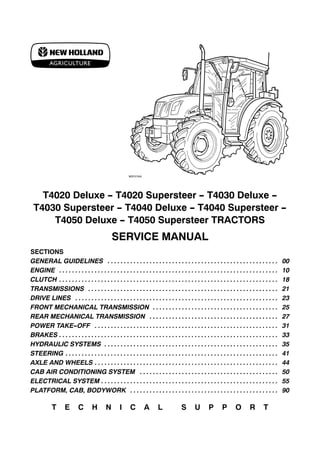
  • 1. T4020 Deluxe - T4020 Supersteer - T4030 Deluxe - T4030 Supersteer - T4040 Deluxe - T4040 Supersteer - T4050 Deluxe - T4050 Supersteer TRACTORS SERVICE MANUAL SECTIONS GENERAL GUIDELINES 00 . . . . . . . . . . . . . . . . . . . . . . . . . . . . . . . . . . . . . . . . . . . . . . . . . . . . . ENGINE 10 . . . . . . . . . . . . . . . . . . . . . . . . . . . . . . . . . . . . . . . . . . . . . . . . . . . . . . . . . . . . . . . . . . . . CLUTCH 18 . . . . . . . . . . . . . . . . . . . . . . . . . . . . . . . . . . . . . . . . . . . . . . . . . . . . . . . . . . . . . . . . . . . . TRANSMISSIONS 21 . . . . . . . . . . . . . . . . . . . . . . . . . . . . . . . . . . . . . . . . . . . . . . . . . . . . . . . . . . . DRIVE LINES 23 . . . . . . . . . . . . . . . . . . . . . . . . . . . . . . . . . . . . . . . . . . . . . . . . . . . . . . . . . . . . . . . FRONT MECHANICAL TRANSMISSION 25 . . . . . . . . . . . . . . . . . . . . . . . . . . . . . . . . . . . . . . . REAR MECHANICAL TRANSMISSION 27 . . . . . . . . . . . . . . . . . . . . . . . . . . . . . . . . . . . . . . . . POWER TAKE-OFF 31 . . . . . . . . . . . . . . . . . . . . . . . . . . . . . . . . . . . . . . . . . . . . . . . . . . . . . . . . . BRAKES 33 . . . . . . . . . . . . . . . . . . . . . . . . . . . . . . . . . . . . . . . . . . . . . . . . . . . . . . . . . . . . . . . . . . . . HYDRAULIC SYSTEMS 35 . . . . . . . . . . . . . . . . . . . . . . . . . . . . . . . . . . . . . . . . . . . . . . . . . . . . . . STEERING 41 . . . . . . . . . . . . . . . . . . . . . . . . . . . . . . . . . . . . . . . . . . . . . . . . . . . . . . . . . . . . . . . . . . AXLE AND WHEELS 44 . . . . . . . . . . . . . . . . . . . . . . . . . . . . . . . . . . . . . . . . . . . . . . . . . . . . . . . . . CAB AIR CONDITIONING SYSTEM 50 . . . . . . . . . . . . . . . . . . . . . . . . . . . . . . . . . . . . . . . . . . . ELECTRICAL SYSTEM 55 . . . . . . . . . . . . . . . . . . . . . . . . . . . . . . . . . . . . . . . . . . . . . . . . . . . . . . . PLATFORM, CAB, BODYWORK 90 . . . . . . . . . . . . . . . . . . . . . . . . . . . . . . . . . . . . . . . . . . . . . . T E C H N I C A L S U P P O R T
  • 2. INTRODUCTORY NOTES - This manual is divided into sections identified by two-figure numbers and each section has independent page numbering. - The different sections can easily be found by consulting the table of contents on the following pages. - The document number of the manual and the edition/update dates are given at the bottom of each page. - Pages updated in the future will be identified by the same document number followed by an additional digit: first edition standard manual 87666787A - 1st update 87666787A1 - 2nd update 87666787A2 - etc. The update pages can replace or supplement the pages of the standard manual; the information necessary for the procedure for adding or replacing pages is given on the title page of the update. The publication will be completed with an appropriate index. If it is necessary to issue a new updated manual (2nd edition) it will have document number 87666787B, this indicates that the manual is composed of the standard version 87666787A completed with all the updates: 1st update 87666787A1 - 2nd update 87666787A2 - etc. - The information contained in this manual was current on the date printed on each section. As NEWHOLLAND constantly improves its product range, some information may be out of date subsequent to modifications implemented for technical or commercial reasons, or to meet legal requirements in different countries. In the event of conflicting information, consult the NEW HOLLAND Sales and Service Departments. IMPORTANT WARNINGS - All maintenance and repair work described in this manual must be performed exclusively by NEW HOLLAND service technicians, in strict accordance with the instructions given and using any specific tools necessary. - Anyone performing the operations described herein without strictly following the instructions is personally responsible for any eventual injury or damage to property. - The Manufacturer and all organisations belonging to the Manufacturer's distribution network, including but not restricted to national, regional or local distributors, will accept no responsibility for personal injury or damage to property caused by abnormal function of parts and/or components not approved by the Manufacturer, including those used for maintenance and/or repair of the product manufactured or marketed by the Manufacturer. In any case, the product manufactured or marketed by the Manufacturer is covered by no guarantee of any kind against personal injury or damage to property caused by abnormal function of parts and/or components not approved by the Manufacturer. No part of the text or illustrations may be reproduced PRINTED IN FRANCE © CNH GLOBAL N.V. Print No. 87666787A1 - 03 - 2008
  • 3. CONTENT 3 87666787A2 − 06 − 2009 CONTENT Page Date 00 − GENERAL GUIDELINES General instructions . . . . . 1−2 11−07 Safety regulations . . . . . . . 3−4−5 11−07 Tractor refuelling . . . . . . . . 6 11−07 10 − ENGINE CHAPTER 1 − Engine T4040 and T4050 models Summary . . . . . . . . . . . . . . . 1 11−07 General specifications . . . . 2−3−4 11−07 Fuel system data . . . . . . . . 4 11−07 Engine block data . . . . . . . 5 11−07 Crankshaft data . . . . . . . . . 5 11−07 Connecting rod data . . . . . 6 11−07 Piston data . . . . . . . . . . . . . 6−7 11−07 Timing gear data . . . . . . . . 7 11−07 Cylinder head data . . . . . . 8−9 11−07 Tightening torques . . . . . . . 10−11 11−07 Tools . . . . . . . . . . . . . . . . . . 12 11−07 Engine diagrams . . . . . . . . 13 11−07 Lubrication diagrams . . . . . 14 11−07 Cooling diagram . . . . . . . . . 15 11−07 Additional counterweight diagrams . . . . . . . . . . . . . . . 16 11−07 Exhaust gas recirculation system (EGR) . . . . . . . . . . . 17 11−07 Fault finding . . . . . . . . . . . . 18−19−20− 21 11−07 Engine removal−installa- tion . . . . . . . . . . . . . . . . . . . . 22−23−24− 25−26−27− 28−29−30− 31−32 11−07 Page Date Engine disassembly− assembly . . . . . . . . . . . . . . . 33−34−35− 36−37−38− 39−40−41− 42−43−44− 45−46−47− 48−49−50− 51−52−53− 54−55−56− 57−58−59− 60−61−62− 63−64−65− 66 11−07 Checks and measurements − cylinder block and liners 67−68−69 11−07 Checks and measurements − crankshaft, bearings and flywheel . . . . . . 70−71 11−07 Checks and measurements − connecting rods . . . . . . . 72−73 11−07 Checks and measurements − pistons . . . . . 74−75−76− 77 11−07 Checks and measurements − camshaft, tappets and valves . . . . . . . . . . . . . . . . . 78−79−80− 81 11−07 Checks and measurements − cylinder head 82 11−07 Checks and measurements − lubrication system . . . . . . 83 11−07 Checks and measurements − cooling system . . . . . . . . 84 11−07 Removal−Installation − crankshaft front seal . . . . . 85−86 11−07 Replacing crankshaft rear seal . . . . . . . . . . . . . . . . . . . 87−88−89 11−07 Valve clearance adjustment . . . . . . . . . . . . . . 90−91 11−07 Removal−Installation − in- jectors . . . . . . . . . . . . . . . . . 92−93−94 11−07 Removal − Installation − Bosch injection pump . . . . 95−96−97 11−07 Bosch injection pump − tim- ing . . . . . . . . . . . . . . . . . . . . 98−99−100 11−07 Bosch injection pump − air bleeding . . . . . . . . . . . . . . . . 100 11−07
  • 4. 4 CONTENT 87666787A2 − 06 − 2009 Page Date Removal−Installation − coolant pump . . . . . . . . . . . 101−102 11−07 Removal−Installation − thermostat valve . . . . . . . . . 103−104 11−07 Removal−Installation − radiator . . . . . . . . . . . . . . . . 105−106− 107−108 11−07 Coolant pump and gener- ator drive belt . . . . . . . . . . . 109−110 11−07 CHAPTER 2 − Engine T4020 and T4030 models Summary . . . . . . . . . . . . . . . 1 03−08 General specifications . . . . 2−3 03−08 Engine removal−installa- tion . . . . . . . . . . . . . . . . . . . . 4−5−6−7−8 −9−10−11− 12−13−14− 15−16−17 03−08 18 − CLUTCH Data . . . . . . . . . . . . . . . . . . . 1−2 11−07 Tightening torques . . . . . . . 2 11−07 Tools . . . . . . . . . . . . . . . . . . 2−3 11−07 Sections . . . . . . . . . . . . . . . 3−4 11−07 Fault finding . . . . . . . . . . . . 5 11−07 Removal−Installation − clutch . . . . . . . . . . . . . . . . . . 6−7−8−9− 10−11−12− 13−14−15 11−07 Clutch Overhaul . . . . . . . . . 16−17−18− 19−20 11−07 Checks and measurements − clutch . . . . . . . . . . . . . . . . 21−22 11−07 Adjustments − clutch disen- gagement levers . . . . . . . . 22−23 11−07 Adjustments − clutch pedal 24 11−07 PTO control adjustment . . 25 11−07 Sectional view of PTO clutch servo control . . . . . . 26 11−07 Description and operation of PTO servo control . . . . . 27−28 11−07 PTO servo control adjust- ment . . . . . . . . . . . . . . . . . . . 29 11−07 PTO engaged switch ad- justment . . . . . . . . . . . . . . . . 30 11−07 Page Date 21 − TRANSMISSIONS CHAPTER 1 − Transmission and range gear (16x16) Data . . . . . . . . . . . . . . . . . . . 1−2 11−07 Tightening torques . . . . . . . 2−3 11−07 Tools . . . . . . . . . . . . . . . . . . 4−5−6−7 11−07 Sections . . . . . . . . . . . . . . . 8−9−10−11 11−07 Description and operation 12 11−07 Fault finding . . . . . . . . . . . . 12−13 11−07 Removal−Installation − rear transmission − gear- box casing . . . . . . . . . . . . . . 14−15−16− 17−18−19− 20 11−07 Disassembly−Assembly − transmission−gearbox cas- ing . . . . . . . . . . . . . . . . . . . . 21−22−23− 24−25−26− 27−28 11−07 Gearbox driving and driven shafts end float adjustment 29 11−07 Sealing compound applica- tion diagram . . . . . . . . . . . . 30 11−07 Gearbox control lever. Re- moval − Installation . . . . . . 31 11−07 Range gear control lever. Removal − Installation . . . . 32 11−07 Shuttle control lever. Re- moval − Installation . . . . . . 33 11−07 Fuel tank. Removal − In- stallation . . . . . . . . . . . . . . . 34−35 11−07 CHAPTER 2 − Mechanical transmission and splitter Data . . . . . . . . . . . . . . . . . . . 1−2 11−07 Tightening torques . . . . . . . 2 11−07 Tools . . . . . . . . . . . . . . . . . . 2 11−07 Sections . . . . . . . . . . . . . . . 3−4−5 11−07 Description and operation . 6 11−07 Fault finding . . . . . . . . . . . . 7 11−07 Splitter device and creeper unit casing, shafts and bearings disassembly . . . . 8−9−10 11−07
  • 5. CONTENT 5 87666787A2 − 06 − 2009 Page Date CHAPTER 3 − Power Shuttle transmission with dual command (2 Speed Power Shift) function Data . . . . . . . . . . . . . . . . . . . 1−2 11−07 Tightening torques . . . . . . . 3 11−07 Tools . . . . . . . . . . . . . . . . . . 4−5−6 11−07 Sections . . . . . . . . . . . . . . . 7−8−9−10− 11 11−07 Clutch control pressure test 10 11−07 Description and operation . 12 11−07 Fault finding . . . . . . . . . . . . 12 11−07 Disassembly−Assembly − transmission−gearbox cas- ing . . . . . . . . . . . . . . . . . . . . 13−14 11−07 Disassembly−Reassembly − Power Shuttle control valve . . . . . . . . . . . . . . . . . . 15−16−17 11−07 Disassembly−Assembly − accumulator . . . . . . . . . . . . 18 11−07 Gearbox control valve sole- noid valve. Removal − In- stallation . . . . . . . . . . . . . . . 19−20 11−07 Disassembly−Assembly − clutch casing . . . . . . . . . . . . 21−22−23− 24 11−07 CHAPTER 4 − Power Shuttle transmission (16 + 16 and 8 + 8 versions) Data . . . . . . . . . . . . . . . . . . . 1 11−07 Tightening torques . . . . . . . 2 11−07 Sections . . . . . . . . . . . . . . . 3−4−5−6 11−07 Clutch control pressure test 6 11−07 23 − DRIVE LINES Data . . . . . . . . . . . . . . . . . . . 1 11−07 Tightening torques . . . . . . . 2 11−07 Tools . . . . . . . . . . . . . . . . . . 3−4 11−07 Sections . . . . . . . . . . . . . . . 5−6−7 11−07 Description and operation . 8−9 11−07 Fault finding . . . . . . . . . . . . 9 11−07 Drive shafts and guard. Disassembly− Assembly . . 10−11−12 11−07 Removal−Installation − drive gear casing . . . . . . . . 13−14 11−07 Page Date Disassembly−Assembly − drive gear casing . . . . . . . . 15−16−17− 18 11−07 25 − FRONT AXLE MECHANICAL TRANSMISSION CHAPTER 1 − Front mechanical transmission (mod. T4040 Supersteer and T4050 Supersteer) Data . . . . . . . . . . . . . . . . . . . 1−2−3 11−07 Tightening torques . . . . . . . 4−5−6 11−07 Tools . . . . . . . . . . . . . . . . . . 7−8−9 11−07 Sections . . . . . . . . . . . . . . . 10−11−12− 13 11−07 Description and operation 13−14 11−07 Fault finding . . . . . . . . . . . . 15 11−07 Removal−Installation − front axle . . . . . . . . . . . . . . . 16−17−18− 19 11−07 Removal−Installation − front axle differential and bevel drive support . . . . . . 20−21−22− 23 11−07 Overhaul − front axle bevel drive . . . . . . . . . . . . . . . . . . . 24−25 11−07 Adjustments − bevel drive 26−27−28− 29−30−31 11−07 Overhaul − front differential 32 11−07 Overhaul − differential lock unit . . . . . . . . . . . . . . . . . . . . 33−34−35 11−07 Disassembly−Assembly − front epicyclic final drive with brake . . . . . . . . . . . . . . 36−37−38− 39 11−07 Disassembly−Assembly − front epicyclic final drive . . 40−41−42 11−07 Wheel hub seal. Renew . . 43 11−07 Wheel hub and steering knuckle. Disassembly− As- sembly . . . . . . . . . . . . . . . . . 44 11−07 Adjustments − steering knuckle bearings . . . . . . . . 45 11−07 Replacing steering knuckle pins and bearings . . . . . . . 46 11−07 Lead−drive wheel position check . . . . . . . . . . . . . . . . . . 47 11−07
  • 6. 6 CONTENT 87666787A2 − 06 − 2009 Page Date CHAPTER 2 − Front mechanical transmission (mod. T4040 Deluxe and T4050 Deluxe) Data . . . . . . . . . . . . . . . . . . . 1−2 11−07 Tightening torques . . . . . . . 3−4 11−07 Tools . . . . . . . . . . . . . . . . . . 5−6 11−07 Sections . . . . . . . . . . . . . . . 7−8 11−07 Description and operation 8−9 11−07 Fault finding . . . . . . . . . . . . 10 11−07 Removal−Installation − front axle . . . . . . . . . . . . . . . 11−12−13− 14 11−07 Front axle. Disassembly− Assembly . . . . . . . . . . . . . . 15−16−17− 18−19−20− 21−22−23 11−07 Overhaul − differential lock unit . . . . . . . . . . . . . . . . . . . . 24−25 11−07 Replacing steering knuckle pins and bearings . . . . . . . 26 11−07 Adjustments − steering knuckle bearings . . . . . . . . 27−28 11−07 Adjustments − bevel drive 29−30−31− 32−33−34− 35 11−07 Overhaul − front differential 36 11−07 LIM−SLIP self−locking dif- ferential . . . . . . . . . . . . . . . . 37−38 11−07 Checking leading wheel alignment . . . . . . . . . . . . . . 39 11−07 Disassembly−Assembly − front epicyclic final drive . . 40−41 11−07 Disassembly−Assembly − front epicyclic final drive with brake . . . . . . . . . . . . . . 42−43−44 11−07 27 − REAR MECHANICAL TRANSMISSION Data . . . . . . . . . . . . . . . . . . . 1−2 11−07 Tightening torques . . . . . . . 3−4 11−07 Tools . . . . . . . . . . . . . . . . . . 5−6−7−8 11−07 Sections . . . . . . . . . . . . . . . 9−10 11−07 Description and operation . 11−12 11−07 Fault finding . . . . . . . . . . . . 12−13 11−07 Disassembly−Assembly − transmission−gearbox cas- ing . . . . . . . . . . . . . . . . . . . . 14−15−16− 17−18−19 11−07 Page Date Adjustments − differential lock engagement sleeve position . . . . . . . . . . . . . . . . 20 11−07 Adjustments − bevel drive 21−22−23− 24−25 11−07 Removal−Installation − final drive casing . . . . . . . . 26−27−28− 29 11−07 Disassembly−Assembly − drive wheel shaft . . . . . . . . 29−30−31 11−07 Disassembly−Assembly − epicyclic final drive . . . . . . . 31 11−07 31 − POWER TAKE−OFF CHAPTER 1 − Mechanical power take−off Data . . . . . . . . . . . . . . . . . . . 1−2−3 11−07 Tools . . . . . . . . . . . . . . . . . . 4 11−07 Tightening torques . . . . . . . 5−6 11−07 Sections . . . . . . . . . . . . . . . 7−8 11−07 Description and operation . 9−10−11 11−07 Fault finding . . . . . . . . . . . . 11 11−07 Disassembly − Assembly − power take−off . . . . . . . . . . 12−13−14− 15 11−07 33 − BRAKES Data . . . . . . . . . . . . . . . . . . . 1−2 11−07 Tightening torques . . . . . . . 2 11−07 Sections . . . . . . . . . . . . . . . 3−4−5 11−07 Tools . . . . . . . . . . . . . . . . . . 5−6 11−07 Description and operation . 6 11−07 Fault finding . . . . . . . . . . . . 7−8 11−07 Removal−Installation − ser- vice brake . . . . . . . . . . . . . . 9−10 11−07 Removal−Installation − ser- vice brake pump . . . . . . . . . 11−12−13− 14 11−07 Adjustments − service brake pedals travel . . . . . . 15−16 11−07 Service brake circuit air bleeding . . . . . . . . . . . . . . . . 16−17−18 11−07 Removal−Installation − parking brake . . . . . . . . . . . 19−20 11−07
  • 7. CONTENT 7 87666787A2 − 06 − 2009 Page Date Adjustments − parking handbrake travel . . . . . . . . 21 11−07 35 − HYDRAULIC SYSTEMS CHAPTER 1 − Rear mechanical hydraulic lift Data . . . . . . . . . . . . . . . . . . . 1−2−3 11−07 Tightening torques . . . . . . . 3−4 11−07 Tools . . . . . . . . . . . . . . . . . . 5−6 11−07 Sections . . . . . . . . . . . . . . . 7−8−9−10− 11 11−07 Description and operation . 12−13−14− 15 11−07 Fault finding . . . . . . . . . . . . 16−17 11−07 Lift internal controls. Disas- sembly− Assembly . . . . . . . 18−19−20− 21 11−07 Adjusting the lift . . . . . . . . . 22−23−24− 25−26−27− 28−29−30− 31 11−07 Lift cylinder and arms shaft. Disassembly− Assembly . . 32−33−34− 35 11−07 Disassembly−Assembly − lift control valve . . . . . . . . . 36−37−38− 39 11−07 Lift pressure relief valve . . 40 11−07 CHAPTER 2 − Open centre system auxiliary control valves Data . . . . . . . . . . . . . . . . . . . 2 11−07 Tools . . . . . . . . . . . . . . . . . . 2 11−07 Tightening torques . . . . . . . 2 11−07 Sections . . . . . . . . . . . . . . . 3−4 11−07 Description and operation . 5−6−7−8 11−07 Lift electronic control unit. Renew . . . . . . . . . . . . . . . . . 9 11−07 Auxiliary control valves. Disassembly− Assembly . . 10−11−12 11−07 CHAPTER 3 − Trailer brakes auxiliary control valves Sections . . . . . . . . . . . . . . . 1 11−07 Description and operation . 1−2−3−4−5 −6−7 11−07 Fault finding . . . . . . . . . . . . 8−9−10 11−07 Page Date Removal−Installation − trailer brake valve . . . . . . . 11 11−07 CHAPTER 4 − Electronically controlled hydraulic lift Data . . . . . . . . . . . . . . . . . . . 2−3 11−07 Tightening torques . . . . . . . 4 11−07 Tools . . . . . . . . . . . . . . . . . . 4−5−6 11−07 Sections . . . . . . . . . . . . . . . 7−8−9 11−07 Location of Components . . 10−11−12 11−07 Description and operation . 13−14−15− 16−17−18 11−07 Removal−Installation − lift . 19−20−21− 22−23 11−07 Draft sensor support. Re- moval − Installation . . . . . . 24 11−07 Replacement − control unit 25 11−07 Lift arm potentiometer. Renew . . . . . . . . . . . . . . . . . 26−27 11−07 Replacement − draft sensor . . . . . . . . . . . . . . 28−29 11−07 Electronically controlled hy- draulic lift. Disassembly− Assembly . . . . . . . . . . . . . . 30−31−32− 33−34 11−07 Removal−Installation − hy- draulic control valve . . . . . . 35 11−07 Hydraulic control valve. Disassembly− Assembly . . 36−37−38 11−07 CHAPTER 5 − Constant flow gear pump Data . . . . . . . . . . . . . . . . . . . 1−2 11−07 Description and operation . 2 11−07 Diagrams . . . . . . . . . . . . . . . 3 11−07 Disassembly−Assembly − lift oil pump . . . . . . . . . . . . . 4 11−07 CHAPTER 6 − Electronic lift and front Power Take−Off Main specifications of front lift . . . . . . . . . . . . . . . . . . . . . 1−2−3 11−07 Tightening torques . . . . . . . 3−4−5 11−07 Cross−sectional views of implement linkage . . . . . . . 6−7 11−07 Cross−sectional views of front PTO . . . . . . . . . . . . . . 8−9−10 11−07
  • 8. 8 CONTENT 87666787A2 − 06 − 2009 Page Date Description and operation . 11−12−13− 14 11−07 Front lift hydraulic diagram 15 11−07 Front lift troubleshooting . . 16−17 11−07 Removal−Installation − Front power take−off trans- mission shaft . . . . . . . . . . . 18−19−20− 21−22−23− 24−25 11−07 Disassembly−Assembly − Front PTO transmission shaft . . . . . . . . . . . . . . . . . . . 26 11−07 Front PTO casing cross− sectional view . . . . . . . . . . . 27 11−07 Removal−Installation − Front PTO electromagnetic coupling . . . . . . . . . . . . . . . . 28−29−30 11−07 Disassembly−Assembly − Front PTO electromagnetic coupling . . . . . . . . . . . . . . . . 31−32−33− 34 11−07 Removal−Installation − Front lift support . . . . . . . . . 35−36−37 11−07 CHAPTER 7 − Front lift and power take−off (for mod. T4030 Deluxe, T4040 Deluxe and T4050 Deluxe) Data . . . . . . . . . . . . . . . . . . . 1−2 03−08 Tightening torques . . . . . . . 3−4 03−08 Sections . . . . . . . . . . . . . . . 5−6 03−08 Description and operation of front power take−off . . . 7 03−08 Front power take−off con- trol adjustment . . . . . . . . . . 8 03−08 Front power take−off con- trol valve . . . . . . . . . . . . . . . 9 03−08 Sectional view of front power take−off clutch . . . . 10 03−08 Front mechanical lift . . . . . 11 03−08 Electronic front lift . . . . . . . 12−13−14 03−08 Front electronic lift hy- draulic control valve dia- gram . . . . . . . . . . . . . . . . . . . 15 03−08 Front electronic lift hy- draulic control valve . . . . . . 16 03−08 Page Date Description and operation of front electronic lift hy- draulic control valve . . . . . . 17−18−19− 20 03−08 Fault finding . . . . . . . . . . . . 21−22 03−08 Front electronic lift operat- ing instructions . . . . . . . . . . 23−24−25− 26 03−08 Front electronic lift calibra- tion . . . . . . . . . . . . . . . . . . . . 27−28−29 03−08 Removal−Installation − front mechanical/electronic lift . . . . . . . . . . . . . . . . . . . . . 30−31 03−08 Removal−Installation − front power take−off . . . . . . 32−33 03−08 Disassembly−Assembly − front power take−off . . . . . . 34−35 03−08 Removal−Installation − front electronic lift control unit . . . . . . . . . . . . . . . . . . . . 36 03−08 Removal−Installation − front electronic lift hydraulic control valve . . . . . . . . . . . . 37 03−08 Fault code indication . . . . . 38 03−08 Diagnostics . . . . . . . . . . . . . 39−40−41− 42−43−44− 45−46−47− 48−49−50− 51−52−53− 54−55−56 06−09 41 − STEERING CHAPTER 1 − Steering Data . . . . . . . . . . . . . . . . . . . 2 11−07 Tightening torques . . . . . . . 2 11−07 Tools . . . . . . . . . . . . . . . . . . 2 11−07 Description and operation . 3−4−5 11−07 View of hydrostatic steering control valve components . 6 11−07 Fault finding . . . . . . . . . . . . 7−8 11−07 Replacement − hydrostatic steering wheel . . . . . . . . . . 9 11−07 Removal−Installation − hy- drostatic steering control valve . . . . . . . . . . . . . . . . . . 10−11−12 11−07
  • 9. CONTENT 9 87666787A2 − 06 − 2009 Page Date Disassembly−Assembly − hydrostatic control valve . . 13−14−15− 16−17−18− 19−20−21− 22−23−24− 25−26−27− 28 11−07 Hydrostatic steering control valve bench testing . . . . . . 29−30 11−07 Pressure relief valve testing 31 11−07 Steering control cylinder. Removal − Installation . . . . 32−33 11−07 Steering control cylinder. Disassembly−Assembly . . 34−35 11−07 CHAPTER 2 − Constant flow gear pump Data . . . . . . . . . . . . . . . . . . . 1−2 11−07 Diagrams . . . . . . . . . . . . . . . 3−4 11−07 Description and operation . 4 11−07 Disassembly−Assembly − hydrostatic steering oil pump . . . . . . . . . . . . . . . . . . 5 11−07 44 − AXLES AND WHEELS Data . . . . . . . . . . . . . . . . . . . 1−2 11−07 Front wheel track diagram 2 11−07 Sections . . . . . . . . . . . . . . . 3 11−07 Tightening torques . . . . . . . 4−5−6 11−07 Tools . . . . . . . . . . . . . . . . . . 6−7 11−07 Fault finding . . . . . . . . . . . . 7 11−07 Disassembly−Assembly − wheel axle hub . . . . . . . . . . 8−9−10 11−07 Removal−Installation − front axle . . . . . . . . . . . . . . . 11−12−13 11−07 Stub axle hub overhaul . . . 14−15−16− 17 11−07 Checking leading wheel alignment . . . . . . . . . . . . . . 18 11−07 50 − CAB AIR CONDITIONING SYSTEM Safety regulations . . . . . . . 2 11−07 Data . . . . . . . . . . . . . . . . . . . 3 11−07 Tools . . . . . . . . . . . . . . . . . . 4 11−07 Operating principles . . . . . 5 11−07 Page Date Conditioning system com- ponents . . . . . . . . . . . . . . . . 6−7−8−9− 10 11−07 Cab controls . . . . . . . . . . . . 11−12−13 11−07 Testing operation and cool- ing . . . . . . . . . . . . . . . . . . . . 14−15 11−07 Air conditioning system maintenance . . . . . . . . . . . . 16−17 11−07 Fault finding . . . . . . . . . . . . 18−19−20− 21 11−07 Refrigerant recovery − re- cycling and evacuation − charging stations . . . . . . . . 22−23 11−07 Dehydration, recharging and refrigeration check . . . 24−25−26− 27−28−29− 30 11−07 Checking for and eliminat- ing any gas leaks . . . . . . . . 31−32 11−07 Compressor drive belt ten- sion adjustment . . . . . . . . . 33 11−07 Cab air infeed vents. Re- moval − Installation . . . . . . 34 11−07 Cab heating/air−condition- ing system. Removal − In- stallation . . . . . . . . . . . . . . . 35−36 11−07 Cab heater. Disassembly− Assembly . . . . . . . . . . . . . . 37 11−07 Cab air conditioning system evaporator unit. Disassem- bly− Assembly . . . . . . . . . . 38 11−07 Cab electric fan unit. Disas- sembly− Assembly . . . . . . . 39 11−07 55 − ELECTRICAL SYSTEM CHAPTER 1 − Instruments Analogue instrumentation . 1−2−3−4 11−07 Digital instrumentation . . . . 5−6−7−8−9 11−07 Transmitters, sensors and switches . . . . . . . . . . . . . . . 10−11−12− 13−14−15− 16−17 11−07 CHAPTER 2 − Components Introduction . . . . . . . . . . . . . 1 11−07
  • 10. 10 CONTENT 87666787A2 − 06 − 2009 Page Date Components . . . . . . . . . . . . 1−2−3−4−5 −6−7 11−07 Service . . . . . . . . . . . . . . . . 8−9−10−11 −12 11−07 CHAPTER 3 − Starting System Technical data . . . . . . . . . . 1 11−07 Description and operation . 2 11−07 Fault finding . . . . . . . . . . . . 3 11−07 System testing . . . . . . . . . . 4−5−6 11−07 View of starter motor com- ponents . . . . . . . . . . . . . . . . 7 11−07 Revision . . . . . . . . . . . . . . . 8−9 11−07 Starter motor testing . . . . . 9−10 11−07 CHAPTER 4 − Charging system Technical data . . . . . . . . . . 1 11−07 Tightening torques . . . . . . . 1 11−07 Description and operation . 2−3 11−07 System testing . . . . . . . . . . 4−5−6−7−8 −9 11−07 Removal−Installation and Overhaul − alternator . . . . 9−10−11− 12−13−14− 15−16 11−07 CHAPTER 5 − Battery Technical data . . . . . . . . . . 1 11−07 Description and operation . 1 11−07 Removal−Installation− bat- tery . . . . . . . . . . . . . . . . . . . . 2 11−07 Battery Service . . . . . . . . . . 3 11−07 Battery charging . . . . . . . . . 4−5−6 11−07 Battery troubleshooting . . . 6 11−07 CHAPTER 6 − Electrical circuits for tractors with cab Index . . . . . . . . . . . . . . . . . . 1 06−09 CHAPTER 7 − Electrical circuits for tractors with platform Index . . . . . . . . . . . . . . . . . . 1 11−07 CHAPTER 8 − Connectors Index . . . . . . . . . . . . . . . . . . 1 11−07 CHAPTER 9 − Error codes Index . . . . . . . . . . . . . . . . . . 1 06−09 Page Date CHAPTER 10 − HH Menu and calibrations Index . . . . . . . . . . . . . . . . . . 1 06−09 CHAPTER 11 − Front electronic lift (mod. T4030 Deluxe, T4040 Deluxe and T4050 Deluxe) Index . . . . . . . . . . . . . . . . . . 1 03−08 Electrical circuit compo- nents . . . . . . . . . . . . . . . . . . 2−3 03−08 Wiring diagrams . . . . . . . . 4 03−08 Wiring diagrams . . . . . . . . . 6−7−8−9− 10−11 03−08 Connectors . . . . . . . . . . . . . 14−15−16− 17−18−19− 20 03−08 90 − PLATFORM, CAB, BODYWORK CHAPTER 1 − Cab Hood. Removal − Installa- tion . . . . . . . . . . . . . . . . . . . . 2 11−07 Instrument panel lower guard. Removal − Installation . . . . 3 11−07 Platform assembly. Removal − Installation . . . . 4−5−6−7− 8−9−10 11−07 Canopy for rops. Removal − Installation . . . . . . . . . . . . 11 11−07 Cab assembly with plat- form. Removal − Installation . . . . 12−13−14− 15−16−17− 18−19 11−07 Cab windows. Renew . . . . 20−21−22 11−07 Right/left−hand upright seals. Removal − Installation . . . . 23 11−07 Cab ceiling fitting. Removal − Installation . . . . 24−25 11−07 Sunshade. Removal − Installation . . . . 26 11−07
  • 11. SECTION 00 - - GENERAL - - CHAPTER 1 1 87666787A - - 11 - - 2007 GENERAL INSTRUCTIONS IMPORTANT NOTICE All maintenance and repair work described in this manual must be performed exclusively by NEW HOLLAND service technicians, in strict accordance with the instructions given and using any specific tools necessary. Anyone performing the operations described herein without strictly following the instructions is personally responsible for any eventual injury or damage to property. BATTERY Before carrying out any kind of service operation disconnect and isolate the battery negative lead, unless otherwise requested for specific operations (e.g.: operations that require the engine running). Once the specific operation has been completed, disconnect the lead in order to complete the operation. SHIMMING For each adjustment operation, select adjusting shims and measure individually using a micrometer, then add up the recorder values: Do not rely on measuring the entire shimming set, which may be incorrect, or the rated value indicated for each on shim. ROTATING SHAFT SEALS For correct rotating shaft seal installation, proceed as follows: -- before assembly, allow the seal to soak in the oil it will be sealing for at least thirty minutes; -- thoroughly clean the shaft and check that the working surface on the shaft is not damaged; -- position the sealing lip facing the fluid; with hydrodynamic lips, take into consideration the shaft rotation direction and position the grooves so that they will deviate the fluid towards the inner side of the seal; -- smear the sealing lip with a thin layer of lubricant (use oil rather than grease) and fill the gap between the sealing lip and the dust lip on double lip seals with grease; -- insert the seal in its seat and press down using a flat punch; do not tap the seal with a hammer or mallet; -- whilst inserting the seal, check that the it is perpendicular to the seat; once settled, make sure that it makes contact with the thrust element, if required; -- to prevent damaging the seal lip on the shaft, position a protective guard during installation operations. O- -RING SEALS Lubricate the O--RING seals before inserting them in the seats, this will prevent them from overturning and twisting, which would jeopardise sealing efficiency. SEALING COMPOUNDS Apply one of the following sealing compounds on the mating surfaces marked with an X: RTV SILMATE, RHODORSIL CAF 1 or LOCTITE PLASTIC GASKET. Before applying the sealing compound, prepare the surfaces as follows: -- remove any incrustations using a wire brush; -- thoroughly de--grease the surfaces using one of the following cleaning agents: trichlorethylene, petrol or a water and soda solution. BEARINGS When installing bearings it is advised to: -- heat the bearings to 80 ÷ 90 0C before fitting on the shafts; -- allow the bearings to cool before installing them from the outside.
  • 12. 2 SECTION 00 - - GENERAL - - CHAPTER 1 87666787A - - 11 - - 2007 SPRING PINS When fitting split socket elastic pins, ensure that the pin notch is positioned in the direction of the force required to stress the pin. Spiral spring pins do not require special positioning SPARE PARTS Use genuine parts only. Only genuine spare parts guarantee the same quality, duration and safety as they are the same parts that are assembled during production. Only genuine parts can offer this guarantee. When ordering spare parts, always provide the following information: -- tractor model (commercial name) and frame number; -- engine type and number; -- part number of the ordered part, which can be found in the ”Microfiches” or the ”Spare Parts Catalogue”, used for order processing. NOTES FOR EQUIPMENT The tools that NEW HOLLAND propose and illustrate in this manual are: -- specifically researched and designed for use with NEW HOLLAND vehicles; -- necessary to make reliable repair; -- accurately built and strictly tested to offer efficient and long--lasting working means. By using these tools, repair personnel will benefit from: -- operating in optimal technical conditions; -- obtaining the best results; -- saving time and effort; -- working in safe conditions. IMPORTANT NOTES Wear limit values indicated for certain parts are recommended, but not binding. The terms ”front”, ”rear”, ”right--hand” and ”left--hand” (when referred to different parts) are intended as seen from the driving position with the tractor in the normal direction of movement. MOVING THE TRACTOR WITH THE BATTERY REMOVED External power supply cables should only be connected to the respective positive and negative cable terminals, using efficient clamps that guarantee adequate and secure contact. Disconnect all services (lights, windshield wipers, etc.) before starting the vehicle. If the vehicle electrical system requires checking, carry out operations with the power supply connected; once checking is completed, disconnect all services and switch off the power supply before disconnecting the cables.
  • 13. SECTION 00 - - GENERAL - - CHAPTER 1 3 87666787A - - 11 - - 2007 SAFETY REGULATIONS WARNING AND DANGER SYMBOL This warning symbol points out important messages concerning your safety. Carefully read the following safety regulations and observe advised precautions in order to avoid potential hazards and safeguard your health and safety. In this manual the symbol is accompanied by the following key- -words: WARNING - - Warnings concerning unsuitable repair operations that may jeopardise the safety of Repair personnel. DANGER - - Specific warnings concerning potential hazards for operator safety or for other persons directly or indirectly involved. TO PREVENT ACCIDENTS Most accidents or injuries that occur in workshops are the result of non--observance of simple and fundamental safety regulations. For this reason, IN MOST CASES THESE ACCIDENTS CAN BE AVOIDED: by foreseeing possible causes and consequently acting with the necessary caution and care. Accidents may occur with all types of vehicle, regardless of how well it was designed and built. A careful and judicious service technician is the best guarantee against accidents. Precise observance of the most basic safety rule is normally sufficient to avoid many serious accidents. DANGER. Never carry out any cleaning, lubrication or maintenance operations when the engine is running. SAFETY REGULATIONS GENERAL -- Carefully follow specified repair and maintenance procedures. -- Do not wear rings, wristwatches, jewellery, unbuttoned or loose articles of clothing such as: ties, torn clothing, scarves, open jackets or shirts with open zips that may remain entangled in moving parts. It is advised to wear approved safety clothing, e.g.: non--slip footwear, gloves, safety goggles, helmets, etc. 1 -- Do not carry out repair operations with someone sitting in the driver’s seat, unless the person is a trained technician who is assisting with the operation in question. -- Do not operate the vehicle or use any of the implements from different positions, other than the driver’s seat. -- Do not carry out operations on the vehicle with the engine running, unless specifically indicated. -- Stop the engine and ensure that all pressure is relieved from hydraulic circuits before removing caps, covers, valves, etc. -- All repair and maintenance operations must be carried out using extreme care and attention. -- Service steps and platforms used in a workshop or in the field should be built in compliance with the safety rules in force. -- Disconnect the batteries and label all controls to indicate that the vehicle is being serviced. Block the machine and all equipment which should be raised. -- Do not check or fill fuel tanks, accumulator batteries, nor use starting liquid when smoking or near naked flames, as these fluids are inflammable. -- Brakes are inoperative when manually released for repair or maintenance purposes: Use blocks or similar devices to control the machine in these conditions. -- The fuel nozzle should always be in contact with the filling aperture: Maintain this contact until the fuel stops flowing into the tank to avoid possible sparks due to static electricity build--up.
  • 14. SECTION 10 - - ENGINE - - CHAPTER 1 1 87666787A - - 11 - - 2007 SECTION 10 - - ENGINE Chapter 1 - - Engine CONTENT Section Description Page 10 000 General specifications 2 . . . . . . . . . . . . . . . . . . . . . . . . . . . . . . . . . . . . . . . . . . . . . . . . . . . . . . . . . Specifications 4 . . . . . . . . . . . . . . . . . . . . . . . . . . . . . . . . . . . . . . . . . . . . . . . . . . . . . . . . . . . . . . . . Torque settings 10 . . . . . . . . . . . . . . . . . . . . . . . . . . . . . . . . . . . . . . . . . . . . . . . . . . . . . . . . . . . . . . Tools 12 . . . . . . . . . . . . . . . . . . . . . . . . . . . . . . . . . . . . . . . . . . . . . . . . . . . . . . . . . . . . . . . . . . . . . . . Cross--sectional views 13 . . . . . . . . . . . . . . . . . . . . . . . . . . . . . . . . . . . . . . . . . . . . . . . . . . . . . . . . Schematic diagrams 14 . . . . . . . . . . . . . . . . . . . . . . . . . . . . . . . . . . . . . . . . . . . . . . . . . . . . . . . . . . Troubleshooting 17 . . . . . . . . . . . . . . . . . . . . . . . . . . . . . . . . . . . . . . . . . . . . . . . . . . . . . . . . . . . . . . 10 001 10 Engine Removal--Installation 22 . . . . . . . . . . . . . . . . . . . . . . . . . . . . . . . . . . . . . . . . . . . . . . . . . . . 10 001 54 Engine Disassembly -- Assembly 33 . . . . . . . . . . . . . . . . . . . . . . . . . . . . . . . . . . . . . . . . . . . . . . . 10 102 70 Crankshaft front seal -- Replacement 85 . . . . . . . . . . . . . . . . . . . . . . . . . . . . . . . . . . . . . . . . . . . 10 102 74 Crankshaft rear seal -- Replacement 87 . . . . . . . . . . . . . . . . . . . . . . . . . . . . . . . . . . . . . . . . . . . . 10 106 12 Valve/rocker arm clearance 90 . . . . . . . . . . . . . . . . . . . . . . . . . . . . . . . . . . . . . . . . . . . . . . . . . . . . 10 218 30 Engine injectors Removal--Installation 92 . . . . . . . . . . . . . . . . . . . . . . . . . . . . . . . . . . . . . . . . . . . 10 246 14 Bosch injection pump Removal--Installation, timing and air bleeding 95 . . . . . . . . . . . . . . . . . 10 402 10 Coolant pump Removal--Installation 101 . . . . . . . . . . . . . . . . . . . . . . . . . . . . . . . . . . . . . . . . . . . 10 402 30 Thermostatic valve Removal/Installation 103 . . . . . . . . . . . . . . . . . . . . . . . . . . . . . . . . . . . . . . . . 10 406 10 Radiator Removal--Installation 105 . . . . . . . . . . . . . . . . . . . . . . . . . . . . . . . . . . . . . . . . . . . . . . . . 10 414 10 Coolant pump and generator drive belts Adjusting tension 109 . . . . . . . . . . . . . . . . . . . . . . . .
  • 15. 2 SECTION 10 - - ENGINE - - CHAPTER 1 87666787A - - 11 - - 2007 GENERAL SPECIFICATIONS Engine, technical type: -- Model T4040 type F4CE9484N*J601 (BOSCH pump) . . . . -- Model T4050 -- type F4CE9484M*J601 (BOSCH pump) . . Cycle . . . . . . . . . . . . . . . . . . . . . . . . . . . . . . . . . . . . . . . . . . . . . . . . . diesel, 4--stroke Fuel injection . . . . . . . . . . . . . . . . . . . . . . . . . . . . . . . . . . . . . . . . . . Direct Number of cylinders in line . . . . . . . . . . . . . . . . . . . . . . . . . . . . . . . 4 Piston diameter . . . . . . . . . . . . . . . . . . . . . . . . . . . . . . . . . . . . . . . . 104 mm Piston stroke . . . . . . . . . . . . . . . . . . . . . . . . . . . . . . . . . . . . . . . . . . 132 mm Total displacement . . . . . . . . . . . . . . . . . . . . . . . . . . . . . . . . . . . . . . 4485 cm3 Compression ratio . . . . . . . . . . . . . . . . . . . . . . . . . . . . . . . . . . . . . . 16.5:1 Maximum Power Output: -- Model T4040 -- type F4CE9484N*J601 . . . . . . . . . . . . . . . . . 63 kW (86 Hp) -- Model T4050 -- type F4CE0454C*D600/*D603 . . . . . . . . . . 71 kW (97 Hp) Maximum power speed . . . . . . . . . . . . . . . . . . . . . . . . . . . . . . . . . 2300 rpm -- Maximum torque: Model T4040 -- type F4CE9484N*J601 . 370 Nm -- Maximum torque: Model T4050 -- type F4CE9484M*J601 418 Nm Maximum torque speed . . . . . . . . . . . . . . . . . . . . . . . . . . . . . . . . . 1300 rpm Number of main bearings . . . . . . . . . . . . . . . . . . . . . . . . . . . . . . . . 5 Sump pan . . . . . . . . . . . . . . . . . . . . . . . . . . . . . . . . . . . . . . . . . . . . . structural, cast iron Lube . . . . . . . . . . . . . . . . . . . . . . . . . . . . . . . . . . . . . . . . . . . . . . . . . forced, with lobe pump Pump drive . . . . . . . . . . . . . . . . . . . . . . . . . . . . . . . . . . . . . . . . . . . . from crankshaft Engine speed/oil pump speed ratio . . . . . . . . . . . . . . . . . . . . . . . 1:1 Oil filtration . . . . . . . . . . . . . . . . . . . . . . . . . . . . . . . . . . . . . . . . . . . . mesh screen on oil pick--up and filter cartridge in delivery line Normal oil pressure with motor warmed--up at slow idling . . . . . . . . . . . . . . . . . . . . . . . . . . . . . . . . . . . . . . . . . . . 1.2 bar at fast idling . . . . . . . . . . . . . . . . . . . . . . . . . . . . . . . . . . . . . . . . . . . 3.9 bar (continued)
  • 16. 22 SECTION 10 - - ENGINE - - CHAPTER 1 87666787A - - 11 - - 2007 Op. 10 001 10 ENGINE Removal- -Installation DANGER Lift and handle all heavy parts using suitable lifting equipment. Make sure that assemblies or parts are supported by means of suitable slings and hooks. Ensure that no--one is in the vicinity of the load to be lifted. ATTENTION Use suitable tools to align the holes. NEVER USE FINGERS OR HANDS. 1. Remove the bonnet as described in operation 90 100 22. 2. Extract the fixing pin and remove the ballast (1); unscrew the retaining screws and retrieve the ballast support (2). 6 3. If the tractor is a T4040 Supersteer or T4050 Supersteer model, position and secure the bracket 380001613 (1) together with the spacers 50162 (4) on the front axle (3) and associated support (2). 7 4. Unscrew the retaining bolts and remove the side grille (1). Perform this operation on the other side of the tractor too. 8
  • 17. Suggest: If the above button click is invalid. Please download this document first, and then click the above link to download the complete manual. Thank you so much for reading
  • 18. SECTION 10 - - ENGINE - - CHAPTER 1 23 87666787A - - 11 - - 2007 5. Unscrew the related retaining bolt and loosen the guide (1), unhook the catch and take out the condenser (2). 9 6. Disconnect the electrical connection from the compressor (1) and unscrew the related retaining bolts. Remove the brackets fixing the pipes of the air conditioning system and take the condenser, compressor and pipes under the transmission without disconnecting the pipes. 10 7. Unscrew the bolts (3) securing the exhaust pipe (1), unscrew the exhaust silencer retaining bolts (2) and remove the entire assembly. Unscrew the retaining bolts and remove the heat shield. 11 8. Remove the guard (1) and disconnect the cables from the starter motor (2). 12