
Recommended
Recommended
More Related Content
What's hot
What's hot (9)
More from ufjjdjkskemem
More from ufjjdjkskemem (20)
Recently uploaded
Recently uploaded (20)
Clark wp 40 service repair manual
- 2. FOREWORD This service publication provides information covering normal service, maintenance and repair of the Clark industrial trucks noted on the cover. It has been specifically prepared to help owners and service personnel maintain these trucks in efficient and safe operating condition. Regular, correct maintenance and care of industrial trucks is not only important for long and efficient truck life; it is essential for safe operation. The importance of proper maintenance through planned service, inspection and qualified repairs cannot be emphasized too strongly. To assist in keeping industrial trucks in good operating condition, this manual includes preventive maintenance procedures to be performed at regular intervals. These are essential to the service life and safe operation of all industrial trucks. Instructions for safety inspections, operational checks, cleaning, and lubrication are provided for reference in setting-up and conducting a recommended periodic Planned Maintenance (PM) program. Refer to the Operator’s Manual, located on the truck, for additional information on the operation, care and maintenance of your truck. Genuine Clark replacement parts should be used for all service and repair requirements. Substitute parts from othersources may be different than original parts and may not meet OSHA or other safety requirements. Any reference to brand names other than Clark in this manual is made simply as an example of the type of tools and materials recommended for use and, as such, should not be considered as an endorsement. Equivalents, if available, may be used. For more information on maintenance and repair of these trucks, contact your authorized Clark dealer. NOTICE The descriptions and specifications included in this manual were in effect at the time of printing. Clark Equipment Company reserves the right to discontinue modelsatany time, or make improvements and changes in specifications or design without notice and without incurring obligation. Spectjications, torques, pressures, measurements, adjustments, illustrations and other items may change at any time. Contact your authorized CLARK dealer for information on possible updates or revisions. 0 1996 Clark Material Handling Company SM611 Aug 96
- 3. Safety Notice IMPORTANT SAFETY NOTICE Read and understand all safety precautions and warnings before performing repairs on lift trucks. Appropriate service methods and proper repair procedures are essential to the safe, reliable operation of industrial trucks as well as the personal safety of the individual doing the work. This Service Manual provides general directions for accomplishing service and repair work with tested, effective techniques. Following them will help assure successful repair and reliable truck operation. There are numerous variations in procedures, techniques, tools, and parts for servicing industrial trucks, as well as in the skill of the individual doing the work. This manual cannot possibly anticipate all such variations and provide advice or precautions as to each. Accordingly, anyone departing from the instructions provided in this manual through procedures used or choice of tools, materials, and parts may jeopardize his or her personal safety and/or the safety of the vehicle user. Improper or careless techniques cause accidents. Don’t take chances with incorrect or damaged equipment. Read and understand the procedures for safe operation and maintenance outlined in this manual. STAY ALERT! Follow safety rules, regulations and procedures. Accidents can be avoided by recognizing dangerous procedures or situations before they occur. DRIVE AND WORK SAFELY and follow the safety signs and their messages displayed on the truck and in this manual. General Precautions The following list contains general precautions that should be followed when working on a lift truck: Always wear safety glasses for eye protection. Remove rings, watches, loose jewelry and open clothing before working on a vehicle, to avoid serious injury. Do not smoke while working on a vehicle. Put ignition switch in the OFF position, unless otherwise required by the procedure. Set the parking brake. Place wheel chocks or wood blocks of 4” x 4” size or larger to the front and rear surfaces of the tires to provide further restraint from inadvertent vehicle movement. Use safety stands or blocks whenever a procedure requires you to be under the vehicle. Service Electric Truck Batteries in a well-ventilated area to avoid the danger of igniting explosive gases. Always Discharge the Capacitors prior to working on or around electrical components. Avoid contact with Battery Acid. The battery contains corrosive acid which can cause injury. SM611 Aug 96
- 4. TABLE OF CONTENTS Section 0 Maintenance 0.1 Truck Identification 0.2 System Operation 0.3 Specifications 0.4 Maintenance and Adjustments 0.5 Troubleshooting 0.6 Component Removal and Installation 0.7 Component Repair Section 1 Transmission 1.1 Component Identification 1.2 System Operation 1.3 Specifications 1.4 Maintenance and Adjustments 1.5 Troubleshooting 1.6 Component Removal and Installation 1.7 Component Repair Section 2 Electrical 2.1 Component Identification 2-2 2.2 System Operation 2-15 2.3 Specifications 2-28 2.4 Maintenance and Adjustments 2-29 2.5 Troubleshooting 2-36 2.6 Component Removal and Installation 2-72 2.7 Component Repair 2-76 Section 3 Hydraulic 3.1 Component Identification 3-2 3.2 System Operation 3-6 3.3 Specifications 3-6 3.4 Maintenance and Adjustments 3-6 3.5 Troubleshooting 3-7 3.6 Component Removal and Installation 3-9 3.7 Component Repair 3-11 O-l o-2 o-3 o-15 o-22 o-22 o-22 l-2 l-4 l-4 l-4 l-5 l-5 l-9 i
- 5. Section 4 Frame 4.1 Component Identification 4-2 4.2 System Operation 4-3 4.3 Specifications 4-3 4.4 Maintenance and Adjustments 4-3 4.5 Troubleshooting 4-3 4.6 Component Removal and Installation 4-4 4.7 Component Repair 4-4 ii
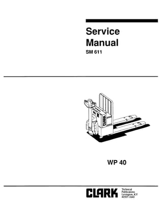
- 6. 0.1 Truck Identification This repair manual covers the following Clark Products: WP-40 Low Lift Pallet Trucks from serial number WP40- l-8 163 and above. Clark reserves the right to change the information and specifications contained within this manual at any time without incurring any obligation relating to such changes. o-1
- 7. 0.2 System Operation Federal and State laws require that operators be completely trained in the safe operation of lift trucks. An Operator’s Manual is attached to every Clark lift truck when it is manufactured. If the Operator’s Manual is missing from the truck a new manual may be obtained by contacting Clark Technical Publication by Fax at 414 79% 8757. This manual is not a training manual. The information contained in this service manual is intended as a guide to help the authorized technician safely repair the truck. o-2
- 8. 0.3 I. Specifications Specifications A. Electrical - Maximum AMP Draw 1. Drive Motor Armature - Cable A2 12 volt 2. a) In Top Variable Speed Lift Pump Motor - Cable Al a) Against Pressure Relief B. C. F. Hydraulic System 1. Type of Fluid 2. Capacity Tires and Wheels 1. Drive Tire 2. Load Wheels Fluids and Lubricants 1. Hydraulic Fluid a) Standard b) Freezer application 2. Lubricating Grease 3. Transmission Oil 71A 24 volt 45A 200A 115A Hydo 32 (standard) Texaco 15 (Freezer only) Approx. 1 quart 10.5 x 5 x 6.5 inches 3.25 x 5 inches HYDO 32 Texaco 15 Texas Refineries C & C #880 85W 90 API GL5 o-3
- 10. INTRODUCTION Threaded fasteners like bolts, nuts, capscrews and studs are made to specifications that describe the mechanical strength and hardness of the fastener. A fastener used in a &sign application is selected according to its specifications. Clark buyspartsfrom many countries. There are several standards used by these countries in the manufacture of threaded fasteners. Many of these fasteners are similar, but cannot be used as direct replacement. Service persons must use replacement fasteners that have the same specifications. Fasteners made to each specification have identification marks for that specification. This specification is commonly called “Grade” for SAE standards and “property” for metric standards. This section describes the identification of some common fasteners. The metric system used by Clark is described as SI (International System of Units, also called SI in all languages). The SI system of measurement is described in IS0 Standard looo, 1973. NOMENCLATURE, THREADS The thread design is specified by a series of numbers and letters for inch and metric fasteners. (See Figure 1). The diameter of the shank of the fastener is shown first in the series [M12= 12mm, M20=20mm (l/2= l/2 inch, 3/4=3/4 inch)]. The number of threads per inch is normally not shown for inch nomenclature and only the UNC (Unified National Coarse) or UNF (Unified National Fine) is shown. This number of threads per inch is not shown because a UNC or UNF fastener has a standard number of threads per inch for a specific diameter. The length of a shank is often indicated as part of the description of a fastener. This length is shown in inches for inch fasteners and in millimeters for metric fasteners. A capscrew will have the following description: A = SHANK DIAMETER B = NUMBER OF THREADS PER B = PITCH UNIT OF LENGTH C = LENGTH C = TYPE OF THREAD FIGURE 1 - THREAD DESIGN Hx 13UNC THREAD (DILL x NO OF THREADS PER INCH) u.s --- -_----- METRIC Ml 2 I 1.75 mm _THREAD (mm DIA. I THREAD PITCH mm) O-6
- 11. STRENGTH IDENTIFICATION The most common property classes for metric fasteners are 8.8 and 10.9. The property class is marked with a number on the head of the capscrew or on a nut. Property classes less then 8.8 are often not marked. Grades for inch bolts go from 2 to 8. Grade 2 fasteners normally do not have marks. The following tables show the marks that identify the grades and property classes for different fasteners. ALWARNINGWhen fasteners must be replaced, the new fasteners must be of the same strength or greater then the original fasteners. The new fasteners must also be the correct size. NOTE: IDENTIFICATION MARKS ARE ACCORDING TO BOLT STRENGTH. THE HIGHER THE NUMBER OR THE INCREASE IN THE NUMBER OF MARKS INDICATES INCREASED BOLT STRENGTH. TABLE 1 - BOLTS AND SCREWS TYPE OF FASTENER I INCH FASTENERS. SIILt4GTHLLYELI’ ,AI C”..DLS + MARKINGS NOT REOUIRED HEX HEAD BOLTS & CAPSCREWS I FLANGE SCREWS I 2.POINT FLANGE SCREWS 1 HEX SOCKET HEAD CAPSCREWS MARKINGS NOT REOUIRED 5.1 METRIC FASTENERS. sT”LWG,” LfWL) rROPLRlr CL.ssES *’ MARKINGS NOT REQUIRED 9.6 109 12 9 MARKINGS SAME AS ABOVE 8.6 12 9 fJ 112.0 4e.* 9.8 @@ o-7
- 12. TABLE 2 - STUDS AND NUTS TYPE OF INCH FASTENERS. METRIC FASTENERS. STRLNGfn LEVELS. SAE GRADES FASTENER STREI(QlHLEVELS PROPERTY CLASSES ilc MARKINGS NOT REQUIRED +k MARKINGS NOT REQUIRED 4.e* 66 @&jQ 9.8 10.9 12.9 - STUDS 6 0 Q @ @ iz!iF LARGER ‘I. OR@@@@ OPTIONAL GEOMETRIC SYMBOLS FOR SIZES M5 THRU Ml 1 ONLY. 5 8 9 MARKINGS NOT REQUIRED iEX SLOlTED NUTS MARKINGS NOT REQUIRED HEX FL4NGE NUTS O-8
- 13. TABLE 3 - TORQUE NUTS TYPE OF FASTENER INCH FASTENERS. METRIC FASTENERS. STIIENGTWLEVELS.s*E tm*ms CTlLnGTHLLYLLI’CnowiRTVCLASSES m &f=jg& &J&J& ALL METAL PRE- VAILING-TOROUE NUTS f G OR m M'.@ (-@ OR ALL METAL PRE- VAILING-TORQUE B3B FLANGE NUTS o-9
- 14. TABLE 4 - TORQUE NUTS WITH NYLON INSERT TYPE OF FASTENER INCH FASTENERS. METRIC FASTENERS. STREHGIHLEVELS SAE GRADES STRLNGTI( LEVCLS.PROPCRTY CLASSES MARKINGS NOT REQUIRED NYLON INSERT PRE- VAILING-TORQUE NUTS MARKINGS NOT REWIRED OR NYLON INSERT PRE- VAILING-TOROUE FLANGE NUTS O-10
- 15. TABLE 5 CONVERSION TABLE FOR METRIC AND ENGLISH UNITS MULTIPLY BY TO GET AREA MULTIPLY BY TO GET LINEAR MULTIPLY BY TO GET MULTIPLY BY TO GET MASS MULTIPLY BY TO GET MULTIPLY BY TO GET POWER MULTIPLY BY TO GET MULTIPLY BY TO GET PRESSURE MULTIPLY BY TO GET MULTIPLY BY TO GET TEMPERATURE MULTIPLY BY TO GET MULTIPLY (“Celsius x 1.8) BY TO GET
- 16. TORQUE IULTIPLY pound inches pound feet BY 0.113 1.356 TO GET Newton meter (N-m) Newton meter fN.m1 MULTIPLY BY TO GET Newton meter 8.851 pound inches (lbf in) Newton meter 0.738 pound feet (lbf in) 4ULTIPLY BY miles/hour 1.609 TO GET MULTIPLY BY TO GET kilometer/hour (km/h) kilometer/hour 0.621 miles/hour Cmvh) VOLUME MULTIPLY BY TO GET MULTIPLY BY TO GET o-12
- 17. -I 3RQUE VALUES FOR COARSE THREAD Zze and Pitchs M5 x 0.8 M6 x 1 MS x 1.25 Ml0 x 1.5 Ml2 x 1.75 Ml4 x 2 Ml6 x 2 M20 x 2.5 M24 x 3 M30 x 3.5 Property, Class 8.8* N.m 5-6 8-10 20-25 40-45 70-80 1lo-125 580-650 Ibf ft Ibf in. 44-53 71-88 177-221 Ibf ft 30-33 428-479 Property, c 10.9** N.m 7-8 12-14 30-35 60-65 100-l 10 155-180 800-900 M36 x 4 TABLE 6 SS lbf ft Ibf in 62-7 1 106-124 Ibf ft 22-26 44-48 KY33 177-199 332-369 590-664 Property, Class 13 a*** I N.m I lbf ft Ibf in 8-10 71-88 14-16 124-142 Ibf ft 34-40 26-30 70-75 52-55 280-320 207-236 550-600 406-443 900-1050 664-774 * Property class 8.8, Protective Treatment CMHC Specification “H” (zinc phosphate), apply also to internally threaded fasteners made of property class 8 material. **Property class 10.9, Protective Treatment CMHC Specification “H” (zinc phosphate), apply also to internally threaded fasteners made of property class 10 material. *** Property class 12.9, Protective Treatment CMHC Specification “H” (zinc phosphate), apply also to internally threaded fasteners of property class 12 material. 3 METRIC FASTENERS o-13
- 18. 0.4 Maintenance and Adjustments 0.4.1 Maintenance Planned Maintenance is a critical part of safe pallet truck operation. By following a regular schedule of planned maintenance procedures the correct and safe functioning of the pallet truck can be better assured. A good planned maintenance program will alert you to the need for adjustments and minor repairs and will greatly reduce the potential for unexpected failures. An effective planned maintenance program will include a daily inspection to be made by the operator prior to each operating shift. This should include a visual inspection for damage, leaks, and fluid levels as well as testing for the correct operation of safety devices. In addition to the operator’s daily inspection a regular scheduled planned maintenance service should be performed by a qualified Clark technician. This service should include a thorough visual inspection, lubrication of service points, operational checks and minor adjustments. The basic planned maintenance visit should be made every 200 operating hours or once a month. More detailed service should be performed once a year. A comprehensive schedule of planned maintenance operations and detailed planned maintenance procedures are in the sections that follow. o-15
- 19. PLANNED MAINTENANCE SCHEDULE SERVICES TO BE PERFORMED DAILY OR AT EACH 8 HOUR OPERATING SHIFT ITEM SERVICE TO BE PERFORMED NOTES BATTERY CHARGE AND CHECK WATER HYDRAULIC SYSTEM INSPECT FOR LEAKS FRAME/SHEET METAL INSPECT FOR LOOSE, DAMAGED, OR MISSING PARTS WHEELS/TIRES INSPECT FOR DAMAGE AND FOR TRASH IN BEARINGS FUNCTIONS/OPERATIONS TEST FOR PROPER OPERATION OF ALL FUNCTIONS EQUALIZE CHARGE ONCE A WEEK ALL SHIELDS MUST BE IN PLACE SAFETY DEVICES MUST FUNCTION SERVICES TO BE PERFORMED EVERY THREE MONTHS OR EVERY 200 OPERATING HOURS I ITEM SERVICE TO BE PERFORMED NOTES II I _Y INSPECTION PERFORM DAILY INSPECTIONS J CHECK FLUID LEVEL ADJUST AS NEEDED CHECK SPECIFIC GRAVITY CHECK FOR TIGHT AND CLEAN DO NOT FILE TIPSCONTACTOR TIPS MOTOR BRUSHES HYDRAULIC RESERVOIR FRAME LUBE PIVOT POINTS DRIVE MOTOR INSPECT FOR ARCING AND PITTING INSPECT FOR MINIMUM LENGTH CHECK FLUID LEVEL LUBRICATE ALL GREASE FITTINGS LUBRICATE ALL PIVOT POINTS BLOW OUT DRIVE MOTOR VENTS DRIP LUBE WITH 10 WT MACHINE OIL COMPRESSED AIR USED FOR CLEANING MUST BE REDUCED TO LESS THAN 30 PSI AND THEN ONLY WITH EFFECTIVE CHIP GUARDING AND PERSONAL PROTECTIVE EQUIPMENT SERVICES TO BE PERFORMED EVERY 2000 OPERATING HOURS ITEM SERVICE TO BE PERFORMED NOTES DAILY INSPECTION PERFORM DAILY INSPECTIONS MONTHLY INSPECTION PERFORM 200 HOUR INSPECTIONS TRANSMISSION D-WIN, FLUSH AND REFILL BA-ITERY REMOVE FROM TRUCK AND CLEAN ALSO CLEAN BATTERY COMPARTMENT HYDRAULIC SYSTEM DRAIN, FLUSH AND REFILL HYDRAULIC SYSTEM SET PRESSURE RELIEF VALVE AND LOAD TEST BRAKES INSPECT BRAKE SHOE WEAR o-1s
- 20. Thank you very much for your reading. Please Click Here. Then Get COMPLETE MANUAL. NO WAITING NOTE: If there is no response to click on the link above, please download the PDF document first and then click on it.
- 21. A B C D F G H HYDRAULIC OIL LEVEL TRANSMISSION PIVOT TUBE HANDLE PIVOT TRANSMISSION OIL LEVEL TRANSMISSION DRAIN PLUG LIFT LINKAGE LOAD WHEEL o-17
- 22. 0.4.3 Planned Maintenance Procedures This section describes how to perform the services listed in the Schedule of Planned Maintenance Operations. As with the “Schedule” this section is sub-divided into service intervals. Services to be performed daily or at each 8 hour operating shift: The daily inspection is to be made by the operator prior to each operating shift. It is the operator’s responsibility to report any defects to the proper authorities and the truck should not be operated until it has been inspected and repaired by a qualified technician. The operator is ultimately responsible for the safe operation of this pallet truck. Battery - The battery should be charged when it reaches the 80% discharged level. This is indicated on the optional Battery Discharge Indicator when the single red LED bar on the far left is illuminated. A warning will be given at the 70% discharged level by means of the two red LED bars flashing alternately on and off. If the truck is equipped with the optional Lift Interrupt then lift lockout will occur at the 80% discharged level. If the optional Battery Discharge Indicator is not mounted then the battery should be charged after 6 to 8 operating hours. Hydraulic System - Inspect the entire truck for leaks; especially around the hydraulic pump assembly and the lift cylinder. Any sign of oil on the floor under the truck is an indication that the truck may be leaking hydraulic oil or transmission fluid. Report any problems to the proper authorities and do not operate the truck until it has been inspected and repaired by a qualified technician. Frame/Sheet Metal - Inspect the truck for loose, damaged or missing parts. All shields must be in place and functional. Report any problems to the proper authorities and do not operate the truck until it has been inspected and repaired by a qualified technician. Wheels/Tires - Inspect wheels and tires for wear and damage. Trash wrapped around wheels and axles will cause premature tire wear and bearing damage. Any trash should be removed before operating the truck and the floors should be kept clear of trash to prevent damage to the wheels and tires. Functions/Operations - Test the truck for the proper operation of all functions; including the travel controls, lift and lower functions, the brakes and the emergency reverser button. Safety devices must be operational. Report any problems to the proper authorities and do not operate the truck until it has been inspected and repaired by a qualified technician. O-18