Caterpillar Cat 930G Wheel Loader (Prefix TWR) Service Repair Manual Instant Download (TWR00001 and up).pdf
1. Product: WHEEL LOADER
Model: 930G WHEEL LOADER TWR
Configuration: 930G Wheel Loader TWR00001-UP (MACHINE) POWERED BY 3056E Engine
Disassembly and Assembly
930G Wheel Loader Power Train
Media Number -RENR8726-03 Publication Date -01/10/2017 Date Updated -09/10/2017
i02247494
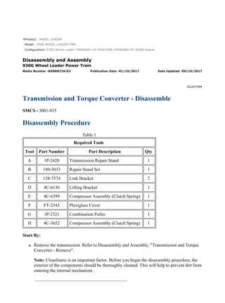
Transmission and Torque Converter - Disassemble
SMCS - 3001-015
Disassembly Procedure
Table 1
Required Tools
Tool Part Number Part Description Qty
A 1P-2420 Transmission Repair Stand 1
B 180-3033 Repair Stand Set 1
C 138-7574 Link Bracket 2
D 4C-6136 Lifting Bracket 1
E 4C-6399 Compressor Assembly (Clutch Spring) 1
F FT-2343 Plexiglass Cover 1
G 1P-2321 Combination Puller 1
H 4C-3652 Compressor Assembly (Clutch Spring) 1
Start By:
a. Remove the transmission. Refer to Disassembly and Assembly, "Transmission and Torque
Converter - Remove".
Note: Cleanliness is an important factor. Before you begin the disassembly procedure, the
exterior of the components should be thoroughly cleaned. This will help to prevent dirt from
entering the internal mechanism.
1/30
930G Wheel Loader TWR00001-UP (MACHINE) POWERED BY 3056E Engine(SE...
2022/5/18
https://127.0.0.1/sisweb/sisweb/techdoc/techdoc_print_page.jsp?returnurl=/sis...
2. Illustration 1 g00653680
1. Use Tooling (C) and a suitable lifting device in order to position transmission (2) on
Tooling (A) and (B), as shown. The weight of transmission (2) is approximately 500 kg
(1100 lb).
2. Remove torque converter (1).
Illustration 2 g00671890
3. Remove bolts (3) and flex plate (4) from torque converter (1).
Illustration 3 g01005185
2/30
930G Wheel Loader TWR00001-UP (MACHINE) POWERED BY 3056E Engine(SE...
2022/5/18
https://127.0.0.1/sisweb/sisweb/techdoc/techdoc_print_page.jsp?returnurl=/sis...
3. 4. Disconnect harness assembly (4A) from the valve assembly.
Illustration 4 g01005186
Note: Mark each valve group for installation purposes.
5. Remove bolts (4B) and remove valve assembly (4C).
6. Repeat Step 5 for the remaining valve assemblies.
Illustration 5 g01005187
7. Remove bolts (4D) from the relief valve. Remove bolts (4E) and remove the manifold
assembly.
3/30
930G Wheel Loader TWR00001-UP (MACHINE) POWERED BY 3056E Engine(SE...
2022/5/18
https://127.0.0.1/sisweb/sisweb/techdoc/techdoc_print_page.jsp?returnurl=/sis...
4. Illustration 6 g00653775
8. Remove bolts (5) and plate (6).
Illustration 7 g00653801
9. Remove lip seal (7) and seal (8).
Illustration 8 g00653806
10. Remove bolts (9).
4/30
930G Wheel Loader TWR00001-UP (MACHINE) POWERED BY 3056E Engine(SE...
2022/5/18
https://127.0.0.1/sisweb/sisweb/techdoc/techdoc_print_page.jsp?returnurl=/sis...
6. Illustration 12 g00653858
15. Using Tooling (D) to remove the forward low and the forward high clutch group (15). The
weight of the forward low and the forward high clutch group (15) is approximately 27 kg
(60 lb).
Note: When the clutch groups are disassembled, remove shaft plugs (16) in order to clean
the oil passages. Use a punch to drive the plug into the shaft . Drill the remainder of the
aluminum plug out of the bore. Be careful not to drill any portion of the walls of the bore.
Use shop air or a cleaning solution in order to clean the shafts.
Illustration 13 g00653893
16. Remove retaining ring (17) and washer (18).
6/30
930G Wheel Loader TWR00001-UP (MACHINE) POWERED BY 3056E Engine(SE...
2022/5/18
https://127.0.0.1/sisweb/sisweb/techdoc/techdoc_print_page.jsp?returnurl=/sis...
7. Illustration 14 g00653932
17. Remove retaining ring (19).
18. Use a suitable press in order to remove gear (20).
Illustration 15 g00890607
19. Remove retaining ring (22). Remove hub (21). Remove plates and discs (23).
Note: Take note of the number and order of plates and discs for assembly purposes.
Illustration 16 g00653959
20. Remove washer (24).
Note: The retainer may stick to the inside of hub (21) when the hub is removed.
7/30
930G Wheel Loader TWR00001-UP (MACHINE) POWERED BY 3056E Engine(SE...
2022/5/18
https://127.0.0.1/sisweb/sisweb/techdoc/techdoc_print_page.jsp?returnurl=/sis...
8. Illustration 17 g00890608
21. Remove retaining ring (26). Press bearing (25) from hub (22).
Illustration 18 g00654018
Personal injury can result from being struck by parts propelled by a
released spring force.
Make sure to wear all necessary protective equipment.
Follow the recommended procedure and use all recommended tooling to
release the spring force.
22. Put the forward low clutch group in a suitable press. Use Tooling (H) in order to compress
the spring. Remove retaining ring (27).
8/30
930G Wheel Loader TWR00001-UP (MACHINE) POWERED BY 3056E Engine(SE...
2022/5/18
https://127.0.0.1/sisweb/sisweb/techdoc/techdoc_print_page.jsp?returnurl=/sis...
9. Illustration 19 g00654029
23. Remove retainer (28) and spring (29).
Illustration 20 g00890609
24. Blow shop air 276 kPa to 414 kPa (40 psi to 60 psi) into lube passage (31) in order to
remove piston (32).
25. Remove seals (30).
Illustration 21 g00654063
26. Remove O-ring seals (33).
9/30
930G Wheel Loader TWR00001-UP (MACHINE) POWERED BY 3056E Engine(SE...
2022/5/18
https://127.0.0.1/sisweb/sisweb/techdoc/techdoc_print_page.jsp?returnurl=/sis...
10. Illustration 22 g00654078
27. Disassemble the forward high clutch group by removing retaining ring (34). Remove
washer (35).
Illustration 23 g00654253
28. Remove ring (36). Remove gear (37).
Illustration 24 g00654261
29. Remove hub (38).
10/30
930G Wheel Loader TWR00001-UP (MACHINE) POWERED BY 3056E Engine(S...
2022/5/18
https://127.0.0.1/sisweb/sisweb/techdoc/techdoc_print_page.jsp?returnurl=/sis...
11. Illustration 25 g00654263
30. Remove retaining ring (39). Use a suitable press in order to remove bearing (40).
Illustration 26 g00654274
31. Remove washer (41). Remove retaining ring (42). Remove the plate and discs (43).
Note: Take note of the number and order of plates and discs for assembly purposes.
Illustration 27 g00654276
11/30
930G Wheel Loader TWR00001-UP (MACHINE) POWERED BY 3056E Engine(S...
2022/5/18
https://127.0.0.1/sisweb/sisweb/techdoc/techdoc_print_page.jsp?returnurl=/sis...
12. Personal injury can result from being struck by parts propelled by a
released spring force.
Make sure to wear all necessary protective equipment.
Follow the recommended procedure and use all recommended tooling to
release the spring force.
32. Put the forward high clutch group in a suitable press. Use Tooling (H) in order to remove
retaining ring (44).
Illustration 28 g00654280
Illustration 29 g00654282
33. Remove retainer (45) and spring (46).
34. Blow shop air 276 kPa to 414 kPa (40 psi to 60 psi) into lube passage (48) in order to
remove piston (47).
12/30
930G Wheel Loader TWR00001-UP (MACHINE) POWERED BY 3056E Engine(S...
2022/5/18
https://127.0.0.1/sisweb/sisweb/techdoc/techdoc_print_page.jsp?returnurl=/sis...
13. Illustration 30 g00654292
35. Remove O-ring seals (49) and (50).
Illustration 31 g00654301
36. Use Tooling (D) in order to remove reverse second gear clutch group (51). The weight of
reverse second gear clutch group (51) is approximately 32 kg (70 lb).
Illustration 32 g00654339
37. Remove retaining ring (52) and washer (53).
13/30
930G Wheel Loader TWR00001-UP (MACHINE) POWERED BY 3056E Engine(S...
2022/5/18
https://127.0.0.1/sisweb/sisweb/techdoc/techdoc_print_page.jsp?returnurl=/sis...
14. Illustration 33 g00654328
38. Remove retaining ring (54) and gear (55).
Illustration 34 g00654347
39. Remove hub assembly (56).
Illustration 35 g00890610
40. Remove washer (58).
41. Remove retaining ring (57). Remove plates and discs (59).
Note: Take note of the number and order of the plates and discs for assembly purposes.
14/30
930G Wheel Loader TWR00001-UP (MACHINE) POWERED BY 3056E Engine(S...
2022/5/18
https://127.0.0.1/sisweb/sisweb/techdoc/techdoc_print_page.jsp?returnurl=/sis...
15. Illustration 36 g00890611
42. Remove retaining ring (60). Use a suitable press in order to remove bearing (61).
Illustration 37 g00654360
Personal injury can result from being struck by parts propelled by a
released spring force.
Make sure to wear all necessary protective equipment.
Follow the recommended procedure and use all recommended tooling to
release the spring force.
43. Put the reverse clutch group in a suitable press. Use Tooling (H) in order to remove
retaining ring (62).
15/30
930G Wheel Loader TWR00001-UP (MACHINE) POWERED BY 3056E Engine(S...
2022/5/18
https://127.0.0.1/sisweb/sisweb/techdoc/techdoc_print_page.jsp?returnurl=/sis...
16. Illustration 38 g00654364
44. Remove retainer (63) and spring (64).
Illustration 39 g00654372
Illustration 40 g00654378
45. Blow shop air 276 kPa to 414 kPa (40 psi to 60 psi) into lube passage (66) in order to
remove piston (65).
46. Remove seals (67).
16/30
930G Wheel Loader TWR00001-UP (MACHINE) POWERED BY 3056E Engine(S...
2022/5/18
https://127.0.0.1/sisweb/sisweb/techdoc/techdoc_print_page.jsp?returnurl=/sis...
17. Illustration 41 g00654403
47. Remove O-ring seals (68) and (69).
Illustration 42 g00890612
48. Install a suitable puller under gear (72). Pull gear (72), spacer (70), and bearing cone (71).
49. Remove spacer (73). Remove washer (74) and (75).
Note: Use Steps 38 through 47 for the remaining disassembly of the second gear clutch
group. In Step 43, use Tooling (E) instead of Tooling (H).
Illustration 43 g00654494
17/30
930G Wheel Loader TWR00001-UP (MACHINE) POWERED BY 3056E Engine(S...
2022/5/18
https://127.0.0.1/sisweb/sisweb/techdoc/techdoc_print_page.jsp?returnurl=/sis...
18. 50. Use Tooling (D) in order to remove first third gear clutch group (76). The weight of first
third gear clutch group (76) is approximately 50 kg (110 lb).
Illustration 44 g00654497
51. Remove retaining ring (77) and washer (78).
Illustration 45 g00654507
52. Remove retaining ring (79) and gear (80).
Illustration 46 g00654512
53. Remove hub assembly (81).
18/30
930G Wheel Loader TWR00001-UP (MACHINE) POWERED BY 3056E Engine(S...
2022/5/18
https://127.0.0.1/sisweb/sisweb/techdoc/techdoc_print_page.jsp?returnurl=/sis...
19. Illustration 47 g00890613
54. Remove retaining ring (82). Use a suitable press in order to remove bearing (83).
Illustration 48 g00654519
55. Remove washer (84).
56. Remove retaining ring (85). Remove plates and discs (86).
Note: Take note of the number and order of the plates and discs for assembly purposes.
Illustration 49 g00654525
19/30
930G Wheel Loader TWR00001-UP (MACHINE) POWERED BY 3056E Engine(S...
2022/5/18
https://127.0.0.1/sisweb/sisweb/techdoc/techdoc_print_page.jsp?returnurl=/sis...
20. Personal injury can result from being struck by parts propelled by a
released spring force.
Make sure to wear all necessary protective equipment.
Follow the recommended procedure and use all recommended tooling to
release the spring force.
57. Put the third gear clutch group in a suitable press. Use Tooling (H) in order to remove ring
(87).
Illustration 50 g00654534
58. Remove retainer (88) and spring (89).
Illustration 51 g00890615
59. Blow shop air 276 kPa to 414 kPa (40 psi to 60 psi) into lube passage (91) in order to
remove piston (90).
60. Remove seals (92).
20/30
930G Wheel Loader TWR00001-UP (MACHINE) POWERED BY 3056E Engine(S...
2022/5/18
https://127.0.0.1/sisweb/sisweb/techdoc/techdoc_print_page.jsp?returnurl=/sis...
21. Illustration 52 g00654638
61. Remove O-ring seals (93) and (94).
Illustration 53 g00890617
62. Disassemble the first gear clutch by installing Tooling (G) through the holes in gear (95).
Pull gear (95), washer (96), and bearing (97) together.
Illustration 54 g00654719
63. Remove washer (98). Remove retaining ring (99) and gear (100).
21/30
930G Wheel Loader TWR00001-UP (MACHINE) POWERED BY 3056E Engine(S...
2022/5/18
https://127.0.0.1/sisweb/sisweb/techdoc/techdoc_print_page.jsp?returnurl=/sis...
22. Illustration 55 g00654724
64. Remove hub assembly (101).
Illustration 56 g00890619
65. Remove washers (102) and (104). Remove retaining ring (103). Remove plates and discs
(105).
Note: Take note of the number and order of the plates and discs for assembly purposes.
Illustration 57 g00654818
66. Remove ring (106).
22/30
930G Wheel Loader TWR00001-UP (MACHINE) POWERED BY 3056E Engine(S...
2022/5/18
https://127.0.0.1/sisweb/sisweb/techdoc/techdoc_print_page.jsp?returnurl=/sis...
23. Illustration 58 g00654824
67. Remove bearing assembly (107).
Illustration 59 g00654833
Personal injury can result from being struck by parts propelled by a
released spring force.
Make sure to wear all necessary protective equipment.
Follow the recommended procedure and use all recommended tooling to
release the spring force.
68. Put the clutch group in a suitable press. Use Tooling (H) in order to remove retaining ring
(108).
23/30
930G Wheel Loader TWR00001-UP (MACHINE) POWERED BY 3056E Engine(S...
2022/5/18
https://127.0.0.1/sisweb/sisweb/techdoc/techdoc_print_page.jsp?returnurl=/sis...
24. Illustration 60 g00654837
69. Remove the retainer and seal assembly (109).
Illustration 61 g00654842
70. Remove spring (110).
Illustration 62 g00654966
71. Blow shop air 276 kPa to 414 kPa (40 psi to 60 psi) into the lube passage in order to remove
piston (111).
24/30
930G Wheel Loader TWR00001-UP (MACHINE) POWERED BY 3056E Engine(S...
2022/5/18
https://127.0.0.1/sisweb/sisweb/techdoc/techdoc_print_page.jsp?returnurl=/sis...
25. Suggest:
For more complete manuals. Please go to
the home page.
https://www.ebooklibonline.com
If the above button click is invalid. Please
download this document first, and then
click the above link to download the
complete manual.
Thank you so much for reading
26. Illustration 63 g00654969
72. Remove seals (112), (113), and (114).
Illustration 64 g00655016
73. Remove input shaft assembly (115).
Illustration 65 g00890621
74. Remove carrier (117) and seal (116). Remove bearing cone (121) and gear (120).
75. Remove bearing cone (118) and gear (119).
25/30
930G Wheel Loader TWR00001-UP (MACHINE) POWERED BY 3056E Engine(S...
2022/5/18
https://127.0.0.1/sisweb/sisweb/techdoc/techdoc_print_page.jsp?returnurl=/sis...
27. Illustration 66 g00655110
76. Remove bearing (122) and bearing cups (123).
Illustration 67 g00655120
77. Remove bolt (124), washer (125), and yoke (126).
Illustration 68 g00685060
78. Remove the bolt and washer (127).
26/30
930G Wheel Loader TWR00001-UP (MACHINE) POWERED BY 3056E Engine(S...
2022/5/18
https://127.0.0.1/sisweb/sisweb/techdoc/techdoc_print_page.jsp?returnurl=/sis...