SlideShare a Scribd company logo
1 of 6
Download to read offline
GROUP

RM

Roxtec SBTB frame
The Roxtec SBTB frame is
a metal frame with two packing spaces behind each other (backto-back). The SBTB frame has been
designed to meet high levels of fire
protection and for easy verification
of pressure tightness after installation.

Roxtec SBTB-kehys
on metallikehys, jossa on
kaksi pakkaustilaa peräkkäin
(back-to-back). SBTB-kehys on
kehitetty vastaamaan paloturvallisuuden korkeita vaatimuksia ja
mahdollistamaan painetiiveyden
varmistamisen asennuksen jälkeen.

■ For use with two sets of Group
RM components
■ Pressure test pipe available
■ Attachment by welding

■ Käytetään kahden RM-tuoteryhmän komponenttien kanssa
■ Painetestinippa saatavilla
■ Kiinnitetään hitsaamalla

Roxtec SBTB är en metallram
med två packningsutrymmen
efter varandra (back-to-back). SBTB
är speciellt framtagen för att möta
höga brandkrav och för möjligheten
att kontrolltrycka tätningen efter
installation.

Il telaio SBTB (back-to-back,
dorso a dorso) di Roxtec è
un telaio metallico con due spazi
di riempimento l’uno alle spalle
dell’altro (back-to-back).” L’SBTB è
stato ideato per garantire alti livelli
di protezione contro gli incendi e per
facilitare il controllo della tenuta alla
pressione dopo l’installazione.

GB

Рама SBTB от Roxtec металлическая рама c двумя
проемами для уплотнения,
расположенными один за другим. SBTB
была разработана для обеспечения
высокой степени огнестойкости и
возможности быстрой проверки на
герметичность после монтажа.

RU

■ Для использования с двумя
комплектами компонентов
группы RM
■ Для проверки герметичности
предлагается специальный ниппель
■ Крепление сваркой

54

www.roxtec.com

SE

■ För användning med två satser
komponenter ur Grupp RM
■ Teströr finns som tillbehör
■ Infästning genom svetsning

FI

IT

■ Raccordo per il test di pressione
disponibile
■ Per due set di componenti del
gruppo RM
■ Fissaggio mediante saldatura
GROUP

RM

SBTB frames, primed, mild steel
SBTB-kehykset, pohjamaalattu teräs ❱ Рама SBTB, окрашенная, стальная ❱ SBTB-ramar, lackerat konstruktionsstål ❱
Telaio SBTB, in acciaio con prima mano d’antiruggine
Parts needed for a complete solution

page 22

page 137

page 141

page 145

See also Installation guidelines on page 203.

For information about other frame combinations that are not
presented, please contact your local Roxtec supplier or e-mail:
info@roxtec.com

SBTB 6x1 primed

RATINGS

FI
RU
SE
IT
GB

Fire: A-Class, H-Class

Kehys

Aukkojen
lukumäärä

Рама

Количество
проёмов

Ram
Telaio
Frame

SBTB 2x1 primed

Water pressure: 4 bar

Pakkaustila (mm)

Gas pressure: 2.5 bar

Ulkomitat (D=200 mm)
HxW (mm)
HxW (in)

Ramöppningar

Зона уплотнения
(мм)
Packningsutrymme (mm)

Внешние размеры (D=200 мм)
HxW (мм)
HxW (дюйм)
Yttermått (D=200 mm)
HxW (mm)
HxW (tum)

Aperture
telaio
Frame
openings

Spazio di riempimento (mm)
Packing space
(mm)

Dimensioni esterne (D=200 mm)
HxW (mm)
HxW (tum)
External dimensions (D=200 mm)
HxW (mm)
HxW (in)

1

60 x 120

121 x 141

4.764 x 5.531

Paino
(kg)

(lb)

Tuotenumero

Вес
(кг)

(фунт)

Арт. №

Vikt
(kg)

(lb)

Artikelnummer

(lb)

Art.Nr.

(lb)

Art. No.

Peso
(kg)
Weight
(kg)

7.2

15.939

5SBT000003961

SBTB 2x2 primed

2

60 x 120

121 x 271

4.764 x 10.669

12.0

26.389

SBTB020000212

SBTB 2x3 primed

3

60 x 120

121 x 402

4.764 x 15.827

16.7

36.839

SBTB020000312

SBTB 2x4 primed

4

60 x 120

121 x 532

4.764 x 20.945

21.5

47.289

SBTB020000412

SBTB 4x1 primed

1

120 x 120

180 x 141

7.087 x 5.531

8.9

19.709

5S00000004392

SBTB 4x2 primed

2

120 x 120

180 x 271

7.087 x 10.669

14.2

31.372

SBTB040000212

SBTB 4x3 primed

3

120 x 120

180 x 402

7.087 x 15.807

19.5

43.034

SBTB040000312

SBTB 4x4 primed

4

120 x 120

180 x 532

7.087 x 20.945

24.8

54.697

SBTB040000412

SBTB 4x5 primed

5

120 x 120

180 x 663

7.087 x 26.083

30.1

66.359

SBTB040000512

SBTB 4x6 primed

6

120 x 120

180 x 793

7.087 x 31.220

35.4

78.022

SBTB040000612

SBTB 6x1 primed

1

180 x 120

238 x 141

9.370 x 5.531

10.6

23.479

5S00000004391

SBTB 6x2 primed

2

180 x 120

238 x 271

9.370 x 10.669

16.5

36.354

5S00000004503

SBTB 6x3 primed

3

180 x 120

238 x 402

9.370 x 15.807

22.3

49.229

5S00000004393

SBTB 6x4 primed

4

180 x 120

238 x 532

9.370 x 20.945

28.2

62.104

5S00000004394

SBTB 6x5 primed

5

180 x 120

238 x 663

9.370 x 26.083

34.0

74.979

5S00000004528

SBTB 6x6 primed

6

180 x 120

238 x 793

9.370 x 31.220

39.9

87.854

5S00000004500

SBTB 8x1 primed

1

240 x 120

298 x 141

11.732 x 5.531

12.4

27.337

SBTB080000112

SBTB 8x2 primed

2

240 x 120

298 x 271 11.732 x 10.669

18.8

41.469

SBTB080000212

SBTB 8x3 primed

3

240 x 120

298 x 402 11.732 x 15.807

25.2

55.579

SBTB080000312

SBTB 8x4 primed

4

240 x 120

298 x 532 11.732 x 20.945

31.6

69.710

SBTB080000412

www.roxtec.com

55
RM

GROUP

SBTB frames, technical information
SBTB-kehysten tekniset tiedot ❱ Рама SBTB, техническая информация ❱ SBTB-ramar, teknisk information ❱
Telai SBTB, informazioni tecniche

A

H
h

R

H
h

t

A

A
t

d

w
W

d
A-A

(mm)
H - 20

(in)
H - 0.787

w

W - 20

W - 0.787

D

200

7.874

d

60

2.362

t

10

0.394

R 10

R 0.394

R

A

SBTB ZxN

SBTB Zx1

Pos
h

t
w
W

D

Z = Frame size
N = Number of horizontal openings
Z = Kehyksen koko
N = Aukkojen lukumäärä vaakasuunnassa
Z - Размер рамы
N - Количество проемов/секций по горизонтали
Z = Ramstorlek
N = Antal öppningar i bredd
Z = Grandezza telaio
N = Numero delle aperture orizzontali

Note: All dimensions are nominal values
Huomaa: Kaikki mitat ovat nimellisarvoja
Внимание: Все размеры номинальные
Obs: Alla mått är nominella
Nota: tutte le dimensioni sono valori nominali

56

www.roxtec.com

d

d
D
A-A
Welding

GROUP

RM S, SRC, SK and SBTB frame, welding guidelines

S-, SRC-, SK ja SBTB-kehysten hitsausohjeet
S, SRC, SK и SBTB рамы, Инструкция по привариванию
S-, SRC-, SK- och SBTB-ram, riktlinjer för insvetsning
Telai S, SRC, SK e SBTB, linee guida per la saldatura

Min. space for stayplates
Min. tila välilevyjä varten.
Минимальное пространство для разделительной пластины
Min. frigång för stagbrickor
Spazio min. per le piastre d’ancoraggio

Welding sequence in bulkhead or deck
Hitsausjärjestys kanteen tai laipioon
Очередность приваривания на палубу или переборку
Svetsföljd i skott eller däck
Procedura di saldatura su paratia e ponte
Tack weld 1
Hitsi 1 suunta
Прихваточная точка сварки 1
Häftsvets 1
Saldatura 1

3
1

End point / Tack weld 3
Lopetuspiste / Hitsi 3
Точка завершения / точка сварки 3
Slutpunkt / Häftsvets 3
Punto finale / Saldatura 3

5
5 mm, 0197”
3

Welding pass
Hitsauksen kulku
Сварочный шов
Svetssträng
Saldatura

Max root gap for fillet joint.

Максимальное расстояние от рамы до
перегородки

Наплавка соединительного шва.
Наплавка должна быть сделана на
переборке или палубе. Важно: зазор
между свариваемыми кромками
должен быть как можно меньше для
сохранения допуска в проеме.

Spazio max. per il cordone di
saldatura

www.roxtec.com

6

Пример двух- проходного сварного шва.
Exemplen visar två sekvenser kälsvets.
Gli esempi descrivono un doppio cordone
di saldatura.

Max 2 mm, 0.079"

Voitelu tulee suorittaa kanteen tai
laipioon. Tärkeää: Raon on oltava
mahdollisimman pieni aukkojen
toleranssien säilyttämiseksi.

214

(A, C, D, F)

Esimerkit havainnollistavat kahden pienahitsin kulkua.

Buttering should be performed on the
deck or bulkhead. Important: The root
gap must be as small as possible to
keep the tolerance of the openings.

Il cordone di saldatura deve essere
fatto sulla paratia. Importante: Lo
spazio deve essere il più stretto
possibile per garantire la tolleranza
delle aperture.

5 mm, 0197”
4

The examples depict two passes fillet weld.

Welding pass
Hitsauksen kulku
Сварочный шов
Svetssträng
Saldatura

Påsvetsning (stumsvetsning) bör
utföras på däcket eller skottet.
Viktigt: svetsspalten måste göras så
liten som möjligt för att klara toleransen för ramöppningen.

6

2

5

1-2 mm, 0.039"-0.079"

(B, E)

2

1

Start point / Tack weld 2
Aloituspiste / Hitsi 2
Прихваточная точка сварки 2
Startpunkt / Häftsvets 2
Punto iniziale / Saldatura 2

4

Maks. pienan liitoksen rako.

Max spalt för insvetsning.

Important: Weld pass no. 5-6 are not to be
started until welding no. 1-4 are completed
and the temperature of welding pass
no.1-4 has cooled down to min. pre-heat
temperature.
Tärkeää: Hitsauksen kohtia 5-6 ei tule
aloittaa ennen kuin hitsaus kohdissa 1-4
on valmis ja kunnes lämpötila hitsauksen
kohdissa 1-4 on viilentynyt minimi
esikuumennuslämpötilaan.
Внимание: Нельзя продолжать сварку шва в
точках 5-6, пока не остынет шов от точки 1 до
точки 4.
Obs: Svetssträng nr 5-6 startas efter att
svets 1-4 är avslutade och temperaturen på
svets 1-4 har minskat till min. förvärmningstemperatur.
Importante: non cominciare le saldature
5 e 6 prima che le saldature 1 e 4 siano
completate e le temperature ridiscendano
alla temperatura di preriscaldamento
minimo.
RM

S-, SRC-, SK ja SBTB-kehysten hitsausohjeet
S, SRC, SK и SBTB рамы, Инструкция по привариванию
S-, SRC-, SK- och SBTB-ram, riktlinjer för insvetsning
Telai S, SRC, SK e SBTB, linee guida per la saldatura

Fillet weld / Pienahitsi / Сварной шов / Kälsvets / Cordone di saldatura –
weld sizes / hitsin koot / размеры шва / storlek / dimensione del cordone di saldatura
T1 (Frame / Kehys /
рама / Ram / Telai)

T2 (Bulkhead/Deck / Laipio/
Kansi / Переборка/Палуба /
Skott/Däck / Paratia/Ponte)

Fillet weld - weld sizes / Pienahitsi - hitsin koot / Сварной Welding pass / Hitsauksen kulku /
шов - размеры шва / Kälsvets - storlek / Cordone di saldatura - Сварочный шов / Svetssträng /
dimensione del cordone di saldatura
Saldatura
1

2

3

4

5

6

10

>=8

a6

X

X

X

X

X

X

10

>=7

a4

X

X

X

X

(A, C, D, F)

T1

T1

T2

a

a

(B, E)

Possible positions
Mahdolliset asennot
Допустимые положения
Möjliga placeringar
Posizioni possibili

T2

Seal weld (5 & 6)
Hitsauksen liitos (5 & 6)
Укрепляющий сварной шов (5 & 6)
Tätsvets (5 & 6)
Filo di saldatura (5 & 6)

Seal weld (5 & 6)
Hitsauksen liitos (5 & 6)
Укрепляющий сварной шов (5 & 6)
Tätsvets (5 & 6)
Filo di saldatura (5 & 6)

Deck
Kansi
Палуба
Däck
Ponte

A

Bulkhead
Laipio
Переборка
Skott
Paratia

D

E

F

B

C

www.roxtec.com

215

Welding

GROUP

S, SRC, SK and SBTB frame, welding guidelines
Welding

GROUP

RM S, SRC, SK and SBTB frame, welding guidelines

S-, SRC-, SK ja SBTB-kehysten hitsausohjeet
S, SRC, SK и SBTB рамы, Инструкция по привариванию
S-, SRC-, SK- och SBTB-ram, riktlinjer för insvetsning
Telai S, SRC, SK e SBTB, linee guida per la saldatura

GB

Aluminum welding, pre-heat temperature

Combined thickness
(mm)/(in) T1+T2

Minimum pre-heat
temperature

Combined thickness
(mm)/(in) T1+T2

10° C, 50° F
50° C, 122° F

<25/0.984
>25/0.984<50/1.969

10° C, 50° F
50° C, 122° F

Pohjamaalatun teräksen hitsaus,
esikuumennuslämpötila

Alumiinin hitsaus, esikuumennuslämpötila

Yhdistetty vahvuus
(mm) / (in) T1+T2

Minimi
esikuumennuslämpötila

Yhdistetty vahvuus
(mm) / (in) T1+T2

10° C, 50° F
50° C, 122o F

<25/0.984
>25/0.984<50/1.969

10° C, 50° F
50° C, 122o F

Сталь, температура пред- нагрева

Алюминий, температура пред- нагрева

Общая толщина,
мм/дюйм T1+T2

Минимальная
температура нагрева

Общая толщина,
мм/дюйм T1+T2

10° C, 50° F
50° C, 122° F

<25/0.984
>25/0.984<50/1.969

10° C, 50° F
50° C, 122° F

Svets i konstruktionsstål, förvärmningstemperatur

Aluminiumsvetsning, förvärmningstemperatur

Sammanlagd tjocklek
(mm)/(tum) T1+T2

Minimum förvärmningstemperatur

Sammanlagd tjocklek
(mm)/(tum) T1+T2

Minimum förvärmningstemperatur

<50/1.969
>50/1.969<80/3.150

10˚ C, 50˚ F
50˚ C, 122˚ F

<25/0.984
>25/0.984<50/1.969

10˚ C, 50˚ F
50˚ C, 122˚ F

Saldatura acciaio dolce, temperatura
di riscaldamento

saldatura alluminio, temperatura
di riscaldamento

Spessore combinato
(mm)/(in) T1+T2

min. temperatura di
pre-riscaldamento

Spessore combinato
(mm)/(in) T1+T2

10° C, 50° F
50° C, 122° F

<25/0.984
>25/0.984<50/1.969

Svetsning i rostfritt stål, ingen förvärmning

min. temperatura di
pre-riscaldamento

<50/1.969
>50/1.969<80/3.150

IT

Нерж. сталь, без нагрева

Минимальная
температура нагрева

<50/1.969
>50/1.969<80/3.150

SE

Ruostumattoman teräksen hitsaus,
esikuumennusta ei tarvita

Minimi
esikuumennuslämpötila

<50/1.969
>50/1.969<80/3.150

RU

Stainless steel welding, no pre-heat

Minimum pre-heat
temperature

<50/1.969
>50/1.969<80/3.150

FI

Mild steel welding, pre-heat temperature

10° C, 50° F
50° C, 122° F

Saldatura acciaio inox, senza pre-riscaldamento

WWW.CABLEJOINTS.CO.UK

THORNE & DERRICK UK
TEL 0044 191 490 1547 FAX 0044 477 5371
TEL 0044 117 977 4647 FAX 0044 977 5582
WWW.THORNEANDDERRICK.CO.UK

216

www.roxtec.com

More Related Content

More from Thorne & Derrick International

More from Thorne & Derrick International (20)

The Children North East Annual Golf Day Wednesday 9th May 2018
The Children North East Annual Golf Day Wednesday 9th May 2018The Children North East Annual Golf Day Wednesday 9th May 2018
The Children North East Annual Golf Day Wednesday 9th May 2018
 
3M Electrical Products Stocked By Thorne & Derrick International
3M Electrical Products Stocked By Thorne & Derrick International3M Electrical Products Stocked By Thorne & Derrick International
3M Electrical Products Stocked By Thorne & Derrick International
 
CATU Electrical Safety Catalogue
CATU Electrical Safety CatalogueCATU Electrical Safety Catalogue
CATU Electrical Safety Catalogue
 
11kV Cable Termination Heat Shrink Kits 3 Core 16-25sqmm SPS 3TIS-12X-A
11kV Cable Termination Heat Shrink Kits 3 Core 16-25sqmm SPS 3TIS-12X-A11kV Cable Termination Heat Shrink Kits 3 Core 16-25sqmm SPS 3TIS-12X-A
11kV Cable Termination Heat Shrink Kits 3 Core 16-25sqmm SPS 3TIS-12X-A
 
THORNE + DERRICK : LV, MV & HV Cable Installation, Jointing, Substation & Ele...
THORNE + DERRICK : LV, MV & HV Cable Installation, Jointing, Substation & Ele...THORNE + DERRICK : LV, MV & HV Cable Installation, Jointing, Substation & Ele...
THORNE + DERRICK : LV, MV & HV Cable Installation, Jointing, Substation & Ele...
 
Ex d Enclosures - Explosion Proof Hazardous Area Technor EJB Galvanised Steel...
Ex d Enclosures - Explosion Proof Hazardous Area Technor EJB Galvanised Steel...Ex d Enclosures - Explosion Proof Hazardous Area Technor EJB Galvanised Steel...
Ex d Enclosures - Explosion Proof Hazardous Area Technor EJB Galvanised Steel...
 
Roxtec Cable Transit - B Frame Dimensional Drawing
Roxtec Cable Transit - B Frame Dimensional DrawingRoxtec Cable Transit - B Frame Dimensional Drawing
Roxtec Cable Transit - B Frame Dimensional Drawing
 
Pepperl & Fuchs SIL Training Certificate - T&D Adam Rowe
Pepperl & Fuchs SIL Training Certificate - T&D Adam RowePepperl & Fuchs SIL Training Certificate - T&D Adam Rowe
Pepperl & Fuchs SIL Training Certificate - T&D Adam Rowe
 
T&D Experts In Equipment For Explosive Atmospheres
T&D Experts In Equipment For Explosive AtmospheresT&D Experts In Equipment For Explosive Atmospheres
T&D Experts In Equipment For Explosive Atmospheres
 
Ultrasonic Flow Meters - Customer Specification Demand
Ultrasonic Flow Meters - Customer Specification DemandUltrasonic Flow Meters - Customer Specification Demand
Ultrasonic Flow Meters - Customer Specification Demand
 
Emtelle Fibre Optic Cables - Product Catalogue 2016
Emtelle Fibre Optic Cables - Product Catalogue 2016Emtelle Fibre Optic Cables - Product Catalogue 2016
Emtelle Fibre Optic Cables - Product Catalogue 2016
 
Thorne & Derrick Process Heating Brochure 2016
Thorne & Derrick Process Heating Brochure 2016Thorne & Derrick Process Heating Brochure 2016
Thorne & Derrick Process Heating Brochure 2016
 
SIRAI ASCO Numatics Solenoid Valves WRAS Approved - SIRAI L182D L282D
SIRAI ASCO Numatics Solenoid Valves WRAS Approved - SIRAI L182D L282DSIRAI ASCO Numatics Solenoid Valves WRAS Approved - SIRAI L182D L282D
SIRAI ASCO Numatics Solenoid Valves WRAS Approved - SIRAI L182D L282D
 
Ripley Utility Tool Cable Preparation Tools
Ripley Utility Tool Cable Preparation ToolsRipley Utility Tool Cable Preparation Tools
Ripley Utility Tool Cable Preparation Tools
 
RIDGID micro CD100 Combustible Gas Detector
RIDGID micro CD100 Combustible Gas DetectorRIDGID micro CD100 Combustible Gas Detector
RIDGID micro CD100 Combustible Gas Detector
 
Itron Fact Sheet
Itron Fact SheetItron Fact Sheet
Itron Fact Sheet
 
United Nations Environment Programme (UNEP) ‘2006 Report of the Refrigeration...
United Nations Environment Programme (UNEP) ‘2006 Report of the Refrigeration...United Nations Environment Programme (UNEP) ‘2006 Report of the Refrigeration...
United Nations Environment Programme (UNEP) ‘2006 Report of the Refrigeration...
 
Filoform FiloSeal+HD Reenterable LV HV Power Cable Duct Seal System - Spec Sheet
Filoform FiloSeal+HD Reenterable LV HV Power Cable Duct Seal System - Spec SheetFiloform FiloSeal+HD Reenterable LV HV Power Cable Duct Seal System - Spec Sheet
Filoform FiloSeal+HD Reenterable LV HV Power Cable Duct Seal System - Spec Sheet
 
Eltherm Self-Regulating Trace Heating Cables
Eltherm Self-Regulating Trace Heating CablesEltherm Self-Regulating Trace Heating Cables
Eltherm Self-Regulating Trace Heating Cables
 
Temperature Calibrators - Sika Instruments Overview
Temperature Calibrators - Sika Instruments OverviewTemperature Calibrators - Sika Instruments Overview
Temperature Calibrators - Sika Instruments Overview
 

Roxtec Cable Transit Seals - Roxtec SBTB Cable Transit Frame

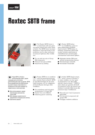
  • 1. GROUP RM Roxtec SBTB frame The Roxtec SBTB frame is a metal frame with two packing spaces behind each other (backto-back). The SBTB frame has been designed to meet high levels of fire protection and for easy verification of pressure tightness after installation. Roxtec SBTB-kehys on metallikehys, jossa on kaksi pakkaustilaa peräkkäin (back-to-back). SBTB-kehys on kehitetty vastaamaan paloturvallisuuden korkeita vaatimuksia ja mahdollistamaan painetiiveyden varmistamisen asennuksen jälkeen. ■ For use with two sets of Group RM components ■ Pressure test pipe available ■ Attachment by welding ■ Käytetään kahden RM-tuoteryhmän komponenttien kanssa ■ Painetestinippa saatavilla ■ Kiinnitetään hitsaamalla Roxtec SBTB är en metallram med två packningsutrymmen efter varandra (back-to-back). SBTB är speciellt framtagen för att möta höga brandkrav och för möjligheten att kontrolltrycka tätningen efter installation. Il telaio SBTB (back-to-back, dorso a dorso) di Roxtec è un telaio metallico con due spazi di riempimento l’uno alle spalle dell’altro (back-to-back).” L’SBTB è stato ideato per garantire alti livelli di protezione contro gli incendi e per facilitare il controllo della tenuta alla pressione dopo l’installazione. GB Рама SBTB от Roxtec металлическая рама c двумя проемами для уплотнения, расположенными один за другим. SBTB была разработана для обеспечения высокой степени огнестойкости и возможности быстрой проверки на герметичность после монтажа. RU ■ Для использования с двумя комплектами компонентов группы RM ■ Для проверки герметичности предлагается специальный ниппель ■ Крепление сваркой 54 www.roxtec.com SE ■ För användning med två satser komponenter ur Grupp RM ■ Teströr finns som tillbehör ■ Infästning genom svetsning FI IT ■ Raccordo per il test di pressione disponibile ■ Per due set di componenti del gruppo RM ■ Fissaggio mediante saldatura
  • 2. GROUP RM SBTB frames, primed, mild steel SBTB-kehykset, pohjamaalattu teräs ❱ Рама SBTB, окрашенная, стальная ❱ SBTB-ramar, lackerat konstruktionsstål ❱ Telaio SBTB, in acciaio con prima mano d’antiruggine Parts needed for a complete solution page 22 page 137 page 141 page 145 See also Installation guidelines on page 203. For information about other frame combinations that are not presented, please contact your local Roxtec supplier or e-mail: info@roxtec.com SBTB 6x1 primed RATINGS FI RU SE IT GB Fire: A-Class, H-Class Kehys Aukkojen lukumäärä Рама Количество проёмов Ram Telaio Frame SBTB 2x1 primed Water pressure: 4 bar Pakkaustila (mm) Gas pressure: 2.5 bar Ulkomitat (D=200 mm) HxW (mm) HxW (in) Ramöppningar Зона уплотнения (мм) Packningsutrymme (mm) Внешние размеры (D=200 мм) HxW (мм) HxW (дюйм) Yttermått (D=200 mm) HxW (mm) HxW (tum) Aperture telaio Frame openings Spazio di riempimento (mm) Packing space (mm) Dimensioni esterne (D=200 mm) HxW (mm) HxW (tum) External dimensions (D=200 mm) HxW (mm) HxW (in) 1 60 x 120 121 x 141 4.764 x 5.531 Paino (kg) (lb) Tuotenumero Вес (кг) (фунт) Арт. № Vikt (kg) (lb) Artikelnummer (lb) Art.Nr. (lb) Art. No. Peso (kg) Weight (kg) 7.2 15.939 5SBT000003961 SBTB 2x2 primed 2 60 x 120 121 x 271 4.764 x 10.669 12.0 26.389 SBTB020000212 SBTB 2x3 primed 3 60 x 120 121 x 402 4.764 x 15.827 16.7 36.839 SBTB020000312 SBTB 2x4 primed 4 60 x 120 121 x 532 4.764 x 20.945 21.5 47.289 SBTB020000412 SBTB 4x1 primed 1 120 x 120 180 x 141 7.087 x 5.531 8.9 19.709 5S00000004392 SBTB 4x2 primed 2 120 x 120 180 x 271 7.087 x 10.669 14.2 31.372 SBTB040000212 SBTB 4x3 primed 3 120 x 120 180 x 402 7.087 x 15.807 19.5 43.034 SBTB040000312 SBTB 4x4 primed 4 120 x 120 180 x 532 7.087 x 20.945 24.8 54.697 SBTB040000412 SBTB 4x5 primed 5 120 x 120 180 x 663 7.087 x 26.083 30.1 66.359 SBTB040000512 SBTB 4x6 primed 6 120 x 120 180 x 793 7.087 x 31.220 35.4 78.022 SBTB040000612 SBTB 6x1 primed 1 180 x 120 238 x 141 9.370 x 5.531 10.6 23.479 5S00000004391 SBTB 6x2 primed 2 180 x 120 238 x 271 9.370 x 10.669 16.5 36.354 5S00000004503 SBTB 6x3 primed 3 180 x 120 238 x 402 9.370 x 15.807 22.3 49.229 5S00000004393 SBTB 6x4 primed 4 180 x 120 238 x 532 9.370 x 20.945 28.2 62.104 5S00000004394 SBTB 6x5 primed 5 180 x 120 238 x 663 9.370 x 26.083 34.0 74.979 5S00000004528 SBTB 6x6 primed 6 180 x 120 238 x 793 9.370 x 31.220 39.9 87.854 5S00000004500 SBTB 8x1 primed 1 240 x 120 298 x 141 11.732 x 5.531 12.4 27.337 SBTB080000112 SBTB 8x2 primed 2 240 x 120 298 x 271 11.732 x 10.669 18.8 41.469 SBTB080000212 SBTB 8x3 primed 3 240 x 120 298 x 402 11.732 x 15.807 25.2 55.579 SBTB080000312 SBTB 8x4 primed 4 240 x 120 298 x 532 11.732 x 20.945 31.6 69.710 SBTB080000412 www.roxtec.com 55
  • 3. RM GROUP SBTB frames, technical information SBTB-kehysten tekniset tiedot ❱ Рама SBTB, техническая информация ❱ SBTB-ramar, teknisk information ❱ Telai SBTB, informazioni tecniche A H h R H h t A A t d w W d A-A (mm) H - 20 (in) H - 0.787 w W - 20 W - 0.787 D 200 7.874 d 60 2.362 t 10 0.394 R 10 R 0.394 R A SBTB ZxN SBTB Zx1 Pos h t w W D Z = Frame size N = Number of horizontal openings Z = Kehyksen koko N = Aukkojen lukumäärä vaakasuunnassa Z - Размер рамы N - Количество проемов/секций по горизонтали Z = Ramstorlek N = Antal öppningar i bredd Z = Grandezza telaio N = Numero delle aperture orizzontali Note: All dimensions are nominal values Huomaa: Kaikki mitat ovat nimellisarvoja Внимание: Все размеры номинальные Obs: Alla mått är nominella Nota: tutte le dimensioni sono valori nominali 56 www.roxtec.com d d D A-A
  • 4. Welding GROUP RM S, SRC, SK and SBTB frame, welding guidelines S-, SRC-, SK ja SBTB-kehysten hitsausohjeet S, SRC, SK и SBTB рамы, Инструкция по привариванию S-, SRC-, SK- och SBTB-ram, riktlinjer för insvetsning Telai S, SRC, SK e SBTB, linee guida per la saldatura Min. space for stayplates Min. tila välilevyjä varten. Минимальное пространство для разделительной пластины Min. frigång för stagbrickor Spazio min. per le piastre d’ancoraggio Welding sequence in bulkhead or deck Hitsausjärjestys kanteen tai laipioon Очередность приваривания на палубу или переборку Svetsföljd i skott eller däck Procedura di saldatura su paratia e ponte Tack weld 1 Hitsi 1 suunta Прихваточная точка сварки 1 Häftsvets 1 Saldatura 1 3 1 End point / Tack weld 3 Lopetuspiste / Hitsi 3 Точка завершения / точка сварки 3 Slutpunkt / Häftsvets 3 Punto finale / Saldatura 3 5 5 mm, 0197” 3 Welding pass Hitsauksen kulku Сварочный шов Svetssträng Saldatura Max root gap for fillet joint. Максимальное расстояние от рамы до перегородки Наплавка соединительного шва. Наплавка должна быть сделана на переборке или палубе. Важно: зазор между свариваемыми кромками должен быть как можно меньше для сохранения допуска в проеме. Spazio max. per il cordone di saldatura www.roxtec.com 6 Пример двух- проходного сварного шва. Exemplen visar två sekvenser kälsvets. Gli esempi descrivono un doppio cordone di saldatura. Max 2 mm, 0.079" Voitelu tulee suorittaa kanteen tai laipioon. Tärkeää: Raon on oltava mahdollisimman pieni aukkojen toleranssien säilyttämiseksi. 214 (A, C, D, F) Esimerkit havainnollistavat kahden pienahitsin kulkua. Buttering should be performed on the deck or bulkhead. Important: The root gap must be as small as possible to keep the tolerance of the openings. Il cordone di saldatura deve essere fatto sulla paratia. Importante: Lo spazio deve essere il più stretto possibile per garantire la tolleranza delle aperture. 5 mm, 0197” 4 The examples depict two passes fillet weld. Welding pass Hitsauksen kulku Сварочный шов Svetssträng Saldatura Påsvetsning (stumsvetsning) bör utföras på däcket eller skottet. Viktigt: svetsspalten måste göras så liten som möjligt för att klara toleransen för ramöppningen. 6 2 5 1-2 mm, 0.039"-0.079" (B, E) 2 1 Start point / Tack weld 2 Aloituspiste / Hitsi 2 Прихваточная точка сварки 2 Startpunkt / Häftsvets 2 Punto iniziale / Saldatura 2 4 Maks. pienan liitoksen rako. Max spalt för insvetsning. Important: Weld pass no. 5-6 are not to be started until welding no. 1-4 are completed and the temperature of welding pass no.1-4 has cooled down to min. pre-heat temperature. Tärkeää: Hitsauksen kohtia 5-6 ei tule aloittaa ennen kuin hitsaus kohdissa 1-4 on valmis ja kunnes lämpötila hitsauksen kohdissa 1-4 on viilentynyt minimi esikuumennuslämpötilaan. Внимание: Нельзя продолжать сварку шва в точках 5-6, пока не остынет шов от точки 1 до точки 4. Obs: Svetssträng nr 5-6 startas efter att svets 1-4 är avslutade och temperaturen på svets 1-4 har minskat till min. förvärmningstemperatur. Importante: non cominciare le saldature 5 e 6 prima che le saldature 1 e 4 siano completate e le temperature ridiscendano alla temperatura di preriscaldamento minimo.
  • 5. RM S-, SRC-, SK ja SBTB-kehysten hitsausohjeet S, SRC, SK и SBTB рамы, Инструкция по привариванию S-, SRC-, SK- och SBTB-ram, riktlinjer för insvetsning Telai S, SRC, SK e SBTB, linee guida per la saldatura Fillet weld / Pienahitsi / Сварной шов / Kälsvets / Cordone di saldatura – weld sizes / hitsin koot / размеры шва / storlek / dimensione del cordone di saldatura T1 (Frame / Kehys / рама / Ram / Telai) T2 (Bulkhead/Deck / Laipio/ Kansi / Переборка/Палуба / Skott/Däck / Paratia/Ponte) Fillet weld - weld sizes / Pienahitsi - hitsin koot / Сварной Welding pass / Hitsauksen kulku / шов - размеры шва / Kälsvets - storlek / Cordone di saldatura - Сварочный шов / Svetssträng / dimensione del cordone di saldatura Saldatura 1 2 3 4 5 6 10 >=8 a6 X X X X X X 10 >=7 a4 X X X X (A, C, D, F) T1 T1 T2 a a (B, E) Possible positions Mahdolliset asennot Допустимые положения Möjliga placeringar Posizioni possibili T2 Seal weld (5 & 6) Hitsauksen liitos (5 & 6) Укрепляющий сварной шов (5 & 6) Tätsvets (5 & 6) Filo di saldatura (5 & 6) Seal weld (5 & 6) Hitsauksen liitos (5 & 6) Укрепляющий сварной шов (5 & 6) Tätsvets (5 & 6) Filo di saldatura (5 & 6) Deck Kansi Палуба Däck Ponte A Bulkhead Laipio Переборка Skott Paratia D E F B C www.roxtec.com 215 Welding GROUP S, SRC, SK and SBTB frame, welding guidelines
  • 6. Welding GROUP RM S, SRC, SK and SBTB frame, welding guidelines S-, SRC-, SK ja SBTB-kehysten hitsausohjeet S, SRC, SK и SBTB рамы, Инструкция по привариванию S-, SRC-, SK- och SBTB-ram, riktlinjer för insvetsning Telai S, SRC, SK e SBTB, linee guida per la saldatura GB Aluminum welding, pre-heat temperature Combined thickness (mm)/(in) T1+T2 Minimum pre-heat temperature Combined thickness (mm)/(in) T1+T2 10° C, 50° F 50° C, 122° F <25/0.984 >25/0.984<50/1.969 10° C, 50° F 50° C, 122° F Pohjamaalatun teräksen hitsaus, esikuumennuslämpötila Alumiinin hitsaus, esikuumennuslämpötila Yhdistetty vahvuus (mm) / (in) T1+T2 Minimi esikuumennuslämpötila Yhdistetty vahvuus (mm) / (in) T1+T2 10° C, 50° F 50° C, 122o F <25/0.984 >25/0.984<50/1.969 10° C, 50° F 50° C, 122o F Сталь, температура пред- нагрева Алюминий, температура пред- нагрева Общая толщина, мм/дюйм T1+T2 Минимальная температура нагрева Общая толщина, мм/дюйм T1+T2 10° C, 50° F 50° C, 122° F <25/0.984 >25/0.984<50/1.969 10° C, 50° F 50° C, 122° F Svets i konstruktionsstål, förvärmningstemperatur Aluminiumsvetsning, förvärmningstemperatur Sammanlagd tjocklek (mm)/(tum) T1+T2 Minimum förvärmningstemperatur Sammanlagd tjocklek (mm)/(tum) T1+T2 Minimum förvärmningstemperatur <50/1.969 >50/1.969<80/3.150 10˚ C, 50˚ F 50˚ C, 122˚ F <25/0.984 >25/0.984<50/1.969 10˚ C, 50˚ F 50˚ C, 122˚ F Saldatura acciaio dolce, temperatura di riscaldamento saldatura alluminio, temperatura di riscaldamento Spessore combinato (mm)/(in) T1+T2 min. temperatura di pre-riscaldamento Spessore combinato (mm)/(in) T1+T2 10° C, 50° F 50° C, 122° F <25/0.984 >25/0.984<50/1.969 Svetsning i rostfritt stål, ingen förvärmning min. temperatura di pre-riscaldamento <50/1.969 >50/1.969<80/3.150 IT Нерж. сталь, без нагрева Минимальная температура нагрева <50/1.969 >50/1.969<80/3.150 SE Ruostumattoman teräksen hitsaus, esikuumennusta ei tarvita Minimi esikuumennuslämpötila <50/1.969 >50/1.969<80/3.150 RU Stainless steel welding, no pre-heat Minimum pre-heat temperature <50/1.969 >50/1.969<80/3.150 FI Mild steel welding, pre-heat temperature 10° C, 50° F 50° C, 122° F Saldatura acciaio inox, senza pre-riscaldamento WWW.CABLEJOINTS.CO.UK THORNE & DERRICK UK TEL 0044 191 490 1547 FAX 0044 477 5371 TEL 0044 117 977 4647 FAX 0044 977 5582 WWW.THORNEANDDERRICK.CO.UK 216 www.roxtec.com